Introducing LTE-Advanced - Application Note
←
→
Page content transcription
If your browser does not render page correctly, please read the page content below
Introducing LTE-Advanced

Application Note

LTE-Advanced (LTE-A) is the project name of the evolved version of LTE that is
being developed by 3GPP. LTE-A will meet or exceed the requirements of the
International Telecommunication Union (ITU) for the fourth generation (4G) radio
communication standard known as IMT-Advanced. LTE-Advanced is being speci-
fied initially as part of Release 10 of the 3GPP specifications, with a functional
freeze targeted for March 2011. The LTE specifications will continue to be
developed in subsequent 3GPP releases.

In October 2009, the 3GPP Partners formally submitted LTE-Advanced to the
ITU Radiocommunication sector (ITU-R) as a candidate for 4G IMT-Advanced [1].
Publication by the ITU of the specification for IMT-Advanced is expected by
March 2011. As more and more wireless operators announce plans to deploy
LTE in their next-generation networks, interest in LTE-Advanced is growing.

This application note covers the following topics:
• Summary of the ITU requirements for 4G
• Summary of 3GPP requirements for LTE-Advanced, including the expected
  timeline
• Key solution proposals for LTE-Advanced
• Release 10 and beyond: Technologies under consideration
• Anticipated design and test challenges

The application note also introduces Agilent’s LTE-Advanced design and test
solutions that are ready for use by early adopters. These solutions will be con-
tinuously enhanced as the LTE-Advanced specifications are released.

To get the most from this application note, you should have knowledge of the basic
concepts of LTE technology. Detailed information is available in Agilent’s book
LTE and the Evolution to 4G Wireless: Design and Measurement Challenges (ISBN
978-988-17935-1-5) www.agilent.com/find/ltebook and in the application note “3GPP
Long Term Evolution: System Overview, Product Development, and Test Challenges”
(literature number 5989-8139EN), available at www.agilent.com/find/LTE.

Please note that because the final scope and content of the Release 10 specifications are still to be
decided, the information covered in this application note is subject to change.

Table of Contents
                    Introduction................................................................................................ 1
                    Overview of LTE and LTE-Advanced...................................................... 3
                        Evolution of wireless standards ...................................................... 3
                        Summary of LTE features ................................................................. 4
                        What’s new in LTE-Advanced ......................................................... 6
                        3GPP documents for LTE-Advanced .............................................. 6
                        LTE-Advanced timeline ..................................................................... 7
                    ITU Requirements for 4G Standards ...................................................... 8
                    3GPP Requirements for LTE-Advanced ................................................ 9
                        System performance requirements ................................................ 9
                        Spectrum flexibility .......................................................................... 10
                    LTE-Advanced and Other Release 10 Solution Proposals ............... 11
                        Release 10 new UE categories ...................................................... 12
                        LTE-Advanced key technologies ................................................... 13
                             Carrier aggregation .................................................................. 13
                             Enhanced uplink multiple access.......................................... 15
                             Enhanced multiple antenna transmission ........................... 16
                        Release 10 and beyond: Technologies under consideration.... 20
                            Coordinated multipoint transmission and reception.......... 20
                            Relaying...................................................................................... 21
                            Support for heterogeneous networks ................................... 22
                            LTE self-optimizing networks ................................................. 23
                            HeNB mobility enhancements ............................................... 23
                            Fixed wireless customer premises equipment (CPE) ........ 25
                    Design and Test Challenges ................................................................. 26
                        Carrier aggregation .......................................................................... 26
                        Enhanced uplink multiple access.................................................. 29
                        Enhanced multiple antenna transmission ................................... 30
                        Relaying ............................................................................................. 31
                    Outlook for LTE-Advanced Deployment .............................................. 32
                    Design and Test Tools for LTE-Advanced Developers ..................... 32
                    References ............................................................................................... 33
                    Acronyms ................................................................................................. 34

                                              2
Overview of LTE and LTE-Advanced
                        Fourth generation wireless technology has been anticipated for quite some time.
                        To understand the evolutionary changes in 4G and LTE-Advanced, it may be
                        helpful to summarize what came before.

                        Evolution of wireless standards
                        Wireless communications have evolved from the so-called second generation
                        (2G) systems of the early 1990s, which first introduced digital cellular technol-
                        ogy, through the deployment of third generation (3G) systems with their higher
                        speed data networks to the much-anticipated fourth generation technology
                        being developed today. This evolution is illustrated in Figure 1, which shows that
                        fewer standards are being proposed for 4G than in previous generations, with
                        only two 4G candidates being actively developed today: 3GPP LTE-Advanced and
                        IEEE 802.16m, which is the evolution of the WiMAX standard known as Mobile
                        WiMAX™.

                                                                                                                       IS-136                         IS-95A               802.11b
                                                                             2G                 GSM                                PDC
                                                                                                                       TDMA                            cdma
                         Increasing efficiency, bandwidth, and data rates

                                                                                                                                                                           802.11a

                                                                            2.5G       HSCSD           GPRS                        iMode              IS-95B               802.11g
                                                                                                                                                       cdma

                                                                                                                                                                           802.11n
                                                                                       W-CDMA         W-CDMAE          TD-SCDMA    E-GPRS              IS-95C
                                                                            3G           FDD            TDD             LCR-TDD     EDGE             cdma2000

                                                                                                HSDPA/                                     1xEV-DO              802.16d
                                                                                                                         EDGE
                                                                            3.5G                 HSUPA
                                                                                                                       Evolution           Release               Fixed
                                                                                               FDD & TDD                                 0    A B               WiMAX TM

                                                                                                              LTE                              802.16e           WiBRO
                                                                            3.9G/         HSPA+            FDD & TDD                            Mobile
                                                                            4G                              Rel-8/9                            WiMAXTM

                                                                             4G/IMT-                   LTE-Advanced
                                                                            Advanced                                                           WiMAX 2                802-11ac
                                                                                                        Rel 10 and                                                    802.11ad
                                                                                                          Beyond                               802.16m

                        Figure 1. Wireless evolution 1990–2011 and beyond

                        Early 3G systems, of which there were five, did not immediately meet the ITU 2
                        Mbps peak data rate targets in practical deployment although they did in theory.
                        However, there have been improvements to the standards since then that
                        have brought deployed systems closer to and now well beyond the original 3G
                        targets.

                                                                                          3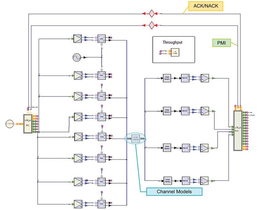
Table 1 shows the evolution of 3GPP’s third generation Universal Mobile
Telecommunication System (UMTS), the original wideband CDMA technology,
starting from its initial release in 1999/2000. There have been a number of
different releases of UMTS, and the addition of High Speed Downlink Packet
Access (HSDPA) in Release 5 ushered in the informally named 3.5G. The
subsequent addition of the Enhanced Dedicated Channel (E-DCH), better known
as High Speed Uplink Packet Access (HSUPA), completed 3.5G. The combination
of HSDPA and HSUPA is now referred to as High Speed Packet Access (HSPA).
LTE arrived with the publication of the Release 8 specifications in 2008 and
LTE-Advanced is being introduced as part of Release 10. The LTE-Advanced
radio access network (RAN) functionality is planned to be functionally frozen
by December 2010 (excluding the ASN.1 definitions) and the overall Release 10
functional freeze is targeted for March 2011.

Table 1. Evolution of UMTS specifications

                Functional
 Release        Freeze            Main Radio Features of the Release
 Rel-99         March 2000        UMTS 3.84 Mcps (W-CDMA FDD & TDD)
 Rel-4          March 2001        1.28 Mcps TDD (aka TD-SCDMA)
 Rel-5          June 2002         HSDPA
 Rel-6          March 2005        HSUPA (E-DCH)
 Rel-7          Dec 2007          HSPA+ (64QAM DL, MIMO, 16QAM UL), LTE & SAE
                                  feasibility study, EDGE Evolution
 Rel-8          Dec 2008          LTE work item – OFDMA air interface,
                                  SAE work item, new IP core network,
                                  3G femtocells, dual carrier HSDPA
 Rel-9          Dec 2009          Multi-standard radio (MSR), dual cell HSUPA
                                  LTE-Advanced feasibility study, SON, LTE femtocells
 Rel-10         March 2011        LTE-Advanced (4G) work item, CoMP study, four
                                  carrier HSDPA

Summary of LTE features
The Long Term Evolution project was initiated in 2004 [2]. The motivation for
LTE included the desire for a reduction in the cost per bit, the addition of lower
cost services with better user experience, the flexible use of new and existing
frequency bands, a simplified and lower cost network with open interfaces,
and a reduction in terminal complexity with an allowance for reasonable power
consumption.

These high level goals led to further expectations for LTE, including reduced
latency for packets, and spectral efficiency improvements above Release 6
high speed packet access (HSPA) of three to four times in the downlink and
two to three times in the uplink. Flexible channel bandwidths—a key feature
of LTE—are specified at 1.4, 3, 5, 10, 15, and 20 MHz in both the uplink and the
downlink. This allows LTE to be flexibly deployed where other systems exist
today, including narrowband systems such as GSM and some systems in the
U.S. based on 1.25 MHz.

                    4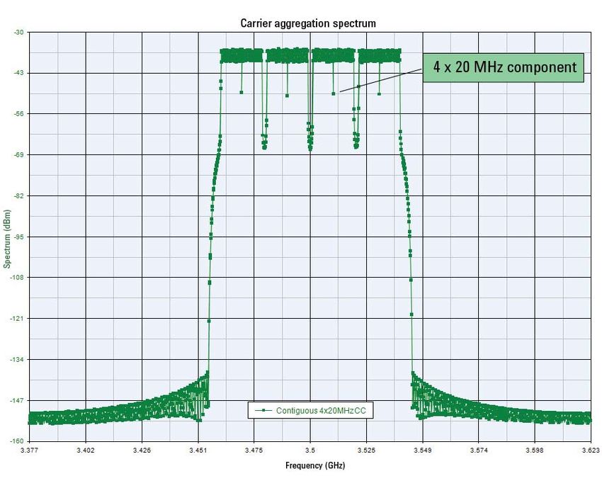
Speed is probably the feature most associated with LTE. Examples of downlink
and uplink peak data rates for a 20 MHz channel bandwidth are shown in Table 2.
Downlink figures are shown for single input single output (SISO) and multiple
input multiple output (MIMO) antenna configurations at a fixed 64QAM modula-
tion depth, whereas the uplink figures are for SISO but at different modulation
depths. These figures represent the physical limitation of the LTE frequency divi-
sion duplex (FDD) radio access mode in ideal radio conditions with allowance
for signaling overheads. Lower rates are specified for specific UE categories,
and performance requirements under non-ideal radio conditions have also been
developed. Figures for LTE’s time division duplex (TDD) radio access mode are
comparable, scaled by the variable uplink and downlink ratios.

Table 2. Peak data rates for LTE

                     Downlink peak data rates (64 QAM)
 Antenna configuration       SISO        2x2 MIMO            4x4 MIMO
 Peak data rate Mbps         100         172.8               326.4
                  Uplink peak data rates (single antenna)
 Modulation                  QPSK        16 QAM              64 QAM
 Peak data rate Mbps         50          57.6                86.4

Unlike previous systems, LTE is designed from the beginning to use MIMO tech-
nology, which results in a more integrated approach to this advanced antenna
technology than does the addition of MIMO to legacy system such as HSPA.

Finally, in terms of mobility, LTE is aimed primarily at low mobility applications
in the 0 to 15 km/h range, where the highest performance will be seen. The
system is capable of working at higher speeds and will be supported with high
performance from 15 to 120 km/h and functional support from 120 to 350 km/h.
Support for speeds of 350 to 500 km/h is under consideration.

                     5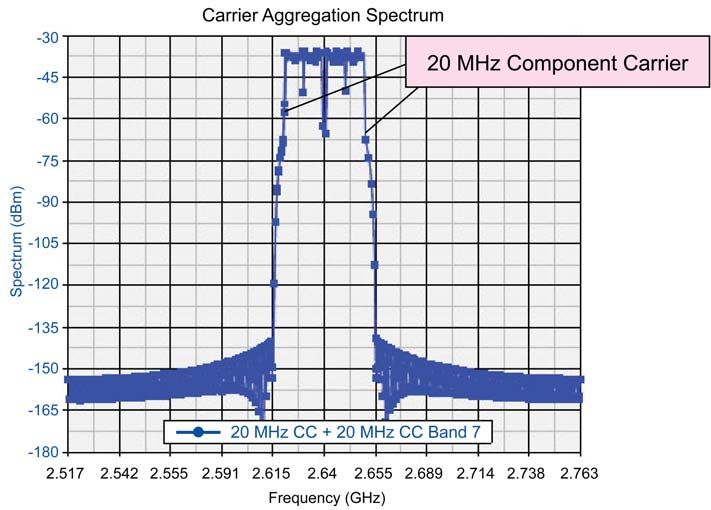
What’s new in LTE-Advanced
In the feasibility study for LTE-Advanced, 3GPP determined that LTE-Advanced
would meet the ITU-R requirements for 4G. The results of the study are pub-
lished in 3GPP Technical Report (TR) 36.912. Further, it was determined that
3GPP Release 8 LTE could meet most of the 4G requirements apart from uplink
spectral efficiency and the peak data rates. These higher requirements are
addressed with the addition of the following LTE-Advanced features:
• Wider bandwidths, enabled by carrier aggregation
• Higher efficiency, enabled by enhanced uplink multiple access and enhanced
  multiple antenna transmission (advanced MIMO techniques)
Other performance enhancements are under consideration for Release 10 and
beyond, even though they are not critical to meeting 4G requirements:
•   Coordinated multipoint transmission and reception (CoMP)
•   Relaying
•   Support for heterogeneous networks
•   LTE self-optimizing network (SON) enhancements
•   Home enhanced-node-B (HeNB) mobility enhancements
•   Fixed wireless customer premises equipment (CPE) RF requirements
These features and their implications for the design and test of LTE-Advanced
systems will be discussed in detail later in this application note.

3GPP documents for LTE-Advanced
3GPP publishes all the documents relating to the development of LTE-Advanced.
These documents are free to the public and can be downloaded from the 3GPP
web site (www.3GPP.org) or at the addresses given below. The versions and
dates shown here are current at the time of this writing.

Study Item RP-080599
Outlines the overall goals of LTE-Advanced
ftp://ftp.3gpp.org/tsg_ran/TSG_RAN/TSGR_41/Docs/RP-080599.zip

Requirements TR 36.913 v9.0.0 (2009-12)
Defines requirements based on the ITU requirements for 4G systems
ftp://ftp.3gpp.org/Specs/html-info/36913.htm

Study Phase Technical Report TR 36.912 v9.3.0 (2010-06)
Summarizes the stage 1 development work
ftp://ftp.3gpp.org/Specs/html-info/36912.htm

Study item final status report RP-100080
ftp://ftp.3gpp.org/tsg_ran/TSG_RAN/TSGR_47/Docs/RP-100080.zip

Physical Layer Aspects TR 36.814 v9.0.0 (2010-03)
Summarizes the stage 2 development for the physical layer
ftp://ftp.3gpp.org/Specs/html-info/36814.htm

Study phase Technical Report on E-UTRA UE Radio Transmission and Reception
TR 36.807
Summarizes study of CA, enhanced multiple antenna transmission and CPE
ftp.3gpp.org/Specs/html-info/36807.htm

Stage 3 technical specifications begin to appear in the Release 10 36-series
documents dated 2010-09.

                   6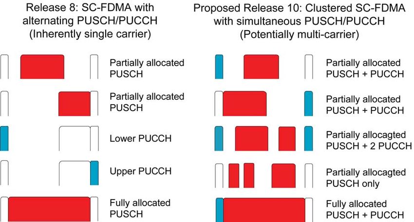
LTE-Advanced timeline
        Work on Release 8 LTE, including test development, is expected to be finished
        in 2010. The Global Certification Forum (GCF) released its scheme for test
        validation in early 2010 and will release a scheme for User Equipment (UE)
        certification by late 2010, when it expects to see the first major wave of LTE
        commercial network rollouts [3]. Deployment is expected to continue over the
        next few years. The deployment timeline for LTE-Advanced will be influenced by
        the success of LTE in the market.

        Figure 2 shows the timeline for the development of IMT-Advanced and
        LTE-Advanced. At the top of the figure is the timeline of the ITU-R, which is
        developing the fourth generation requirements, which are described in more
        detail in the next section. In March 2008, the ITU-R issued an invitation for
        proposals for a new radio interface technology (RIT), with a cutoff date of
        October 2009 for submission of candidate RIT proposals. The cutoff date
        for submitting the technology evaluation report to the ITU was June 2010. In
        October 2010 the ITU Working Party 5D (WP 5D) decided that the first two RITs
        to meet the IMT-Advanced requirements were 3GPP’s LTE-Advanced and IEEE’s
        WirelessMAN-Advanced, which is also known as 802.16m [4]. WP 5D is sched-
        uled to complete development of radio interface specification recommendations
        by February 2011.

        The bottom of Figure 2 shows the work by 3GPP on LTE-Advanced, which is
        occurring in parallel with the development of the ITU requirements. With the
        completion of the documents listed at the bottom of the figure, 3GPP formally
        submitted LTE-Advanced to the ITU as an IMT-Advanced candidate technology.

        2008         2009             2010          2011         2012            2013
                    Proposals

                      Evaluation
ITU-R
                         Consensus

                                    Specification                Early deployment?
            Rel-9 study item Rel-10 study item
3GPP

                                                TR36.912
                                                  -      v 2.2.0
                                                R1-093731, Characteristic template
               ITU - R Submission Sept 2009
                                                R1-093682, Compliance template
                                                R1-093741, Link Budget template

        Figure 2. Timelines for IMT-Advanced (4G) and LTE-Advanced development

                             7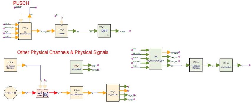
ITU Requirements for IMT-Advanced (4G)
                        The third generation of cellular radio technology was defined by the ITU-R
                        through the International Mobile Telecommunications 2000 project (IMT-2000).
                        The requirements for IMT-2000, defined in 1997, were expressed only in terms of
                        peak user data rates:

                        •   2048 kbps for indoor office
                        •   384 kbps for outdoor to indoor and pedestrian
                        •   144 kbps for vehicular
                        •   9.6 kbps for satellite

                        Of significance is that there was no requirement defined for spectral efficiency
                        in 3G. The situation is quite different for IMT-Advanced.

                        The ITU’s high level requirements for IMT-Advanced include the following [5]:

                        • A high degree of common functionality worldwide while retaining the
                          flexibility to support a wide range of local services and applications in a cost-
                          efficient manner
                        • Compatibility of services within IMT and with fixed networks
                        • Capability for interworking with other radio systems
                        • High quality mobile services
                        • User equipment suitable for worldwide use
                        • User-friendly applications, services, and equipment
                        • Worldwide roaming capability
                        • Enhanced peak data rates to support advanced mobile services and applica-
                          tions (in the downlink, 100 Mbps for high mobility and 1 Gbps for low mobility)

                        For the most part these are general purpose requirements that any good
                        standard would attempt to achieve. The key requirement that sets 4G apart from
                        previous standards is reflected in the last item, which gives the expectations
                        for peak data rates that reach as high 1 Gbps for low mobility applications and
                        100 Mbps for high mobility. This is a huge increase from 3G, which specified a
                        peak rate of 2 Mbps for indoor low mobility applications and 144 kbps vehicular.
                        The peak rates targeted for 4G will have fundamental repercussions on system
                        design.

                        To date, 14 industry groups have registered with the ITU to evaluate whether or
                        not the technology proposals submitted as candidates for 4G meet the require-
                        ments.

                        In addition to the general requirements above there are specific requirements
                        for spectral efficiency summarized later in Table 3.

                                            8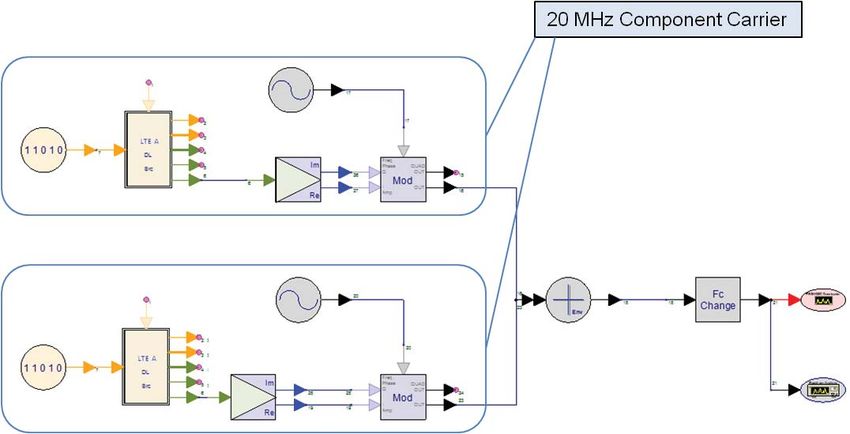
3GPP Requirements for LTE-Advanced
                       The work by 3GPP to define a 4G candidate radio interface technology started
                       in Release 9 with the study phase for LTE-Advanced. The requirements for
                       LTE-Advanced are defined in 3GPP Technical Report (TR) 36.913, “Requirements
                       for Further Advancements for E-UTRA (LTE-Advanced) [6].” These requirements
                       are based on the ITU requirements for 4G and on 3GPP operators’ own require-
                       ments for advancing LTE. Major technical considerations include the following:
                       •   Continual improvement to the LTE radio technology and architecture
                       •   Scenarios and performance requirements for interworking with legacy
                           radio access technologies
                       •   Backward compatibility of LTE-Advanced with LTE. An LTE terminal should
                           be able to work in an LTE-Advanced network and vice versa. Any exceptions
                           will be considered by 3GPP.
                       •   Account taken of recent World Radiocommunication Conference (WRC-07)
                           decisions regarding new IMT spectrum as well as existing frequency bands
                           to ensure that LTE-Advanced geographically accommodates available
                           spectrum for channel allocations above 20 MHz. Also, requirements must
                           recognize those parts of the world in which wideband channels are not
                           available.

                       3GPP cites the fact that IMT-conformant systems will be candidates for any
                       new spectrum bands identified by WRC-07 as one reason to align LTE-Advanced
                       with IMT-Advanced [7]. In addition, it is significant that the ITU has renamed
                       its IMT-2000 spectrum as “IMT” spectrum with the intention that all spectrum
                       previously identified for IMT-2000 (3G) is also applicable for IMT-Advanced (4G).
                       This is significant because it means there is no such thing as 3G spectrum or 4G
                       spectrum; there is just one pool of IMT spectrum. What then drives deployment
                       of specific technologies in specific bands will depend on local circumstances.
                       It could be argued this ITU decision frees up the industry to make appropriate
                       local decisions but it also has the effect of increasing the likely fragmentation of
                       markets. The frequency band choices for early 2G and 3G systems were far sim-
                       pler and focused the industry on one or two key bands (900 MHz for GSM and
                       2.1 GHz for W-CDMA). No comparable focus exists for LTE and LTE-Advanced,
                       with Release 10 having upwards of 30 bands defined from the outset.

                       System performance requirements
                       The system performance requirements for LTE-Advanced will in most cases
                       exceed those of IMT-Advanced. The 1 Gbps peak data rate required by the ITU
                       will be achieved in LTE-Advanced using 4x4 MIMO and transmission bandwidths
                       wider than approximately 70 MHz [8]. In terms of spectral efficiency, today’s LTE
                       (Release 8) satisfies the 4G requirement for the downlink, but not for the uplink.

                       Table 3 compares the spectral efficiency targets for LTE, LTE-Advanced, and
                       IMT-Advanced. Note that the peak rates for LTE-Advanced are substantially
                       higher than the 4G requirements, which highlights a desire to drive up peak
                       performance in 4G LTE, although targets for average performance are closer to
                       ITU requirements. It’s worth noting that peak targets, because they can be met
                       in ideal circumstances, are often easier to demonstrate than average targets.
                       However, TR 36.913 states that targets for average spectral efficiency and for
                       cell-edge user throughput efficiency should be given higher priority than targets
                       for peak spectral efficiency and other features such as VoIP capacity5. Thus the
                       work of LTE-Advanced should be focused on the very real challenges of raising
                       average and cell-edge performance.

                                          9
Table 3. Performance targets for LTE, Advanced-LTE, and IMT-Advanced

                                                               LTE-
                                          LTE (3.9G)      Advanced (4G) IMT-Advanced
          Item            Subcategory     target [9]        target [10] (4G) target [11]
                               Downlink       16.3         30 (up to 8x8        15
       Peak spectral                      (4x4 MIMO)          MIMO)        (4x4 MIMO)
    efficiency (b/s/Hz)         Uplink         4.32        15 (up to 4x4       6.75
                                          (64 QAM SISO)       MIMO)        (2x4 MIMO)
       Downlink cell           2x2 MIMO       1.69              2.4
    spectral efficiency        4.2 MIMO       1.87              2.6            2.6
        (b/s/Hz),
    3 km/h, 500 m ISD          4x4 MIMO       2.67              3.7

      Downlink cell-           2x2 MIMO       0.05             0.07
    edge user spectral         4x2 MIMO       0.06             0.09           0.075
     efficiency (b/s/
     Hz) 5 percentile,
     10 users, 500 m           4x4 MIMO       0.08             0.12
            ISD
*Note: ISD = Inter-site distance

Spectrum flexibility
In addition to the bands currently defined for LTE Release 8, TR 36.913 identifies
the following new bands:
•    450–470 MHz band
•    698–862 MHz band
•    790–862 MHz band
•    2.3–2.4 GHz band
•    3.4–4.2 GHz band
•    4.4–4.99 GHz band

Some of these bands are now formally included in the 3GPP Release 9 and
Release 10 specifications. Note that frequency bands are considered release-
independent features, which means that it is acceptable to deploy an earlier
release product in a band not defined until a later release.

LTE-Advanced is designed to operate in spectrum allocations of different sizes,
including allocations wider than the 20 MHz in Release 8, in order to achieve
higher performance and target data rates. Although it is desirable to have
bandwidths greater than 20 MHz deployed in adjacent spectrum, the limited
availability of spectrum means that aggregation from different bands is neces-
sary to meet the higher bandwidth requirements. This option has been allowed
for in the IMT-Advanced specifications.

                          10
LTE-Advanced and Other Release 10 Solution Proposals
Proposed solutions for achieving LTE-Advanced performance targets for the
radio interface are defined in 3GPP TR 36.814, “Further Advancements for
E-UTRA Physical Layer Aspects.” [12] A comprehensive summary of the overall
LTE-Advanced proposals including radio, network, and system performance
can be found in the 3GPP submissions to the first IMT-Advanced evaluation
workshop. [13] The remainder of this application note will focus on the radio
interface of LTE-Advanced and other Release 10 features.
The following are current solution proposals for the LTE-Advanced radio interface.
LTE-Advanced key technologies
• Carrier aggregation
• Enhanced uplink multiple access
• Enhanced multiple antenna transmission
Within Release 10 there is other ongoing work that is complementary to LTE-
Advanced but not considered essential for meeting the ITU requirements.
Release 10 and beyond: Technologies under consideration
• Coordinated multipoint transmission and reception (CoMP)
• Relaying
• Support for heterogeneous networks
• LTE self-optimizing networks (SON)
• HNB and HeNB mobility enhancements
• CPE RF requirements
We’ll examine each of these categories from the physical layer perspective,
along with some of the associated design and test challenges.
Prior to the elaboration of the Release 10 UE radio specifications in 36.101,
Technical Report (TR) 36.807 [14] is being drafted. This will cover the following
Release 10 features:
• Carrier Aggregation (CA)
• Enhanced DL multiple antenna (DLMA) transmission
• UL multiple antenna (ULMA) transmission
• Fixed wireless CPE RF requirements
Like most technical reports, this document contains useful background informa-
tion on how the requirements were developed which will not necessarily be
evident in the final technical specifications.
11Release 10 new UE categories
The existing UE categories 1-5 for Release 8 and Release 9 are shown in Table 4.
In order to accommodate LTE-Advanced capabilities, three new UE categories
Table 4. Release 10 UE categories 6-8 have been defined. [15]
Downlink Uplink
Max. data Max. # Max. # Max. #
rate DL-SCH DL-SCH Total soft Max. #. Max.# UL-SCH
UE (DL/UL) TB bits/ bits/TB/ channel spatial UL-SCH TB bits/TB/ Support for
category (Mbps) TTI TTI bits layers bits/TTI TTI 64 QAM
Category 1 10/5 10296 10296 250368 1 5160 5160 No
Category 2 50/25 51024 51024 1237248 2 25456 25456 No
Category 3 100/50 102048 75376 1237248 2 51024 51024 No
Category 4 150/50 150752 75376 1827072 2 51024 51024 No
Category 5 300/75 299552 149776 3667200 4 75376 75376 Yes
Category 6 300/50 [299552] [TBD] [3667200] * [51024] [TBD] No
Category 7 300/150 [299552] [TBD] [TBD] * [150752/102048 [TBD] Yes/No
(Up to RAN4)] (Up to RAN4)
Category 8 1200/600 [1200000] [TBD] [TBD] * [600000] [TBD] Yes
*See Tables 5 and 6
Note that category 8 exceeds the requirements of IMT-Advanced by a considerable
margin.
Given the many possible combinations of layers and carrier aggregation, many con-
figurations could be used to meet the data rates in Table 4. Tables 5 and 6 define
the most probable cases for which performance requirements will be developed.
Table 5. Downlink configurations Table 6. Uplink configurations
DL CA capability DL layers UL CA capability UL layers
#CCs/BW(MHz) max # layers #CCs/BW(MHz) max # layers
UE category [provisional] [provisional] UE category [provisional] [provisional]
1/20 MHz 4 1/20 MHZ 1
2/10+10 MHz 4 Category 6 2/10+10 MHz 1
Category 6 2/20+20 MHz 2 1/10 MHz 2
2/10+20 MHz 4 (10 MHz) 2/20+20 MHZ 1
2 (20 MHz) 1/20 MHz 2
Category 7
1/20 MHz 4 2/10+20 MHz 2 (10 MHz)
2/10+10 MHz 4 1 (20 MHz)
Category 7 2/20+20 MHz 2 Category 8 [2/20+20 MHz] [4]
2/10+20 MHz 4 (10 MHz)
2 (20 MHz)
Category 8 [2/20+20 MHz] [8]
12LTE-Advanced key technologies
Carrier aggregation
Achieving the 4G target downlink peak data rate of 1 Gbps will require wider
channel bandwidths than are currently specified in LTE Release 8. At the
moment, LTE supports channel bandwidths up to 20 MHz, and it is unlikely
that spectral efficiency can be improved much beyond current LTE performance
targets. Therefore the only way to achieve significantly higher data rates is to
increase the channel bandwidth. IMT-Advanced sets the upper limit at 100 MHz,
with 40 MHz the expectation for minimum performance.
Because most spectrum is occupied and 100 MHz of contiguous spectrum is
not available to most operators, the ITU has allowed the creation of wider band-
widths through the aggregation of contiguous and non-contiguous component
carriers. Thus spectrum from one band can be added to spectrum from another
band in a UE that supports multiple transceivers. Figure 3 shows an example of
contiguous aggregation in which two 20 MHz channels are located side by side.
In this case the aggregated bandwidth covers the 40 MHz minimum requirement
and could be supported with a single transceiver. However, if the channels in
this example were non-contiguous—that is, not adjacent, or located in different
frequency bands—then multiple transceivers in the UE would be required.
Figure 3. Contiguous aggregation of two uplink component carriers
The term component carrier used in this context refers to any of the bandwidths
defined in Release 8/9 LTE. To meet ITU 4G requirements, LTE-Advanced will
support three component carrier aggregation scenarios: intra-band contiguous,
intra-band non-contiguous, and inter-band non-contiguous aggregation. The
spacing between center frequencies of contiguously aggregated component car-
riers will be a multiple of 300 kHz to be compatible with the 100 kHz frequency
raster of Release 8/9 and at the same time preserve orthogonality of the
subcarriers, which have 15 kHz spacing. Depending on the aggregation scenario,
the n x 300 kHz spacing can be facilitated by inserting a low number of unused
subcarriers between contiguous component carriers. In the case of contiguous
aggregation, more use of the gap between component carriers could be made,
but this would require defining new, slightly wider component carriers.
An LTE-Advanced UE with capabilities for receive and/or transmit carrier
aggregation will be able to simultaneously receive and/or transmit on multiple
component carriers. A Release 8 or 9 UE, however, can receive and transmit on
a single component carrier only. Component carriers must be compatible with
LTE Release 8 and 9.
13In Release 10, the maximum size of a single component carrier is limited to 110
resource blocks, although for reasons of simplicity and backwards compatibility
it is unlikely that anything beyond the current 100 RB will be specified. Up to 5
component carriers may be aggregated. An LTE-Advanced UE cannot be config-
ured with more uplink component carriers than downlink component carriers,
and in typical TDD deployments the number of uplink and downlink component
carriers, as well as the bandwidth of each, must be the same.
For mapping at the physical layer (PHY) to medium access control (MAC) layer
interface, there will be one transport block (in the absence of spatial multiplex-
ing) and one hybrid-ARQ entity for each scheduled component carrier. (Hybrid
ARQ is the control mechanism for retransmission.) Each transport block will be
mapped to a single component carrier only. A UE may be scheduled over mul-
tiple component carriers simultaneously. The details of how the control signaling
will be handled across the multiple carriers are still being developed.
Aggregation techniques are not new to 4G; aggregation is also used in HSPA
and 1xEV-DO Release B. However, the 4G proposal to extend aggregation to 100
MHz in multiple bands raises considerable technical challenges owing to the
cost and complexity that will be added to the UE. Moreover, operators will have
to deal with the challenge of deciding what bands to pick for aggregation and it
may be some time before consensus is reached allowing sufficient scale to drive
the vendor community. 3GPP initially identified 12 likely deployment scenarios
for study with the intention of identifying requirements for spurious emissions,
maximum power, and other factors associated with combining different radio
frequencies in a single device. However, because of the number of the scenarios
and limited time, the study for Release 10 LTE-Advanced was initially limited to
two scenarios, one intra-band TDD example and one inter-band FDD example.
In June 2010 a third scenario was added for bands 3 and 7, as shown in Table 7.
This scenario is an important combination for Europe, where re-farming of the
underused 1800 MHz band currently allocated to GSM is a significant possibility.
Table 7. 3GPP Release 10 carrier aggregation (CA) scenarios for study [16]
Uplink (UL) band Downlink (DL) band
E-UTRA UE transmit/BS receive UE receive/BS transmit Duplex
operating Channel Channel mode
Band Band FUL_low (MHz) – FUL_high (MHz) BW MHz FDL_low (MHz) – FDL_high (MHz) BW MHz
CA_40 40 2300 – 2400 [TBD] 2300 – 2400 [TBD] TDD
1 1920 – 1980 [TBD] 2110 – 2170 [TBD]
CA_1-5 FDD
5 824 – 849 [TBD] 869 – 894 [TBD]
3 1710 – 1788 20 1805 – 1880 20
CA_3-7 FDD
7 2500 – 2570 20 2620 – 2690 20
The physical layer definition for CA is considered 80% complete and although
the CA concept is simple, the details of the physical layer changes to support the
signaling are complex and involve changes to the PCFICH, PHICH, PDCCH, PUCCH,
UL power control, PUSCH resource allocation, and the UCI on the PUSCH. The
radio performance aspects are only at 30% completion. This is significant, as Table
7 just begins to describe the possible scope of CA. To get some idea of the number
of combinations requested by operators, refer to Annex A of TR 36.807. Every com-
bination introduced into the specifications has to be assessed for aspects such as
required guard bands, spurious emissions, power back off, and so forth.
14One of the new challenges that CA introduces to the radio specifications is
the concept of variable TX/RX frequency separation. This attribute impacts
specifications for reference sensitivity and receiver blocking, among others. In
Release 8 and Release 9, the TX and RX separation for each of the 19 defined
FDD bands is fixed. The introduction of CA changes that, since asymmetric
uplink and downlink allocations will be commonplace. The asymmetry is driven
by three scenarios; different numbers of CCs in the uplink and downlink, differ-
ent bandwidths of CC in the uplink and downlink, and finally a combination of
different bandwidths and numbers of CCs. How to limit the allowed allocations
in order to minimize the number of test scenarios is still under study.
Enhanced uplink multiple access
Today’s LTE uplink is based on SC-FDMA, a powerful technology that combines
many of the flexible aspects of OFDM with the low peak to average power ratio
(PAPR) of a single carrier system. However, SC-FDMA requires carrier allocation
across a contiguous block of spectrum and this prevents some of the scheduling
flexibility inherent in pure OFDM.
LTE-Advanced enhances the uplink multiple access scheme by adopting clustered
SC-FDMA, also known as discrete Fourier transform spread OFDM (DFT-S-OFDM).
This scheme is similar to SC-FDMA but has the advantage that it allows non-
contiguous (clustered) groups of subcarriers to be allocated for transmission
by a single UE, thus enabling uplink frequency-selective scheduling and better
link performance. Clustered SC-FDMA was chosen in preference to pure OFDM
to avoid a significant increase in PAPR. It will help satisfy the requirement for
increased uplink spectral efficiency while maintaining backward-compatibility
with LTE.
Figure 4 shows a block diagram for the enhanced uplink multiple access (clus-
tered SC-FDMA) process. There is only one transport block and one hybrid ARQ
entity per scheduled component carrier. Each transport block is mapped to a
single component carrier, and a UE may be scheduled over multiple component
carriers simultaneously using carrier aggregation, as described in the previous
section.
0
0
0
0
0
0
0
0
0
MAC Mapping
CP
Coding Modulation DFT IFFT
PDU Insertion
0
0
0
0
0
0
0
Figure 4. Enhanced uplink multiple access block diagram
15Examples of different Release 8 and Release 10 uplink configurations are given
in Figure 5. The key point is that all Release 8 configurations are single carrier,
which means that the PAPR is no greater than the underlying QPSK or 16QAM
modulation format, whereas in Release 10 it is possible to transmit more than
one carrier, which makes the PAPR higher than the Release 8 cases. Note that
the multiple carriers referred to here as part of clustered SC-FDMA and simulta-
neous PUCCH/PUSCH are contained within one component carrier and should
not be confused with the multiple component carriers of CA.
Release 8: SC-FDMA with Proposed Release 10: Clustered SC-FDMA
alternating PUSCH/PUCCH with simultaneous PUSCH/PUCCH
(Inherently single carrier) (Potentially multi-carrier)
Partially allocated Partially allocated
PUSCH PUSCH + PUCCH
Partially allocated Partially allocated
PUSCH PUSCH + PUCCH
Partially allocated
Lower PUCCH PUSCH + 2 PUCCH
Upper PUCCH Partially allocated
PUSCH only
Fully allocated Fully allocated
PUSCH PUSCH + PUCCH
Figure 5. Comparison of Release 8 and proposed Release 10 uplink configurations
The initial specifications are likely to limit the number of SC-FDMA clusters to
two, which will provide some improved spectral efficiency over single cluster
when transmitting through a frequency-selective channel with more than one
distinct peak.
Enhanced multiple antenna transmission
Figure 6 shows the Release-8 LTE limits for antenna ports and spatial mul-
tiplexing layers. The downlink supports a maximum of four spatial layers of
transmission (4x4, assuming four UE receivers) and the uplink a maximum of
one per UE (1x2, assuming an eNB diversity receiver). In Release 8, multiple
antenna transmission is not supported in order to simplify the baseline UE,
although multiple user spatial multiplexing (MU-MIMO) is supported. In the case
of MU-MIMO, two UEs transmit on the same frequency and time, and the eNB
has to differentiate between them based on their spatial properties. With this
multi-user approach to spatial multiplexing, gains in uplink capacity are available
but single user peak data rates are not improved.
Max 4 layers/antennas
Max 1 layer/antenna
Figure 6. Release 8 LTE maximum number of antenna ports and spatial layers
16To improve single user peak data rates and to meet the ITU-R requirement for
spectrum efficiency, LTE-Advanced specifies up to eight layers in the downlink
which, with the requisite eight receivers in the UE, allows the possibility in
the downlink of 8x8 spatial multiplexing. The UE will be specified to support
up to four transmitters allowing the possibility of up to 4x4 transmission in the
uplink when combined with four eNB receivers. See Figure 7.
Max 8 layers/antennas
Max 4 layers/antennas
Figure 7. LTE-Advanced maximum number of antenna ports and spatial layers
The work to define the enhanced downlink is about 80% complete. There will
be changes to the UE-specific demodulation reference signal (DMRS) patterns
to support up to eight antennas. Channel state information reference signals
(CSI-RS) and associated modifications to UE feedback in the CSI codebook
design will be introduced. There also will be equivalent changes for downlink
control signaling.
The specification for DMRS for Ranks 1 to 4 is given in Figure 8. DMRS
support for Ranks 5 to 8 is not defined for Release 10 but is not precluded
in future releases. Release 10 emphasizes dual-layer spatial multiplexing
augmented by four-antenna beamsteering rather than a pure 8-layer spatial
multiplexing approach, which would offer higher peak rates but require eight
receive antennas in the UE.
R7 R7 R7 R7 R 8 R8 R 8 R8
R9 R9 R9 R9 R10 R10 R10 R10
All other downlink subframes
R7 R7 R7 R7 R 8 R8 R 8 R8
R9 R9 R9 R9 R10 R10 R10 R10
R7 R7 R7 R7 R8 R8 R 8 R8
R9 R9 R9 R9 R10 R10 R10 R10
l =0 l =6 l =0 l =6 l =0 l =6 l =0 l =6 l =0 l =6 l =0 l =6 l =0 l =6 l =0 l =6
even-numbered slots odd-numbered slots even-numbered slots odd-numbered slots even-numbered slots odd-numbered slots even-numbered slots odd-numbered slots
Antenna port 7 Antenna port 8 Antenna port 9 Antenna port 10
Figure 8. Mapping of UE-specific reference signals; antenna ports 7, 8, 9, and 10 (normal cycle prefix) [17]
17The CSI-RS are introduced in the downlink to enable UE-specific weights to be
applied to the RS for UE channel measurement purposes according to the CSI
feedback. In this way the behavior of the UE-specific RS will track that of the
precoded data (PDSCH), which is already optimized for each UE. The design of
the CSI-RS offers other advantages over the legacy CRS in that higher reuse factors
are available, which makes the introduction of inter-cell interference cancellation
(ICIC) more practical. The proposed mappings of the CSI-RS for two, four, and
eight antenna ports is given in Figure 9.
R15 R15 R16 R16
R17 R17 R18 R18
l =0 l =6 l =0 l =6 l =0 l =6 l =0 l =6 l =0 l =6 l =0 l =6 l =0 l =6 l =0 l =6
R19 R19 R 20 R 20
R 21 R 21 R 22 R 22
l =0 l =6 l =0 l =6 l =0 l =6 l =0 l =6 l =0 l =6 l =0 l =6 l =0 l =6 l =0 l =6
even-numbered slots odd-numbered slots even-numbered slots odd-numbered slots even-numbered slots odd-numbered slots even-numbered slots odd-numbered slots
Figure 9. Mapping of CSI reference signals (CSI configuration 0, normal cyclic prefix) [18]
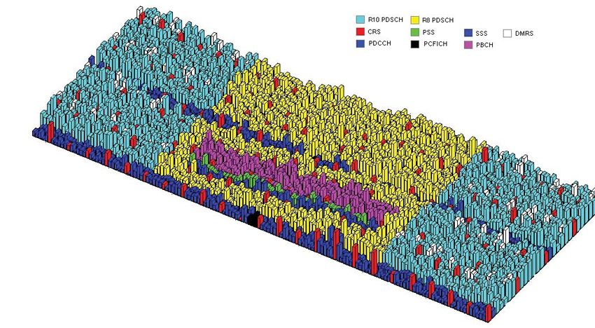
Figure 10 illustrates the resource block (RB) allocation for a 10 MHz FDD signal
transmitted over an EPA channel as seen at the antenna of a single input UE.
This particular signaling configuration was created using Agilent SystemVue
along with a “beta” version of its LTE-Advanced Release 10 library.
Figure 10. Example of resource block allocation in LTE-Advanced
The allocation shown in Figure10 is extracted from the center 12 RBs in the
first two subframes of a 10 MHz FDD downlink signal. Normal cyclic prefix is
employed. The first two symbols of each subframe are reserved for the PDCCH.
The center of the channel has been used for Release 8 PDSCH and the outer
RBs for Release 10 PDSCH. Included in the allocation are cell-specific RS along
with Release 10 DMRS.
18The principles for a new codebook for the 8Tx case have been agreed to, but for
the 2Tx and 4Tx cases, the Release 8 codebook will be reused as it is considered
good enough. However, several proposals are being considered to improve CQI/
PMI/RI accuracy for both MU-MIMO and SU-MIMO:
• Aperiodic PUSCH CQI mode 3-2 (sub-band CQI + sub-band PMI)
• Extension of Release 8 periodic PUCCH CQI mode 2-1 with sub-band PMI
• Potential enhancement on CQI for MU
• Potential enhancement on interference measurement for CQI
• UE procedure to derive PMI targeting for both MU-MIMO and SU-MIMO
Extensions of some of the Release 8 aperiodic PUSCH CQI feedback modes
(1-2, 2-2, and 3-1) is proposed along with extensions of the periodic PUCCH
modes 1-1 and 2-1.
Various modifications to the downlink control signaling have been agreed to
including the following:
• Support of 2 orthogonal DMRS ports and 2 scrambling sequences for
MU-MIMO operation
• No additional signaling to be added for the MU-MIMO case in which one RB
is scheduled to more than one UE
• Additions to support the new 8Tx SU-MIMO mode dynamic switching
between SU-MIMO and MU-MIMO
Equivalent work is ongoing to define multiple antenna transmission for the
uplink. Note that in Release 8 and Release 9, only single antenna uplink
transmission was defined, so the work in release 10 is not an enhancement
as is the case for multiple antenna downlink transmission, which was defined
for four antennas in Release 8 and enhanced to 8 antennas in Release 10. A
major issue is how uplink control information (UCI) will be multiplexed between
two or more PUSCH. This is also an issue for carrier aggregation. Essential
agreements have been reached on resource sizes for HARQ, RI, CQI, and PMI.
Agreement has been reached on mapping of the PHICH on the downlink for
uplink SU-MIMO, and on the cyclic shift and orthogonal cover code (OCC) defi-
nitions for the uplink DMRS. Enhancements to the sounding reference symbols
(SRS) have been proposed.
The physical layer definition for multiple antenna transmission is well advanced,
although the radio performance aspects for the UE and eNB are still in the early
stages of discussion with completion not expected until June 2011.
19Release 10 and beyond: Technologies under consideration
Coordinated multipoint transmission and reception
Coordinated multipoint (CoMP) is an advanced variant of MIMO being studied
as a means of improving performance for high data rates, cell-edge throughput,
and system throughput in high load and low load scenarios.
Figure 11 compares traditional MIMO downlink spatial multiplexing with
coordinated multipoint. The most obvious different between the two systems is
that with coordinated multipoint, the transmitters do not have to be physically
co-located, although they are linked by some type of high speed data connec-
tion and can share payload data.
Traditional MIMO: co-located transmission Coordinated multipoint
Tx0 Rx0 Tx0 Rx0
Tx1 Rx1 Tx1 Rx1
eNB UE eNB 2 UE
Figure 11. Comparison of traditional downlink MIMO and coordinated multipoint
In the downlink, coordinated multipoint enables coordinated scheduling and
beamforming from two or more physically separated locations. These features
do not make full use of CoMP’s potential, because the data required to transmit
to the mobile needs to be present at only one of the serving cells. However, if
coherent combining, also known as cooperative or network MIMO, is used, then
more advanced transmission is possible.
The CoMP approach to MIMO requires high speed, symbol-level data com-
munication between all the transmitting entities, as indicated on the right hand
side of Figure 11 by a line between eNB1 and eNB2. Most likely the physical
link carrying the LTE X2 interface, a mesh-based interface between the base
stations, will be used for sharing the baseband data.
The coherent combining used in CoMP is somewhat like soft combining or
soft handover, a technique that is widely known in CDMA systems in which
the same signal is transmitted from different cells. With coherent combining,
however, the data streams that are being transmitted from the base stations are
not the same. These different data streams are precoded in such a way as to
maximize the probability that the UE can decode the different data streams. In
the uplink, the use of coordination between the base stations is less advanced,
simply because when two or more UEs are transmitting from different places,
there is no realistic mechanism for sharing the data between UEs for the pur-
poses of precoding. Thus the uplink is restricted to using the simpler technique
of coordinated scheduling. On the other hand, there is considerable opportunity
at the eNB receivers to share the received data prior to demodulation to enable
more advanced demodulation to be performed. The downside is the conse-
quence that for a 10 MHz signal, the backhaul could be as much as 5 Gbps of
low latency connections between the participating eNBs.
20Simulations of coordinated multipoint have shown that when the system is
not fully loaded, the CoMP process can provide substantial performance gains.
However, as the load on the system increases, these gains begin to disappear.
3GPP’s recent simulation data showed initial performance improvement to be
in the 5% to 15% range. This was not considered sufficient to keep coordinated
multipoint as a proposal in Release 10, given the timeline for finalizing the
specification. Also, recent results from the EASY-C testbed showed limited per-
formance gains in lightly loaded networks with minimal or no interference. [19]
Coordinated multipoint will be studied further for 3GPP Release 11. It remains
unclear what eNB testing of CoMP might entail as it is very much a system-
level performance gain and is difficult to emulate.
Relaying
Another method of improving coverage in difficult conditions is the use of relay-
ing. The main use cases for relays are to improve urban or indoor throughput, to
add dead zone coverage, or to extend coverage in rural areas.
The concept of relaying is not new but the level of sophistication continues to
grow. Figure 12 shows a typical scenario. A relay node (RN) is connected wire-
lessly to the radio access network via a donor cell. In the proposals for Release
10, the RN will connect to the donor cell’s eNB (DeNB) in one of two ways:
• In-band (in-channel), in which case the DeNB-to-RN link shares the same
carrier frequency with RN-to-UE links.
• Out-band, in which case the DeNB-to-RN link does not operate in the same
carrier frequency as RN-to-UE links.
The most basic and legacy relay method is the use of a radio repeater, which
receives, amplifies and then retransmits the downlink and uplink signals to
overcome areas of poor coverage. In the figure, the repeater could be located at
the cell edge or in some other area of poor coverage. Radio repeaters are rela-
tively simple devices operating purely at the RF level. Typically they receive and
retransmit an entire frequency band, so they must be sited carefully. In general,
repeaters can improve coverage but do not substantially increase capacity.
DeNB
Over the air
backhaul eNB
RN
Cell edge
RN
RN
Multi-hop relaying
Area of poor coverage with
no cabled backhaul
Figure 12. In-channel relay and backhaul
21More advanced relays at layer 2 can decode transmissions before retransmitting
them. Traffic can then be forwarded selectively to and from the UE local to the
RN, thus minimizing the interference created by legacy relays that forward all
traffic. Depending on the level at which the protocol stack is terminated in the
RN, such types of relay may require the development of relay-specific standards.
This can be largely avoided by extending the protocol stack of the RN up to
Layer 3 to create a wireless router that operates in the same way that a normal
eNB operates, using standard air interface protocols and performing its own
resource allocation and scheduling.
The concept of the relay station can be applied in low density deployments
where a lack of suitable backhaul would otherwise preclude use of a cellular
network. The use of in-band or in-channel backhaul can be optimized using
narrow, point-to-point connections to avoid creating unnecessary interference in
the rest of the network. Multi-hop relaying is also possible, as Figure 12 shows.
In this case a signal is sent from the DeNB to the first RN and then on to the
next RN and finally down to the UE. The uplink signal coming back from the UE
gets transmitted up through the RNs and back to the DeNB. This technique is
possible to do in-channel in an OFDMA system because the channel can be split
into UE and backhaul traffic. The link budget between the DeNB and the RN can
be engineered to be good enough to allow the use of some of the subframes
for backhaul of the relay traffic. These subframes are the ones which otherwise
could have been allocated for use with multimedia broadcast in a single fre-
quency network (MBSFN).
In Release 10 progress is being made on the RAN aspects of relaying but it is
likely that the network security aspects will be delayed until Release 11. This
delay may not affect RAN standardization but may impact deployment.
Support for heterogeneous networks
Release 10 intends to address the support needs of heterogeneous networks
that combine low power nodes (such as picocells, femtocells, repeaters, and
RNs) within a macrocell. Deployment scenarios under evaluation are detailed in
TR 36.814 Annex A. [20]
As the network becomes more complex, the subject of radio resource manage-
ment is growing in importance. Work is ongoing to develop more advanced
methods of radio resource management including new self-optimizing network
(SON) features. The Release 10 specifications also continue to develop the use
of femtocells and home base stations (HeNBs) introduced in Release 9 as a
means of improving network efficiencies and reducing infrastructure costs.
22LTE self optimizing network enhancements
Today’s cellular systems are very much centrally planned, and the addition
of new nodes to the network involves expensive and time-consuming work,
site visits for optimization, and other deployment challenges. Some limited
SON capability was introduced in Release 8 and is being further elaborated in
Release 9 and Release 10.
The intent of SON is to substantially reduce the effort required to introduce new
nodes and manage the network. There are implications for radio planning as
well as for the operations and maintenance (O&M) interface to the base station.
The main aspects of SON can be summarized as follows:
• Self configuration–The one-time process of automating a specific event, such
as the introduction of a new femtocell, by making use of the O&M interface
and the network management module
• Self optimization–The continuous process of using environmental data, such
as UE and base station measurements, to optimize the current network set-
tings within the constraints set by the configuration process
• Self healing–The process of recovering from an exceptional event caused by
unusual circumstances, such as dramatically changing interference condi-
tions or the detection of a ping pong situation in which a UE continuously
switches between macro and femto cells.
HeNB mobility enhancements
Another category of network enhancement that will figure prominently in
Release 10 is the femtocell or home eNode B (HeNB).
3GPP work on femtocell inclusion in UMTS was ongoing during Release 8 and
was extended in Release 9 to LTE with the HeNB. In Release 9 only inbound
mobility (macro to HeNB) was fully specified. Further enhancements to enable
HeNB to HeNB mobility will be added in Release 10. Currently three different
proposals for enabling HeNB to HeNB mobility are being studied and a decision
is expected in Dec 2010. This capability is very important for enterprise deploy-
ments. Although the femtocell concept is not unique to LTE or LTE-Advanced,
an opportunity exists for LTE to incorporate this technology from the start rather
than retrospectively designing it into legacy systems such as UMTS and GSM.
Figure 13 shows the topology of a femtocell deployment.
Mobile
Operator
Network
Internet
HeNB
Local
UE
HeNB
B
Local
eN
to H er
UE
N B v
He ando
H
Figure 13. Femtocell deployment in a heterogeneous
23From a radio deployment perspective the femtocell operates over a small area
within a larger cell. The radio channel could be a channel shared with a larger
cell (known as co-channel deployment) or it could be a dedicated channel. The
femtocell concept is fundamentally different from relaying since the femtocell
connection back into the core network is provided locally by an existing DSL or
cable internet connection rather than over the air back to the macrocell. Most
femtocell deployments will be indoors, which helps provide isolation between
the femtocell and macrocell. Also depicted in Figure 13 is a femtocell outside
the macrocell coverage area. This shows how femtocells might be used to
provide local cellular coverage in rural areas where DSL service exists but not
that of the preferred operator.
Although the term “femtocell” suggests that the major difference from existing
systems is one of coverage area, the defining attributes of femtocells are far
more numerous than coverage area alone. They include such considerations as
infrastructure cost and financing; method of backhaul; network planning, deploy-
ment, quality of service, and control; mobility and data throughput performance.
The two main deployment scenarios for femtocells are in the following locations:
• In rural areas with poor or no (indoor) coverage, probably using co-channel
deployment
• In dense areas to provide high data rates and capacity
In both cases operators must decide whether the femtocell will be deployed for
closed subscriber group (CSG) UE or for open access. This and other practical
considerations such as pricing can be considered commercial issues, although
in the co-channel CSG case, the probability that areas of dense femtocell
deployment will block macrocells becomes an issue.
The potential gains from femtocells are substantial, but they present many chal-
lenges. Solutions are needed for many of the following, some of which are being
addressed in Release 10:
• Cognitive methods to reduce interference to the macro network
• Radio resource management requirements
• Methods of addressing security concerns associated with users building their
own cellular networks
• Verification of geographic location and roaming aspects
• Business models for open- versus closed-access operation
• Support of more than one network per femtocell
• Ownership of the backhaul and the issue of net neutrality
• Optimized and balanced interworking between macrocells and femtocells to
minimize unnecessary handovers
• Methods of resolving bottlenecks on fixed broadband backhaul connection,
especially on the uplink for services requiring symmetric bandwidths, prioriti-
zation, and congestion management
• QoS control for real-time services (such as voice) and applications requiring
guaranteed bit rates
• Access control providing closed subscriber group local and roaming access
• Capability for self-configuration, self-organization, self-optimization, and self-
healing (including fault management and failure recovery)
• Security, backhaul protection, device and user authentication
24You can also read