NTL10X OEM-MODULES FAMILY FIRMWARE UPDATE - Reference Manual 2020 - NTLab
←
→
Page content transcription
If your browser does not render page correctly, please read the page content below
NTL10X OEM-MODULES FAMILY
    FIRMWARE UPDATE

     Reference Manual

           2020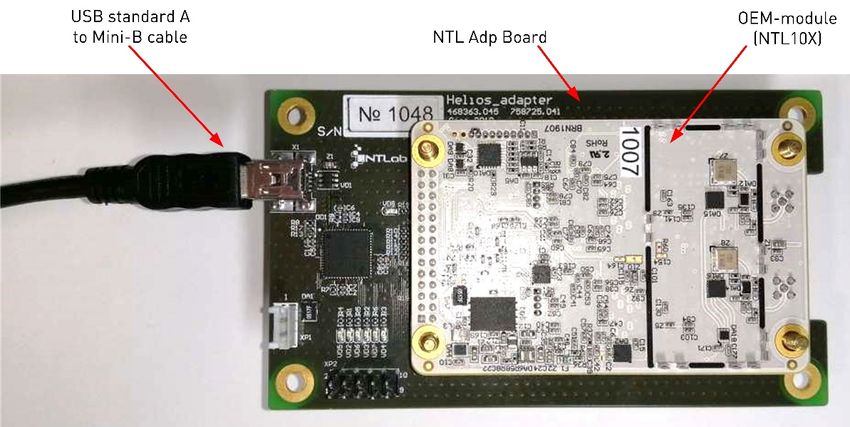
2

TABLE OF CONTENTS

1 GENERAL INFORMATION .............................................................................................................3
2 PPU FIRMWARE UPDATE.............................................................................................................4
3 JTAG PIN DEFINITION ............................................................................................................... 13
CONTACT ........................................................................................................................................ 14
3

         1 GENERAL INFORMATION

         NTL10X navigation receivers have one or two Primary Processing Units (PPU) - see relevant datasheet
on OEM-module - and STM32H7-based RTK coprocessor. Each of these modules requires personal firmware.
Thus, to perform full firmware update, you need three (or two) firmware files.
         PPU interface includes set of commands for firmware flash memory access. Being a part of an
embedded system OEM-module should be reprogrammed by host controller. See «GNSS-DCP-BUILD-
6 - 62 - 00» document for commands description and «GNSS-PPU-SETUP-GUIDE-6-62-00» document for
PPU description. To simplify this procedure OEM board should be connected to PC, then NTL Browser
application should be used to reprogram the module. Special NTL Eva Board (interface adapter) or NTL Adp
Board can be used to connect OEM receiver to PC. Step by step guidance will be stated in the next section.
         The PPUs flash memory is capable of storing two firmware files - backup and basic firmware. The
backup firmware version is programmed by the manufacturer only. Basic firmware can be updated by the user
in a secure manner. In the case of a failure in the basic firmware updating process, the backup version will be
used to load from and the device will remain functional. Special boot marker determines which firmware file
to use upon start up. Boot marker setting is available via NTL Browser application as well, so both firmware
versions can be used. If any receiver settings were saved in flash memory, they would be erased after firmware
update. The receiver will start up with the default settings predefined by new firmware.
         STM32H7 1 MCU reprogramming is available via JTAG interface only and requires some special
hardware and software tools. See Section 3 for pin assignment of XP4 (JTAG) connector. ST-LINK/V2 (or any
other compatible) debugging/programming tool should be used as well as appropriate drivers and software.
         Before working with the OEM-module, refer to its actual datasheet to get information about its structure
and basic features.

1
    Included in the NTL101, NTL104, NTL105 and NTL106 OEM-modules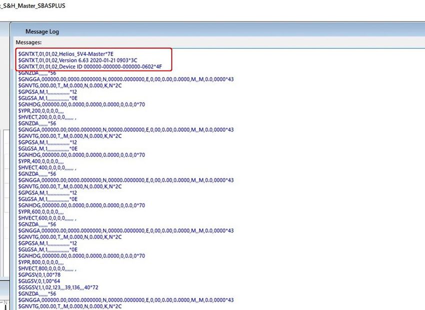
4

         2 PPU FIRMWARE UPDATE

         You are provided with the receiver having the latest version of firmware already installed. When more
actual version of the firmware becomes available, you can use the NTL Browser to update the firmware on
your receiver.
         NTL Browser is a software tool designed to communicate with NTL10X through NTL Adp Board. NTL
Browser provided as a zip file. It is available on NTLab company FTP server. Link (password and login) may be
provided on request.
         To upgrade the firmware:
         1. Install NTL Browser on computer.
         2. Install CP210x drivers on computer. Utility software downloadable from:
         https://www.silabs.com/products/development-tools/software/usb-to-uart-bridge-vcp-drivers
         3. Connect NTL10X to the NTL Adp Board.
         4. Connect NTL Adp Board to PC through mini USB cable (connector X1 of the NTL Adp Board).
         NTL Adp Board provides +5V supply voltage for navigation module and simplifies connection to host
computer. NTL10X UART outputs is available on PC via on-board 4xUART to USB converter (CP210x based) as
virtual COM ports.

         5.   At this stage, four virtual COM ports should be detected on operating system. Three 1 or two 2 of four
virtual COM ports provide access to the NTL10X.

1
    For NTL105 and NTL106 modules
2
    For NTL101, NTL102, NTL103 and NTL104 modules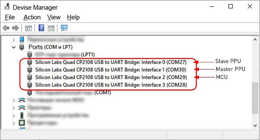
5

      The Master PPU is available through COM30 (Interface 1), the Slave PPU – through COM27 (Interface 0).
Port numbers could be different for alternative PC. Interface numbers could be different for alternative OEM-
module (see Table 2.1).

                Table 2.1 – Description of the NTL10X Interfaces
                  NTL10X            Interface numbers
                                                                       Description
                   family           (Virtual COM port)
                                Interface 1                 Master PPU (UART Tx/Rx line)
                   NTL101
                                Interface 2                 STM32H7 MCU
                   NTL102       Depends on adapter type     -
                   NTL103       Depends on adapter type     -
                                Interface 0                 Master PPU (UART Tx/Rx line)
                   NTL104
                                Interface 1                 STM32H7 MCU
                                Interface 0                 Slave PPU (UART Tx/Rx line)
                   NTL105       Interface 1                 Master PPU (UART Tx/Rx line)
                                Interface 2                 STM32H7 MCU
                                Interface 0                 Slave PPU (UART Tx/Rx line)
                   NTL106       Interface 1                 Master PPU (UART Tx/Rx line)
                                Interface 2                 STM32H7 MCU

      6. Run NTL Browser on computer. Then configure it:
         • Select interface language in the upper right corner of welcome page;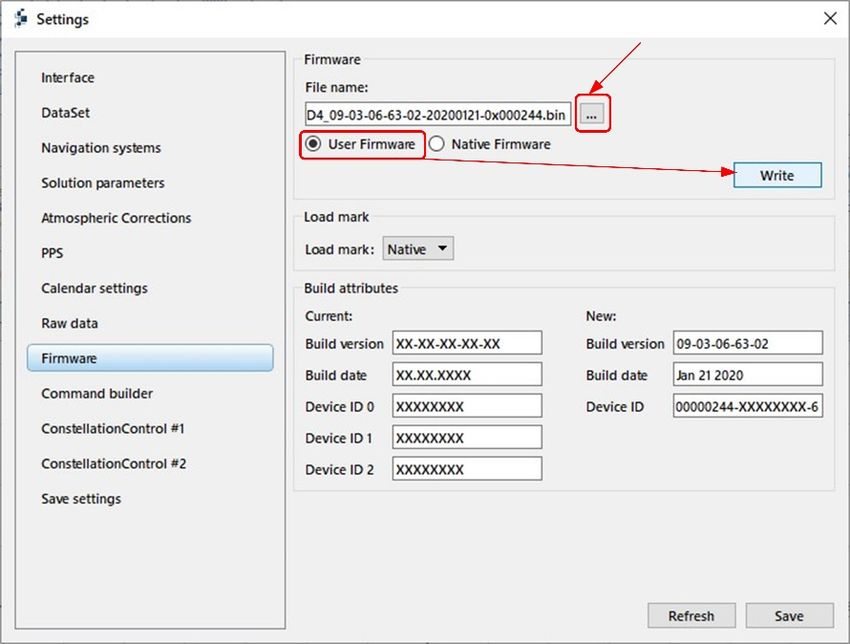
6
• Connect to the Master PPU * (COM30 Port);
• Set up 115200 Baud rate and NTL Binary Protocol type or Set up Auto detect ** checkbox to define
them automatically;
• Click on the Connect button to continue.
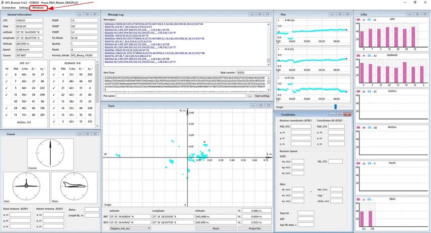
NTL Browser Main page consists of the multiple windows, that can be switched on/off in Windows
toolbar.
*
To upgrade firmware on NTL102 and NTL103, connect to one of the available COM port.
**Auto detect mode allows to setup connection with the receiver:
- baud rate would be scanned and selected automatically;
- protocol type would be set up to NTLBinary mode;
- current UART channel would be turned to ‘Master’ mode;
- raw data, if coming from this port, would be switched off.
If interfacing parameters are known in advance you may enter them manually and skip Auto detect.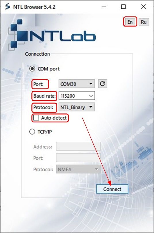
7

      7. Select the Settings/Show settings section.

      If you are in NMEA interface mode, you will be proposed to switch into NTL Binary. Click on the Yes
button.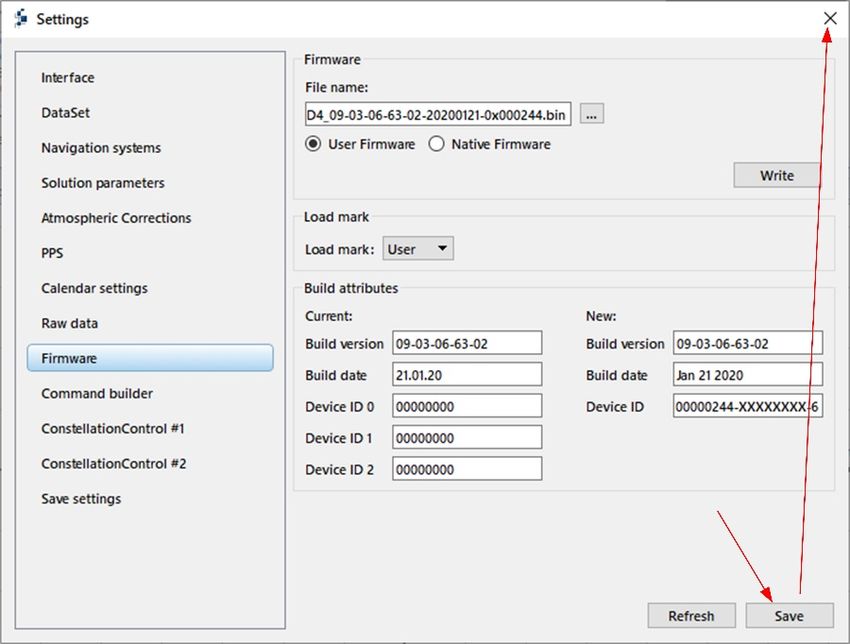
8

8. Then select the Firmware section.

   •     In the Firmware sub-section, select firmware file for master PPU as the File name. Then set
    User Firmware checkbox. Click on the Write button.

Loading and verification process takes some minutes.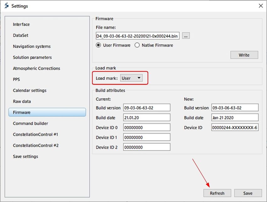
9

      Wait for completion.

      If connection is lost here, basic firmware file will be corrupted. In this case embedded firmware would
be loaded from backup section, Load mark would indicate Native.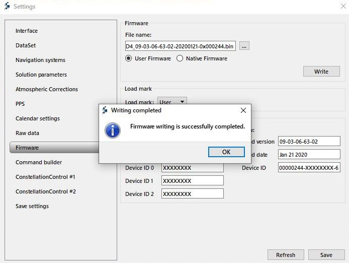
10

          •   Click on the Refresh button.

      Load mark will get User value automatically after successful completion of User Firmware Update
procedure. Though, this field is available for editing and firmware section to be loaded from may be selected
manually. To do this, setup Load mark and click on the Save button.

      9. Click on the Save button. Exit the Settings section.
11
10. Exit from NTL Browser. To do this, select Connection/Disconnect.
11. Restart the module.
12. Reconnect to the COM Port.
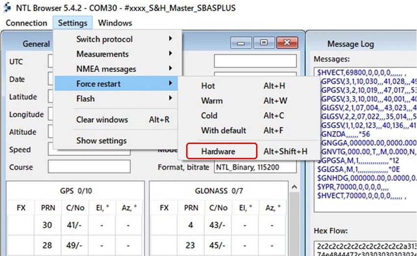
13. Make Restart to check new firmware version and build date. To do this, select Setting/Force
restart/Hardware.12
14. Exit from NTL Browser. To do this, select Connection/Disconnect.
15. Connect to the Interface 0 (COM27 Port) and repeat steps 7…14 to update Slave PPU firmware.
Use appropriate firmware file.13
3 JTAG PIN DEFINITION
Table 3.1 – XP4 connector (JTAG) pin definitions
Pin № Name I/O Description
1 3.3V Power Power supply voltage
2 JTRST Input Test Reset
3 TDI Input Test Data In
4 TMS Input Test Mode Select
5 TCK Input Test Clock
6 TDO Output Test Data Out
7 - - not connected
8 JSRST Input Reset
9 - - not connected
10 GND Power Signal and Power Ground14 CONTACT For complete contact information visit us at www.ntlab.com Head Office 4th floor, 41 Surganova str., 220013 Minsk, Republic of Belarus Tel.: +375 17 290 09 99 Fax: +375 17 290 98 98 e-mail: ntlab@ntlab.com, sales@ntlab.com EU Branch Office NTLAB, UAB Švenčionių g. 112, Nemenčinė, LT-15168 Vilniaus r., Lithuania Tel.: +370 6 169 5418 е-mail: sales@ntlab.lt
You can also read