Design of temperature acquisition and servo debugging board
←
→
Page content transcription
If your browser does not render page correctly, please read the page content below

E3S Web of Conferences 261, 02006 (2021)                                                            https://doi.org/10.1051/e3sconf/202126102006
ICEMEE 2021

         Design of temperature acquisition and servo debugging board
         Sun Yi1, Quanyu Sun1, *, and Guowei Shao1
         1
          Jiangsu Automation Research Institute, Lianyungang, Jiangsu, 222000, China

                      Abstract. The temperature acquisition and servo debugging board is used in Flight control computer,
                      mainly for temperature acquisition and servo debugging. Its good functional performance and reliability
                      have a good application prospect.

      1 Introduction
      Flight control computer is a computer for the application              3 Function
      of flight control system. Its main task is to complete
      control rate calculation, redundancy management and in-                3.1. Single Chip Micyoco
      flight self-test[1].
          The temperature acquisition and servo debugging                    Stm32f103zte6 of STM32 series of ST company is
      board is used in Flight control computer, mainly for                   selected as MCU.Stm32f103zet6 integrates abundant
      temperature acquisition and servo debugging.                           peripheral interfaces,512k byte flash program memory
                                                                             and 64K byte SRAM. With parallel LCD interface,
                                                                             compatible with 8080 /6800 mode. Power supply voltage
      2 Principle                                                            and IO voltage support 2.0-3.6v, embedded with 8MHz,
                                                                             40KHz,32kHz RC oscillator. It has 3 12 bit AD
      Temperature acquisition and servo debugging board
                                                                             converters, conversion range 0-3.6v,2-channel 12 bit DA
      debugging are composed of two functions: temperature
                                                                             converter. It has 12 channel DMA controller and
      acquisition and servo debugging board. The temperature
                                                                             supports timer, SDIO, I2C, SPI and other peripherals. It
      acquisition board collects analog signals input by 4
                                                                             has 11 timers and up to 13 communication channels:2
      thermocouples and 4 thermal resistance, converts them
                                                                             I2C interfaces (supporting SMBus/PMBus),5 USART
      into digital quantities and calculates the current
                                                                             interfaces (supporting ISO7816, Lin, IrDA interfaces and
      temperature values, which are transmitted to the upper
                                                                             modulation and demodulation control),3 SPI interfaces
      computer through CAN bus and temperature debugging
                                                                             (18m bit / s),2 reusable I2C interfaces,1 can interface
      serial port. The servo board debug function realizes the
                                                                             (2.0B active), USB 2.0 full speed interface and SDIO
      12 way servo debugging serial port and the whole
                                                                             interface
      machine debugging serial port's 12 selected 1 functions.
      The upper computer sends instructions or switch
      switches, selects the whole machine to debug the serial                3.2. External communication interface
      port and which servo debug serial port to connect, and
      feedback the serial port which is debugged through the                 a) One isolated can bus interface;
      can bus. The specific principle block diagram is shown                     b) One RS232 communication interface;
      in Figure 1.                                                               c) RS232 servo debugging interface of 1 out of 12;

                                                                             3.3. 8-way temperature acquisition function
                                                                             The temperature acquisition board collects the analog
                                                                             signals of 4 thermocouples and 4 thermistors, converts
                                                                             them into digital values and calculates the current
                                                                             temperature value.

         *
          Corresponding author’s e-mail: sunchuanyu7@126.com
© The Authors, published by EDP Sciences. This is an open access article distributed under the terms of the Creative Commons Attribution License 4.0
(http://creativecommons.org/licenses/by/4.0/).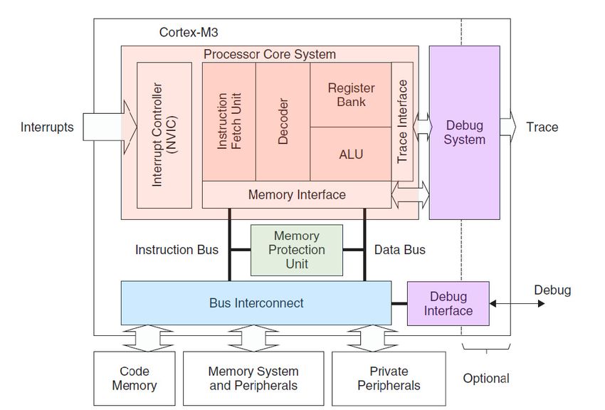
E3S Web of Conferences 261, 02006 (2021)                                                                               https://doi.org/10.1051/e3sconf/202126102006
ICEMEE 2021

                                                                 STM32F103ZTE6

                         Switching
                          control
                           signal                                                                 AD
                                                            CA          UA
                                                            N           RT                     converter
                                                                                                                             5V to 3.3V
                                                                                               Operational
                              Analog switch                                                   amplifier and
                                                                                               filter circuit
                                                                                                                    12V
                                                                                                                                12V to 5V
                                                             Can bus             RS232
                                                                                                                  to±15V
                                                            interface          interface
                                                              circuit            circuit

                                                                                              4-way             4
                     12 servo debugging   Servo debugging    Can bus         Temperature                                12V power
                                             port of the                      debugging     thermistor   thermocoup
                          serial port      whole machine    interface         serial port                                 input
                                                                                              input        le inputs

                                                              Fig. 1. Principle block diagram.

                                                                                             same memory space (a unified memory system), and
                                                                                             Figure 2 is a simplified view of cortex‐m3.
      3.4. Switching function
                                                                                                Stm32f103zet6 has 5-way UART interface and 1-
      The 12 servo debug serial port and the whole machine                                   way can bus interface. In this design, stm32f103zet6 is
      debug the serial port's 12 selected 1 functions. The upper                             used to realize the CAN bus, UART and AD acquisition
      computer sends instructions or switch switches, selects                                and communication functions of the module. The
      the whole machine to debug the serial port and which                                   specific implementation principle is shown in Figure 3.
      servo debug serial port to connect, and feedback the
      serial port which is debugged through the CAN bus.                                     4.2. Input analog signal control circuit
                                                                                             The multi-channel analog signal input selection circuit is
      4 Hardware design                                                                      composed of an 8-out-of-1 analog switch max307, which
                                                                                             completes single ended 8-way input and module self-test
      4.1. STM32 Circuit                                                                     input. The voltage input range can reach -17V~+17V,
                                                                                             meeting the signal input range. The selected A/D
      Stm32f103zet6 is a high performance processor based on                                 conversion chip has 0~5V,shown in Figure 4.
      cortex-m3 core. It can work at 72MHz maximum
      frequency, and can reach 1.25DMips/MHz(Dhrytone
      2.1)when the memory is accessed for 0 waiting period.                                  4.3. DC / DC isolated power supple
      Cortex-m3 is a 32-bit processor kernel. The internal data                              In this design, the ad switch and RS232 switch need to
      path is 32-bit, the register is 32-bit, and the memory                                 use ± 15V power supply, so ±15V power supply module
      interface is 32-bit.CM3 adopts Harvard structure, and                                  is required in this scheme. In the scheme, the 6W dc/dc
      has independent instruction bus and data bus, which can                                DC conversion module VFA of Guangzhou
      make the index and data access go hand in hand. In this                                jinshengyang Technology Co., Ltd. is selected_Mp-6w:
      way, data access no longer occupies instruction bus, thus                              isolation voltage>1500vdc, MTBF>1000000 hours, high
      improving performance. To achieve this feature, cm3                                    voltage stability, low ripple, wide temperature working
      contains several bus interfaces, each optimized for its                                conditions, the specific selection model vfa1215mp-6w:
      own application, and they can work in parallel. On the                                 output ±15V two-stage voltage, current ±200mA.
      other hand, the instruction bus and data bus share the

                                                                                       2
E3S Web of Conferences 261, 02006 (2021) https://doi.org/10.1051/e3sconf/202126102006
ICEMEE 2021
Fig. 2. Simplified view of cortex - M3
Fig. 3. STM32 Circuit.
.
3E3S Web of Conferences 261, 02006 (2021) https://doi.org/10.1051/e3sconf/202126102006
ICEMEE 2021
4.5. Isolated can bus interface circuit
4.4. Switching circuit Can interface of STM32 is used in an bus, and
pca82c250t chip is used to realize optocoupler isolation
The 12 channel RS232 switching circuit is composed of
of CAN bus interface, shown in Figure 5.
two 16 choose one analog switches max306 to complete
the switching of 12 channel RX and TX signal input and
output. The voltage input range can reach -17V~+17V,
meeting the RS232 signal input range.
Fig. 4. Schematic diagram of AD converter interface.
Fig. 5. Schematic diagram of CAN bus interface.
5 Conclusion
References
This board selects STM32 microcontroller as the control
core, PT100 platinum resistance as the temperature 1. W.S.Liu.(2013) Airborne computer technology [M].
sensor, which has the characteristics of high precision, Aviation Industry Press, Beijing.
low cost and strong anti-interference ability, meets the 2. Q.Lin.(2015) Design and implementation of
requirements of flight control computer for temperature distributed temperature acquisition system based on
acquisition, and has the function of 12 channel servo CAN bus [M].North University Of China.
serial port switching debugging, which has a broad 3. D.L.Gu, X.M.Xia, G.Zheng.(2005) Design of Flying
application prospect. Control System for an Autonomous Helicopter.
4E3S Web of Conferences 261, 02006 (2021) https://doi.org/10.1051/e3sconf/202126102006
ICEMEE 2021
Journal of Nanjing University of Aerinautics 5. S.Li,X.G.Tuo, G.Y.Zhang, L.Chen.(2018)Design of
&Astronautics, Vol.37No.4. multi channel temperature acquisition system based
4. X.Y., Dong, H.Y.Meng, L.B.Kong. (2018) on stm32.Journal of Sichuan University of Science
BasedontheSTM32ThermistorPartialPressureType & Engineering (Natural Science Edition), Vol. 31
Temperature Measuring System Design. No. 3:50-53.
Computer& Digital Engineering, Vol.46No.4:846-
850.
5You can also read