OPENPATH ACCESS CONTROL
SYSTEM INSTALLATION GUIDE
V2.0
←
→
Page content transcription
If your browser does not render page correctly, please read the page content below

OPENPATH ACCESS CONTROL SYSTEM INSTALLATION GUIDE V2.0

TABLE OF CONTENTS
  TABLE OF CONTENTS                                                   2
Openpath Access Control System Installation Guide                     4
  GETTING STARTED                                                     4
  ADDITIONAL RESOURCES                                                4
  PRIOR TO INSTALLATION                                               4
Installation                                                          5
  NETWORK REQUIREMENTS                                                5
  SELECTING A BACKUP BATTERY                                          5
  MOUNTING INSTRUCTIONS                                               6
    INSTALLING CORE SERIES BOARDS IN E1 ENCLOSURE                     6
    INSTALLING CORE SERIES BOARDS IN E2 ENCLOSURE                    10
  WIRING OPENPATH READERS                                            12
    WIRING INFORMATION                                               13
  STANDARD CONFIGURATIONS                                            14
    WIRING THE CORE SERIES 24V 4 DOOR SMART HUB                      14
    WIRING THE CORE SERIES 12/24V 4 DOOR SMART HUB                   14
    WIRING THE CORE SERIES 24V ELEVATOR SMART HUB                    15
    WIRING THE CORE SERIES 12/24V 8-DOOR SMART HUB                   16
    WIRING THE REX WITH THE DOOR STRIKE                              17
    WIRING THE REX WITH THE ELECTROMAGNETIC LOCK                     18
    WIRING FAIL SAFE AND FAIL SECURE LOCKING HARDWARE                19
  ADVANCED CONFIGURATIONS                                            19
    WIRING WIEGAND READERS TO OPENPATH READERS                       19
    WIRING TO LEGACY PANELS AND MOBILE GATEWAY                       19
    CHANGING I/O TYPES                                              20
    WIRING TO WIEGAND DEVICES ON CORE SERIES SMART HUBS              21
    END-OF-LINE SUPERVISION                                         23
Troubleshooting                                                     23
  ACU LEDS                                                          24
    CORE STATUS LED                                                 25
  READER LEDS                                                       25
  LEGACY WIRING                                                     27
  RESETTING THE ACU                                                 27
    SOFT RESET                                                      27
    HARD RESET                                                      27
  PROVISIONING THE ACU                                              28
    REQUIREMENTS                                                    28
    CREATE ACU                                                      28
    PROVISIONING STEPS                                              30
    TEST INTERNET CONNECTION                                        32
    NETWORK SETTINGS                                                32
Appendix: First Gen Smart Hubs                                      33
  SELECTING A BACKUP BATTERY                                        33
    INSTALLING 4 DOOR CONTROLLER WITH 24V LOCKING HARDWARE          33
    WIRING WITH THE 12/24V POWER SUPPLY                             34
    WIRING WITH THE 12V POWER SUPPLY                                36
    WIRING THE OPENPATH ELEVATOR BOARD TO A 4 DOOR CONTROLLER       37
    WIRING THE 4 DOOR CONTROLLER TO LEGACY PANELS                   38

Version 2.0              © Openpath 2021                        2
TROUBLESHOOTING                                39
   4 DOOR CONTROLLER LEDS                       40
REGULATORY                                      41
 UL 294                                         41
 CAN/ULC 60839-11-1-16 GRADE 1                  41
 FCC                                            41
 IEC 62368-1                                    42
 RF Radiation Hazard Warning                    42
 Industry Canada Notice and Marking             42
Warnings                                        43
Technical Specifications                        43

Version 2.0               © Openpath 2021   3
Openpath Access Control System Installation Guide
GETTING STARTED
This Installation Guide explains how to install and configure Openpath Smart Hubs
(ACUs) and Openpath Smart Readers as part of an Openpath Access Control system.
This guide includes information about Core Series Smart Hubs and first generation
Smart Hubs (See Appendix: First Gen Smart Hubs ). For information on the Single Door
Controller, refer to the Openpath SDC Install Guide.

ADDITIONAL RESOURCES
                                               l    24V Elevator Smart Hub Data Sheet
    l   Access Control Core Data Sheet
                                               l    Smart Reader Data Sheet
    l   4-Port Board Data Sheet
                                               l    First Gen Smart Hub Data Sheet
    l   8-Port Board Data Sheet
                                               l    Openpath User Guide
    l   16 I/O Elevator Board Data Sheet
                                               l    Single Door Controller Install Guide
    l   24V 4 Door Smart Hub Data Sheet
                                               l    Life Safety Power FPV Installation Guide
    l   12/24V 4-Door Smart Hub Data
        Sheet
                                               l    Life Safety Power B100 Installation
                                                    Guide
    l   12/24V 8-Door Smart Hub Data
        Sheet
                                               l    Life Safety Power C4/C8 Installation
                                                    Guide

PRIOR TO INSTALLATION
Prior to installing Openpath hardware, perform a customer site survey to determine
the following:

   l    How many entries need to be configured (e.g. doors, gates, and/or elevator
        floors)
   l    Whether you're using legacy wiring or new wiring
   l    What kind of electronic entry mechanisms, Request to Exit (REX) mechanisms,
        and door contact sensors will be used and their power requirements. If your
        locking hardware requires 24V, either use a Smart Hub with an included 24V
        power supply or use a separate 24V supply.

Version 2.0                       © Openpath 2021                                         4
l   Whether you're providing backup batteries for the ACUs. See SELECTING A
       BACKUP BATTERY .
   l   Whether you're supporting a legacy access control panel for mobile gateway.
       See WIRING TO LEGACY PANELS AND MOBILE GATEWAY.

Installation
NETWORK REQUIREMENTS
An Ethernet connection with DHCP must be used to connect the ACU to the Local Area
Network (LAN). You also need to configure firewall settings to communicate with the
Openpath system. Openpath uses the following outbound ports:

   l   TCP port 443
   l   UDP port 123

Note: If using an external DNS server, outbound UDP port 53 must also be open.

To support Wi-Fi unlocking from the mobile app, the ACU's inbound TCP port 443 must
be available from within the LAN. Inbound port forwarding on the router, firewall, or
NAT device is not required.

SELECTING A BACKUP BATTERY
While not required, Openpath recommends having a backup battery in case of power
outages. The size of battery depends on your setup and how long you want to power
the system.

                 Table 1 Power requirements for Core Series Smart Hubs (24V)

 Access Control Core                            0.4A

 4-Port Board                                   0.3A

 Smart Reader                                   0.14A

 Locking hardware (while engaged)               0.12A--0.25A

Assuming a 24V power supply, a Core Series Smart Hub configured with four
Openpath Readers and locking hardware uses about 2 Amps. To keep the system
running for 3 hours with all entries engaged, you need 2A x 3 hours = 6AH, so two 12V
6AH sealed lead acid (SLA) or gel cell batteries wired in series.

Version 2.0                      © Openpath 2021                                   5
MOUNTING INSTRUCTIONS
Openpath Smart Hubs use LifeSafety Power E1 and E2 enclosures. Core Series Smart
Hubs are shipped with power supplies pre-installed, but Openpath boards must be
installed separately.

To mount the enclosure to the wall:

  1.   (Optional) Remove the enclosure's cover
  2.   Locate the top keyhole mounting holes in the back of the enclosure
  3.   Mark and pre-drill the locations for the keyholes in the mounting surface
  4.   Partially install two fasteners appropriate for the surface on which the enclosure
       is being installed. Leave the heads of the fasteners approximately ¼" out from
     the surface. Minimum fastener size should be #10 or larger.
  5. Hang the enclosure on the two fasteners and mark the locations of the
     remaining mounting holes
  6. Remove the enclosure and pre-drill the locations for the remaining mounting
     holes
  7. Re-hang the enclosure on the top mounting fasteners, install the remaining
     fasteners and tighten all fasteners
  8. Reinstall the enclosure's cover, if removed in step 1

INSTALLING CORE SERIES BOARDS IN E1 ENCLOSURE

   1. Mount 4-Port in upper corner of enclosure by snapping board standoffs into
     holes in back of enclosure
  2. Mount Core Board below 4-Port, perpendicular to back of enclosure, by hooking
     tabs into holes in back of enclosure
  3. Mount Elevator/IO Board (if included) below the Core Board using 6-32 screws
     (insert screws from back of enclosure) with USB port on the left
  4. Connect Core Board to 4-Port Board with included USB cable. Connect Core
       Board to Elevator/IO Board with additional USB cable.
         a. Maximum recommended USB cable length: 6 feet (2 meters) or 10 feet (3
              meters) if high quality, shielded cable

Version 2.0                           © Openpath 2021                              6
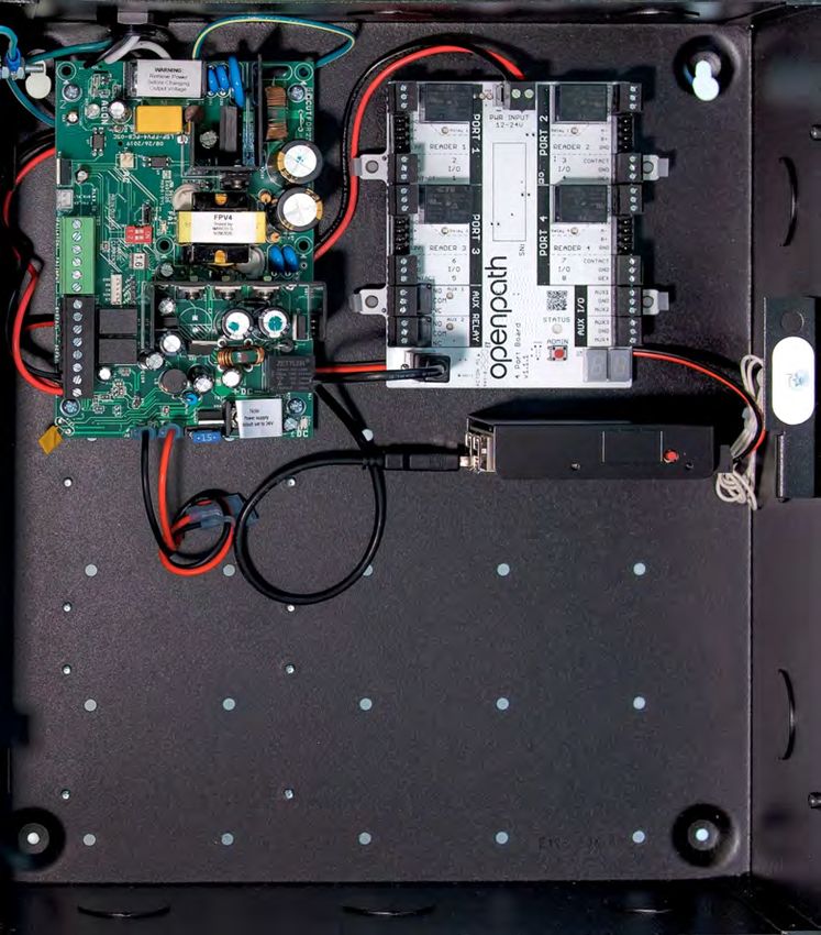
Figure 1 E1 Board Placement

Version 2.0   © Openpath 2021               7

Figure 2 4ENT-SYS-1224V Board Placement

Version 2.0          © Openpath 2021                    8

Figure 3 4ENT-SYS-24V Board Placement

Version 2.0         © Openpath 2021                   9

Figure 4 20ENT-SYS-24V Board Placement

INSTALLING CORE SERIES BOARDS IN E2 ENCLOSURE

   1. Mount 8-Port in upper right corner of enclosure by snapping board standoffs
     into holes in back of enclosure
  2. Mount Core Board with the USB and Ethernet ports facing up as shown in the
      diagram, and hook the tabs on into the holes in the enclosure and slide to the
     left to lock in place
  3. Connect Core Board to 8-Port with included USB cable
        a. Maximum recommended USB cable length: 6 feet (2 meters) or 10 feet (3
              meters) if high quality, shielded cable

Version 2.0                       © Openpath 2021                              10
Figure 5 E2 Board Placement Version 2.0 © Openpath 2021 11
Figure 6 20ENT-SYS-24V Board Placement

WIRING OPENPATH READERS
Openpath Readers and ACUs communicate via RS-485. The following wire types are
compatible, listed in the order of preference which impacts distance.

   l   Shielded CAT6A (recommended, additional two pairs can be used for sensors)
   l   Shielded CAT6
   l   Shielded RS485 w/22-24AWG (lower gauge, thicker wire is better)

Version 2.0                    © Openpath 2021                              12
l   Shielded CAT5
   l   Unshielded CAT6
   l   Unshielded CAT5
   l   Shielded 22/6
   l   Unshielded 22/6

Ideally, use one twisted pair for GND and VIN (power) and one twisted pair for +B and
-A (data).

WIRING INFORMATION

                         Figure 7 Smart Reader pigtail description

Recommended maximum cable length: 300 ft (91 m) with CAT6 or 500 ft (152 m) if
two wire pairs are used for GND and VIN (power).

For shielded wiring: Connect one side of the drain wire (the shield around the wires)
to the GND terminal on the ACU. Both the shield and the GND wire can share the same
GND terminal. Do not connect the other side of the shield to anything.

For standard reader installation: We recommend that you install a 1-Gang 20 CU
box in order to flush-mount the reader. Alternatively, the reader may also be surface
mounted with the included back plate.

Note: For elevators, all relays and readers must be connected to the same ACU. If you
need more than four access controlled floors or readers, add the Openpath Elevator
Expansion Module.

Version 2.0                    © Openpath 2021                                 13
WARNING: Always remove power from the ACU and locking hardware when wiring
readers and other devices. Failure to do so can damage the ACU.
STANDARD CONFIGURATIONS
WIRING THE CORE SERIES 24V 4 DOOR SMART HUB
The Core Series 24V 4 Door Smart Hub (4ENT-SYS-24V) uses an FPV4 to power the
Core and 4-Port Board.
Figure 8 4ENT-SYS-24V Wiring Diagram
WIRING THE CORE SERIES 12/24V 4 DOOR SMART HUB
The Core Series 12/24V 4 Door Smart Hub (4ENT-SYS-1224V) uses an FPV4 to power
the Core and 4-Port Board, a B100 secondary power supply, and a C4 Control
Module to power 12-24V locking hardware.
Version 2.0 © Openpath 2021 14Figure 9 4ENT-SYS-1224V Wiring Diagram WIRING THE CORE SERIES 24V ELEVATOR SMART HUB The Core Series 24V Elevator Smart Hub (20ENT-SYS-24V) uses an FPV4 to power the Core, 4-Port Board, and 16 I/O Elevator Board. Version 2.0 © Openpath 2021 15
Figure 10 20ENT-SYS-24V Wiring Diagram

ELEVATOR BUTTON WIRING

Interrupt one of the signal wires from each button and run through the C and NC
contacts for the corresponding relay on the 16 I/O Elevator Board.

GENERAL PURPOSE INPUTS

The general purpose inputs respond to voltages between 3V and 24V. The inputs will
not respond directly to a switch or relay connection to ground. To use these inputs
with a switch or relay, connect one side of the switch to the input and the other side of
the switch to a supply voltage between 3V and 24V. If desired, you can add a 1k ohm
resistor in series with the switch.

                                Figure 11 Elevator button wiring

WIRING THE CORE SERIES 12/24V 8-DOOR SMART HUB

The Core Series 12/24V 8-Door Smart Hub (8ENT-SYS-1224V) uses an FPV6 to power
the Core and 8-Port Board, a B100 secondary power supply, and a C8 Control
Module to power 12-24V locking hardware.

Version 2.0                       © Openpath 2021                                16
Figure 12 8ENT-SYS-1224V Wiring Diagram WIRING THE REX WITH THE DOOR STRIKE Except where required by fire or safety codes, for convenience you can wire the REX in parallel with the door strike on the same relay output. Version 2.0 © Openpath 2021 17
Figure 13 Wiring the REX with the door strike

WIRING THE REX WITH THE ELECTROMAGNETIC LOCK

For safety-related applications, you must wire the REX directly to the electromagnetic
lock.

                        Figure 14 Wiring the REX with the Mag Lock

Version 2.0                     © Openpath 2021                                18
WIRING FAIL SAFE AND FAIL SECURE LOCKING HARDWARE
Fail safe and fail secure are ways of configuring locking hardware:
l Fail safe hardware unlocks when power is interrupted
l Fail secure hardware locks when power is interrupted
ADVANCED CONFIGURATIONS
WIRING WIEGAND READERS TO OPENPATH READERS
To support additional card credentials, biometric scanners, and PIN codes, you can
wire third party readers to the Openpath ACU via the Smart Reader's pigtail. Simply
connect the power (red), ground (black), WD0 (green), and WD1 (white) from the
Smart Reader's pigtail to the Wiegand reader.
Figure 15 Wiring Wiegand Readers to Openpath Readers
WIRING TO LEGACY PANELS AND MOBILE GATEWAY
To add mobile credential features to a legacy access control system:
1. Install the Openpath ACU between the Openpath Readers and the legacy panel,
with the ACU's CHANGING I/O TYPES configured as output to the legacy panel
(see To configure Wiegand Devices in the Control Center:).
Version 2.0 © Openpath 2021 192. Replace low frequency (LF) Wiegand readers with LF Openpath Readers and
high frequency (HF) Wiegand readers with HF Openpath Readers, or replace
either with Smart Reader v2 which supports both.
Figure 16 Wiring ACUs to Legacy Panels
In this configuration, the legacy panel controls all locking hardware and entry
mechanisms while the Openpath system lets you use the Openpath mobile app,
Smart Reader, and Wave to Unlock functionality. Refer to the Openpath User Guide for
more information on configuring Mobile Gateway settings.
CHANGING I/O TYPES
While I/Os on the 4-Port and 8-Port Boards are labeled REX and CONTACT by default,
you can use these I/Os interchangeably or as generic inputs, by modifying their type
in the Control Center. You can also change them to Wiegand inputs, which requires a
few extra steps. See Configure Wiegand Devices in the Control Center.
To change input types in the Control Center:
1. Go to https://control.openpath.com/login and log in
2. Go to Hardware > ACU Management, then click on the ACU to edit it
3. Click on the Ports tab
Version 2.0 © Openpath 2021 204. Click Port next to the input you'd like to repurpose
5. Select a different type from the Input Type dropdown, then click Save
WIRING TO WIEGAND DEVICES ON CORE SERIES SMART HUBS
You can wire third party Wiegand readers and panels to the ACU to support
integrations or in the case of Mobile Gateway. The extra Auxiliary I/Os on the 4-Port
and 8-Port Boards are helpful for wiring Wiegand Devices, however any I/O pair may
be used (including Contact and REX inputs).
Figure 17 Wiring a Wiegand Device to a Core Series Smart Hub
To configure Wiegand Devices in the Control Center:
1. Go to control.openpath.com and log in
2. Go to Hardware > ACU Management, then click on the ACU to edit it
3. Click on the Ports tab
4. Click Port next to the first input of the I/O pair with a Wiegand device configured
(in example 1, Contact2; in example 2, AUX1)
5. Select Wiegand Device from the Input Type dropdown, then click Save
Version 2.0 © Openpath 2021 21This will label the subsequent input as Wiegand Device (Extended) and disable it from
editing. Inputs cannot be changed if they are already assigned to an entry.
Figure 18 Input settings in the Control Center
Once the Wiegand Device is configured on the ACU, it can be assigned to an Entry. Go
to Entry Management, then create or edit an existing entry. In the Wiegand Device
settings, configure the following:
l Port — select the port for the Wiegand Device to which this Entry is wired
l Mode — select the Mode to set which direction the card credential data is sent:
o Use Input to receive data from devices such as a Wiegand reader
o Use Output (Gateway) to send credential data to a third-party control
panel
n Enable Gateway Credential Pass-Through if you do not want
Openpath to authenticate credentials, but rather send all data to the
legacy panel for authentication
n Enter a Default Gateway Card Number so that all credentials
(including mobile credentials) are sent to the legacy panel as a
Wiegand ID
Figure 19 Assigning a Wiegand Device to an Entry
For more information on creating Entries, refer to the Openpath User Guide.
Version 2.0 © Openpath 2021 22END-OF-LINE SUPERVISION
4-Port and 8-Port Board inputs have support for user-installed single or double 1k
ohm termination. This lets you monitor cut or shorted lines and create alerts and rules
in the Control Center. The input settings in the Control Center must match the
physical wiring configurations.
Figure 20 EOL configurations and settings
To configure EOL in the Control Center:
1. Go to https://control.openpath.com/login and log in
2. Go to Hardware > ACU Management, then click on the ACU to edit it
3. Click on the Ports tab
4. Click Cable next to the port with EOL configured
5. Select the appropriate End of Line Supervision setting from the dropdown, then
click Save
Troubleshooting
l ACU LEDS
l READER LEDS
l LEGACY WIRING
l RESETTING THE ACU
l PROVISIONING THE ACU
Version 2.0 © Openpath 2021 23ACU LEDS
Figure 21 Expansion Board and Core LEDs
Openpath ACUs (Cores and Expansion Boards) have several LEDs that indicate the
following:
l POWER LEDs indicate that the board is connected to power
l RELAY LEDs indicate when the relays are activated
l STATUS LEDs indicate that the ACU has been configured with firmware.
o On the 4-Port and 8-Port Boards, the STATUS LED is solid green when it is
connected and communicating with the Core, and solid red when there is
a connection error
o If the STATUS LED is solid red, try the following:
n Power cycle 4-Port/8-Port
n Unplug and replug USB cable
Version 2.0 © Openpath 2021 24n Restart Hardware Communicator in Control Center
o The STATUS LED on the Core Board has several states, see CORE STATUS LED
l BOARD ID LEDs match the Expansion Board Number in the Control Center
CORE STATUS LED
The Core's STATUS LED indicates the following:
l Solid Green indicates the Core is provisioned and functioning normally
l Blinking Red indicates there is a problem with the Internet connection
l Solid Cyan appears when the Core is booting
l Solid Yellow indicates that the Core is restoring software; appears when you
power on the Core for the first time
l Blinking Yellow indicates that the Core is updating software; appears when the
Core has been online for less than 24 hours
l Solid Blue indicates that the Core has finished booting and is ready for
provisioning
l Solid Purple indicates that the Core is connected to the Open Admin app
l Blinking Purple indicates the Core is ready to connect to the Open Admin app
l Solid Red indicates the Core is in an error state--go to the Hardware Dashboard
in the Control Center for more information
Figure 22 Core Status LED Definitions
READER LEDS
The Openpath Smart Reader's LEDs indicate the following:
Version 2.0 © Openpath 2021 25center dot is solid
door is locked
white
outer ring is solid
door is unlocked
white
center dot quickly
switches between
multiple colors and reader has just received power
outer ring quickly
spins once
reader is not connected to power (check to see if
all lights are off
power wires are swapped)
reader is connected to power but cannot
center dot is flashing
communicate with the ACU (check to see if the
red
+B blue and -A violet lines are swapped)
reader is connected to power and can
center dot is solid
communicate with the ACU, but has not been
blue
configured as an entry in the Control Center
center dot is solid
green and the outer reader has been identified via the Control Center
ring is solid
reader is possibly not receiving enough voltage
center dot is solid
or current, potentially due to a break in wiring --
purple and the outer
try connecting the reader directly to the ACU,
ring is solid white
bypassing any wire runs
center dot is solid
check that +12V IN (orange) hasn't been
pink and the outer
swapped with +B (blue) or -A (violet)
ring is solid white
Version 2.0 © Openpath 2021 26LEGACY WIRING
Sometimes legacy wiring (unshielded and straight through, rather than shielded
twisted pair, often 22-6) results in slower connections and dropped packets between
the Openpath Reader and ACU. To remedy this, you can switch GND and VIN with +B
and -A connections on the ACU and readers to ensure the data pair (+B and -A) are
using the alternate pair of legacy wires.
RESETTING THE ACU
SOFT RESET
To soft reset the ACU, disconnect power from the ACU, wait 10 seconds, then
reconnect the power.
HARD RESET
WARNING: Only hard reset the ACU if absolutely necessary and if instructed by
Openpath. This will clear all of the data off of the ACUand will require
reprovisioning.
To hard reset the ACU:
1. Disconnect power from the ACU
2. Hold down the ADMIN button for 15 seconds
3. While still holding down the ADMIN button, reconnect the power, and continue to
hold the button for another 15 seconds, then release
4. Wait 15 minutes before PROVISIONING THE ACU
Figure 23 ADMIN button on Core
Version 2.0 © Openpath 2021 27PROVISIONING THE ACU
Provisioning the ACU means registering it in the Control Center and getting it up and
running with the latest firmware. You will need to re-provision in the case of RESETTING
THE ACU.
Note: If you're provisioning ACUs for a customer account, the customer org will need
to be created first.
REQUIREMENTS
l Meet all NETWORK REQUIREMENTS
l Connect the ACU to the Internet via Ethernet
l Install the Open Admin app
o iOS App Store
o Google Play Store
l If using a laptop instead of the app, the laptop must be on the same network as
the ACU. If you have a VLAN, make sure the laptop is on the same VLAN as the
ACU.
l If using a laptop running Windows or Linux, you must download iTunes. The
provisioning process uses Bonjour software that comes with iTunes. Optionally,
you can download iTunes and you an archive utility to extract and install only
the Bonjour MSI.
CREATE ACU
Before you can provision an ACU using the Open Admin app, you must first create an
ACU in the Control Center.
To add multiple ACUs with Quick Start:
1. Go to https://control.openpath.com/login and log in
2. Go to Administration > Quick Start
3. Enter a Site Name and any other relevant site information (optional), then click
Next
4. Enter how many controllers are located at your Site:
a. Enter names for the controllers
b. From the Controller Type dropdowns, select the appropriate types:
i. 4 Door Controller (OP-AS-01) — for first gen Smart Hubs
ii. Single Door Controller (SDC)
iii. Core Series ACU — for Core Series Smart Hubs
Version 2.0 © Openpath 2021 28c. Enter the number of expansion boards connected to the controllers, then
select the types used(Core Series Smart Hubs typically require at least one
expansion board):
i. Openpath 4-Port Expansion
ii. Openpath 8-Port Expansion
iii. Openpath 16-Port Elevator
d. Click Next
5. Enter how many Readers are connected to the controllers and enter names,
then click Next
6. Review your Site Details, then click Confirm & Submit. It may take a few minutes
for setup to complete.
To add one ACU
1. To add a new ACU, click the Add ACU button (+)
2. Enter a name for the ACU
3. From the Controller Type dropdown, select the appropriate type:
a. 4 Door Controller (OP-AS-01) — for first gen Smart Hubs
b. Single Door Controller (SDC)
c. Core Series ACU — for Core Series Smart Hubs
4. If your ACU also connects to an expansion board (this is most common with
Core Series Smart Hubs), then from the Add Expansion Board dropdown, select
and add the appropriate type(s):
a. Openpath 4-Port Expansion
b. Openpath 8-Port Expansion
c. Openpath 16-Port Elevator
5. A description will appear in green. Click Save.
Version 2.0 © Openpath 2021 29Figure 24 Create ACU
PROVISIONING STEPS
To provision the ACU with the Open Admin app (recommended):
1. Log into the Open Admin app with your Control Center credentials
2. Locate the org to which you're provisioning hardware, either on the list or using
search, then tap on the org name
3. Press the Admin button on the Controller Board or Core
4. In the Open Admin app, tap on the last four digits of the serial number for the
ACU
5. Tap Test Internet Connection and wait for a green YES to appear before
proceeding with the next step
a. Note: This checks if the ACU/SDC can ping
https://api.openpath.com/health
6. Tap Provision Device
7. Tap on the ACU Name that you want to provision to (this is the name of the ACU
you created in the Control Center), then tap Yes to proceed
8. The app will send notifications when ACU provision state changes from
Unprovisioned to Provisioning in progress to Provisioning complete
a. Note: ACU will disconnect from the Open Admin app 5 minutes after first
pressing the Admin button
Version 2.0 © Openpath 2021 30To provision the ACU with a laptop:
1. Using a computer that is on the same network as the ACU, go to
https://control.openpath.com and log in
2. Go to Hardware > ACU Management
3. Locate your ACU on the list
4. If you don't see your ACU listed, create a new one:
a. Click Add ACU and enter a name
b. Click on the Controller Type dropdown, select the appropriate type, and
add any expansion boards if necessary
c. Click Save
5. On the ACU, press the ADMIN button
6. In the Control Center, click the Register button (lightning icon) next to the name
of your ACU
7. Click Yes to proceed
8. A new window will open, click Provision
9. If you see a "This Site Cannot be Reached" error, you need to ping the ACU using
the command line:
a. Open a command prompt and run:
i. On Windows: ping oppi.local
ii. On Mac or Linux: ping -c4 oppi.local
l If nothing returns, check your network requirements. See
NETWORK REQUIREMENTS .
b. You should see the ACU's IP address (either in IPv4 or IPv6 format). Copy
the address and return to the error page.
c. In the URL, delete everything before :8080
i. If using an IPv4 address, paste before :8080. For example:
192.0.2.0:8080
ii. If using an IPv6 address, delete the last two digits and the
percentage sign, put square brackets outside the address, and paste
before :8080.
l Correct: a123::b456:5a18:eb8f:7fd6:8080
l Incorrect: a123::b456:5a18:eb8f:7fd6%29:8080
iii. Press Enter, then click the Provision button
iv. If the Provision button still doesn't appear, contact Openpath Support
at (844) 673-6728 Ext 2 or support@openpath.com.
Version 2.0 © Openpath 2021 31TEST INTERNET CONNECTION
In the Open Admin app, you can tap Test Internet Connection to check if the ACU
can ping https://api.openpath.com/health
NETWORK SETTINGS
In the Open Admin app, you can configure network settings for the ACU.
To change network settings:
1. Connect to the Core by pressing the Admin button again if needed
2. Tap on Network Settings
3. Select Configure network manually
4. Configure the network settings as needed — set a static IP address or set a
preferred DNS server
5. Tap Save on the top right of the screen
To set up Wi-Fi on the Core:
1. Connect to the Core by pressing the Admin button again if needed
2. Tap on Network Settings
3. Tap on Wi-Fi IP Settings
4. Enable Default Interface
5. Tap on Pick Wi-Fi Network
6. Choose your network and enter your password, then tap Connect
Version 2.0 © Openpath 2021 32Appendix: First Gen Smart Hubs
Openpath first generation hardware includes the 4 Door Controller (OP-4ECTR), 12V
Smart Hub (OP-SH-12V), and 24V Smart Hub (OP-SH-24V).
SELECTING A BACKUP BATTERY
Table 2 Power requirements for first gen Smart Hubs (12V)
4 Door Controller 1A
Smart Reader 0.25A
Locking hardware (while engaged) 0.25A--0.5A
Assuming a 12V power supply, a Smart Hub configured with four Openpath Readers
and locking hardware uses 4 Amps. To keep the system running for 3 hours with all
entries engaged, you need 4A x 3 hours = 12AH, so a 12V 12AH sealed lead acid (SLA) or
gel cell battery.
l Note: The 12V Smart Hub (OP-4ESH-12V) supports up to 2A for 12V locking
hardware.
INSTALLING 4 DOOR CONTROLLER WITH 24V LOCKING HARDWARE
For a UL Listed System, the standalone Controller Board must be mounted in a
LifeSafety Power E1 enclosure with an FPV4 power supply.
WARNING: Only connect the Controller Board to 12V. Over voltage can damage the
board.
If you purchased the Controller Board separately and are using 24V locking hardware,
we recommend using the LifeSafety Power E1 enclosure, FPV4 power supply, B100
secondary power supply, and C4 power control module.
1. Follow all LifeSafety Power instructions for installing the FPV4, B100, and C4 in the
enclosure
2. Mount the Controller Board using the provided back plate
3. Connect the B100 secondary supply to the Controller Board
IMPORTANT: Verify that the jumper on the B100 is set to 12V
Version 2.0 © Openpath 2021 334. Mount the enclosure according to MOUNTING INSTRUCTIONS above
Figure 25 First gen 12/24V Smart Hub configuration
WIRING WITH THE 12/24V POWER SUPPLY
The 12/24V Smart Hub ACU (OP-4ESH-24V) uses an FPV4 to power 24V locking
hardware, a B100 secondary power supply to power the ACU Board, and a C4 Control
Module to power 12V locking hardware.
Version 2.0 © Openpath 2021 34Figure 26 OP-4ESH-24V Wiring Diagram
All of this is configured as one Entry in the Openpath Control Center. We recommend
matching port numbers (READER 1 with CONTACT 1, for example). When setting up
Sites in the Control Center using Quick Start, Entries will default to matching READER 1
with CONTACT 1, RELAY 1, and so on. For more complex Entry setups, you'll need to
manually add Controls to the Entry. For the example above, you'd need to add an
additional Entry/Exit Hardware Control to the Entry. For more information, refer to the
Openpath User Guide.
This example contains:
l An Openpath Reader on READER 1 port (also connected to a Wiegand reader,
optional)
l A door contact sensor on CONTACT 1 port
l A REX on REX 1 port
l A 24V fail secure door strike on RELAY 3
l A 12V fail safe electromagnetic lock on RELAY 1
Version 2.0 © Openpath 2021 35WIRING WITH THE 12V POWER SUPPLY
Figure 27 OP-4ESH-12V Wiring Diagram
Version 2.0 © Openpath 2021 36WIRING THE OPENPATH ELEVATOR BOARD TO A 4 DOOR CONTROLLER
Figure 28 Wiring the Openpath Elevator Board to a 4 Door Controller
Version 2.0 © Openpath 2021 37WIRING THE 4 DOOR CONTROLLER TO LEGACY PANELS
Figure 29 Wiring to Legacy Panels
WARNING: Do not connect 12V out on the Wiegand port to the legacy panel; doing
this will cause voltage backfeeding, potentially damaging one of the supplies.
Version 2.0 © Openpath 2021 38TROUBLESHOOTING
Figure 30 ADMIN Button on 4 Door Controller
To hard reset the ACU:
1. Disconnect power from the ACU
2. Hold down the ADMIN button for 15 seconds
3. While still holding down the ADMIN button, reconnect the power, and continue to
hold the button for another 15 seconds. You should see two POWER LEDs light up
in the top left corner.
4. Wait 15 minutes before PROVISIONING THE ACU
Version 2.0 © Openpath 2021 394 DOOR CONTROLLER LEDS
Figure 31 4 Door Controller LEDs
l POWER LEDs indicate that the board is connected to power
l RELAY LEDs indicate when the relays are activated
l READER POWER LEDs indicate that the Controller has output power enabled per
reader
l The STATUS LED indicates that the Controller has been configured with firmware
Version 2.0 © Openpath 2021 40REGULATORY All national and local electrical codes apply. UL 294 The following performance levels are defined for the Core Series hardware and 4 Door Controller as per UL 294: Attack: Level I Endurance: Level I Line Security: Level I Standby: Level I CAN/ULC 60839-11-1-16 GRADE 1 For C-UL Listed applications, the unit shall be installed in accordance with Part 1 of the Canadian Electrical Code. FCC This device complies with part 15 of the FCC Rules. Operation is subject to the following two conditions: (1) This device may not cause harmful interference, and (2) this device must accept any interference received, including interference that may cause undesired operation. To comply with FCC RF exposure compliance requirements, a separation distance of at least 20 cm should be maintained between the antenna of Openpath Smart Reader(s) and persons during operation. NOTE: This equipment has been tested and found to comply with the limits for a Class A digital device, pursuant to part 15 of the FCC Rules. These limits are designed to provide reasonable protection against harmful interference when the equipment is operated in a commercial environment. This equipment generates, uses, and can radiate radio frequency energy and, if not installed and used in accordance with the instruction manual, may cause harmful interference to radio communications. Operation of this equipment in a residential area is likely to cause harmful interference in which case the User will be required to correct the interference at his own expense. OP-RLF-STD/MULB: FCC ID: 2APJVOPRLF OP-RHF-STD/MULB: FCC ID: 2APJVOPRHF Version 2.0 © Openpath 2021 41
OP-R2-STND: FCC ID: 2APJVOPR2LHF

OP-R2-MULL: FCC ID: 2APJVOPR2LHF

IEC 62368-1
   l   This equipment is intended only for use in a restricted access area.
   l   Securely fasten the equipment according to LifeSafety Power mounting
       instructions. See FlexPower Vantage Standard Power System - Installation
       Manual.
   l   PROTECTIVE EARTHING: For safety, the Smart Hub must only be plugged into a
       grounded 3-prong outlet, wired with a minimum of 16 gauge wire to ground.

RF Radiation Hazard Warning
To ensure compliance with FCC and Industry Canada RF exposure requirements, this
device must be installed in a location where the antennas of the device will have a
minimum distance of at least 20 cm from all persons. Using higher gain antennas
and types of antennas not certified for use with this product is not allowed. The device
shall not be co-located with another transmitter.

Installez l'appareil en veillant à conserver une distance d'au moins 20 cm entre les
éléments rayonnants et les personnes. Cet avertissement de sécurité est conforme
aux limites d'exposition définies par la norme CNR-102 at relative aux fréquences
radio.

Industry Canada Notice and Marking
Under Industry Canada regulations, this radio transmitter may only operate using an
antenna of a type and maximum (or lesser) gain approved for the transmitter by
Industry Canada. To reduce potential radio interference to other Users, the antenna
type and its gain should be so chosen that the equivalent isotropically radiated
power (e.i.r.p.) is not more than that necessary for successful communication.

Conformément à la réglementation d'Industrie Canada, le présent émetteur radio
peut fonctionner avec une antenne d'un type et d'un gain maximal (ou inférieur)
approuvé pour l'émetteur par Industrie Canada. Dans le but de réduire les risques de
brouillage radioélectrique à l'intention des autres utilisateurs, il faut choisir le type
d'antenne et son gain de sorte que la puissance isotrope rayonnée équivalente
(p.i.r.e.) ne dépasse pas l'intensité nécessaire à l'établissement d'une communication
satisfaisante.

Version 2.0                      © Openpath 2021                                    42
This device complies with Industry Canada licence-exempt RSS standard(s).
Operation is subject to the following two conditions: (1) this device may not cause
interference, and (2) this device must accept any interference, including interference
that may cause undesired operation of the device.
Le présent appareil est conforme aux CNR d'Industrie Canada applicables aux
appareils radio exempts de licence. L'exploitation est autorisée aux deux conditions
suivantes : (1) l'appareil ne doit pas produire de brouillage, et (2) l'utilisateur de
l'appareil doit accepter tout brouillage radioélectrique subi, même si le brouillage est
susceptible d'en compromettre le fonctionnement.
Warnings
l Disconnect power before servicing
l Do not plug into an outlet controlled by an on/off switch
l Powering power supply with 230V requires jumper modification, see power
supply data sheet for more information
Technical Specifications
Table 3 Technical specifications of Openpath hardware
Single Door Controller (OP-2ESH-POE) 12-24VDC, 0.3A @ 24V
12-24VDC, 0.25A @ 12V, 0.12A @ 24V
Smart Reader v2 (OP-R2-STND,
OP-R2-STND: FCC ID: 2APJVOPR2LHF
OP-R2-MULL)
OP-R2-MULL: FCC ID: 2APJVOPR2LHF
12VDC, 0.25A
OP-RLF-STD/MULB: FCC ID: 2APJVOPRLF
Smart Readers (OP-RLF-STD, OP-RHF-
STD, OP-RLF-MULB, OP-RHF-MULB, OP- OP-RHF-STD/MULB: FCC ID: 2APJVOPRHF
R2LHF-STD, OP-R2LHF-MUL)
OP-R2LHF-STD: FCC ID: 2APJVOPR2LHF
OP-R2LHF-MUL: FCC ID: 2APJVOPR2LHF
4 Door Controller (OP-AS-01/OP-4ECTR) 10-14VDC, 1A
16 I/O Elevator Board (OP-16EM) 12-24VDC, 0.35A @ 12V, 0.2 @ 24V
Version 2.0 © Openpath 2021 434-Port Board (OP-EX-4E) 12-24VDC, 0.4A @ 24V
8-Port Board (OP-EX-8E) 12-24VDC, 0.6A @ 24V
Access Control Core (OP-ACC) 12-24VDC, 0.4A @ 12V, 0.2A @ 24V
Smart Hub with 12/24V Supply (OP-4ESH-
120V, 0.7A or 230V, 0.3A, 50/60 Hz
24V)
Version 2.0 © Openpath 2021 44You can also read