Operating instructions - Battery-powered and LTE-based 2-channel district and local heating pipe monitoring device in the UMS network - BRUGG Pipes
←
→
Page content transcription
If your browser does not render page correctly, please read the page content below
Operating instructions

Battery-powered and LTE-based 2-channel
district and local heating pipe monitoring
device in the UMS network

BA 076354.020/01.21 CH
Page 2

Table of contents
Ordering information. .  .  .  .  .  .  .  .  .  .  .  .  .  .  .  .  .  .  .  .  .  .  .  .  .  .  .  .  .  .  .  .  .  .  .  .  .  .  .  .  .  .  .  .  . 3
Technical data .  .  .  .  .  .  .  .  .  .  .  .  .  .  .  .  .  .  .  .  .  .  .  .  .  .  .  .  .  .  .  .  .  .  .  .  .  .  .  .  .  .  .  .  .  .  .  .  .  .  . 3
General information .  .  .  .  .  .  .  .  .  .  .  .  .  .  .  .  .  .  .  .  .  .  .  .  .  .  .  .  .  .  .  .  .  .  .  .  .  .  .  .  .  .  .  .  .  . 4
Proper use .  .  .  .  .  .  .  .  .  .  .  .  .  .  .  .  .  .  .  .  .  .  .  .  .  .  .  .  .  .  .  .  .  .  .  .  .  .  .  .  .  .  .  .  .  .  .  .  .  .  .  .  .  . 4
Safety instructions .  .  .  .  .  .  .  .  .  .  .  .  .  .  .  .  .  .  .  .  .  .  .  .  .  .  .  .  .  .  .  .  .  .  .  .  .  .  .  .  .  .  .  .  .  .  . 4
Battery disposal. .  .  .  .  .  .  .  .  .  .  .  .  .  .  .  .  .  .  .  .  .  .  .  .  .  .  .  .  .  .  .  .  .  .  .  .  .  .  .  .  .  .  .  .  .  .  .  .  . 5
Installation.  .  .  .  .  .  .  .  .  .  .  .  .  .  .  .  .  .  .  .  .  .  .  .  .  .  .  .  .  .  .  .  .  .  .  .  .  .  .  .  .  .  .  .  .  .  .  .  .  .  .  .  .  . 5
   Mounting. .  .  .  .  .  .  .  .  .  .  .  .  .  .  .  .  .  .  .  .  .  .  .  .  .  .  .  .  .  .  .  .  .  .  .  .  .  .  .  .  .  .  .  .  .  .  .  .  .  .  .  . 6
   Electrical connection. .  .  .  .  .  .  .  .  .  .  .  .  .  .  .  .  .  .  .  .  .  .  .  .  .  .  .  .  .  .  .  .  .  .  .  .  .  .  .  .  .  . 6
   Test lead connection.  .  .  .  .  .  .  .  .  .  .  .  .  .  .  .  .  .  .  .  .  .  .  .  .  .  .  .  .  .  .  .  .  .  .  .  .  .  .  .  .  .  . 6
Function/Commissioning.  .  .  .  .  .  .  .  .  .  .  .  .  .  .  .  .  .  .  .  .  .  .  .  .  .  .  .  .  .  .  .  .  .  .  .  .  .  .  .  .  . 6
   Display and control field.  .  .  .  .  .  .  .  .  .  .  .  .  .  .  .  .  .  .  .  .  .  .  .  .  .  .  .  .  .  .  .  .  .  .  .  .  .  .  . 7
   Commissioning .  .  .  .  .  .  .  .  .  .  .  .  .  .  .  .  .  .  .  .  .  .  .  .  .  .  .  .  .  .  .  .  .  .  .  .  .  .  .  .  .  .  .  .  .  .  . 7
       Connecting measuring cable. . . . . . . . . . . . . . . . . . . . . . . . . . . . . . . . . . .  8
       Configuring LEAKGUARD CLOUD . . . . . . . . . . . . . . . . . . . . . . . . . . . . . .  9
       Antenna placement . . . . . . . . . . . . . . . . . . . . . . . . . . . . . . . . . . . . . . . . . .  9
       LEAKGUARD CLOUD factory settings . . . . . . . . . . . . . . . . . . . . . . . . . . .  9
   LEAKGUARD CLOUD function.  .  .  .  .  .  .  .  .  .  .  .  .  .  .  .  .  .  .  .  .  .  .  .  .  .  .  .  .  .  .  .  .  .  . 9
       Automatic operation . . . . . . . . . . . . . . . . . . . . . . . . . . . . . . . . . . . . . . . .  10
       Manual operation/Real-time measurement. . . . . . . . . . . . . . . . . . . . . . .  10
   Starting configuration.  .  .  .  .  .  .  .  .  .  .  .  .  .  .  .  .  .  .  .  .  .  .  .  .  .  .  .  .  .  .  .  .  .  .  .  .  .  .  .  . 12
   The LGKonfigurator program.  .  .  .  .  .  .  .  .  .  .  .  .  .  .  .  .  .  .  .  .  .  .  .  .  .  .  .  .  .  .  .  .  .  . 12
       Resetting password. . . . . . . . . . . . . . . . . . . . . . . . . . . . . . . . . . . . . . . . .  13
       Device configuration . . . . . . . . . . . . . . . . . . . . . . . . . . . . . . . . . . . . . . . .  14
       “Channel 1, channel 2” tab. . . . . . . . . . . . . . . . . . . . . . . . . . . . . . . . . . .  14
       “Temp., C1, C2” tab. . . . . . . . . . . . . . . . . . . . . . . . . . . . . . . . . . . . . . . . .  15
       Measured value memory tab. . . . . . . . . . . . . . . . . . . . . . . . . . . . . . . . . .  16
       COM parameters tab. . . . . . . . . . . . . . . . . . . . . . . . . . . . . . . . . . . . . . . .  17
       Time/Date tab . . . . . . . . . . . . . . . . . . . . . . . . . . . . . . . . . . . . . . . . . . . . .  18
       System tab. . . . . . . . . . . . . . . . . . . . . . . . . . . . . . . . . . . . . . . . . . . . . . . .  19
       Saving / Loading device configuration . . . . . . . . . . . . . . . . . . . . . . . . . .  23
   Changing battery.  .  .  .  .  .  .  .  .  .  .  .  .  .  .  .  .  .  .  .  .  .  .  .  .  .  .  .  .  .  .  .  .  .  .  .  .  .  .  .  .  .  .  .  . 27
       Battery error message. . . . . . . . . . . . . . . . . . . . . . . . . . . . . . . . . . . . . . .  27
   Battery disposal.  .  .  .  .  .  .  .  .  .  .  .  .  .  .  .  .  .  .  .  .  .  .  .  .  .  .  .  .  .  .  .  .  .  .  .  .  .  .  .  .  .  .  .  .  . 27
UMS server .  .  .  .  .  .  .  .  .  .  .  .  .  .  .  .  .  .  .  .  .  .  .  .  .  .  .  .  .  .  .  .  .  .  .  .  .  .  .  .  .  .  .  .  .  .  .  .  .  .  .  . 28
Compliance statement for modem.  .  .  .  .  .  .  .  .  .  .  .  .  .  .  .  .  .  .  .  .  .  .  .  .  .  .  .  .  .  .  .  . 29
EU Declaration of Conformity for LEAKGUARD CLOUD .  .  .  .  .  .  .  .  .  .  .  .  .  .  . 32

                 Important!
                 All safety instructions must be read and observed before commis-
                  sioning!

© 2021 BRUGG Rohrsystem AG. This operating manual may not be repro-
duced or made available to third parties, either in whole or in part, without spe-
cial permission from BRUGG Rohrsystem AG.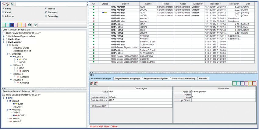
Page 3

Technical data
                                      LEAKGUARD CLOUD
Supply voltage                        Replaceable lithium battery, 3.6 V
Battery life                          > 5 years (with daily measurement and weekly status report)
Number of measurement channels        2 (e.g. for flow and return of a district heating line)
Insulation measuring range            0 .. 10 MΩ
                                      Error: 3% from measured value ±10 kΩ absolute

Loop measuring range                  0 .. 19.99 kΩ
                                      Error: 3% from measured value ±0.02kΩ absolute

Measuring section                     Brandes # 3,000 m, Nordic # 3,000 m
Length calculation                    Yes, for NiCr
Measurement voltage                   12 V DC
Display	1 LED bar display per measurement channel for “ISO
         measured value”
         1 LED per measurement channel for “Loop fault”, “ISO fault”
         and 2 “Contact status” signal LEDs, 6 status LEDs
On-site operation	1 button for real-time measurement with measured value
                   display and test message dispatch
Interfaces	1 USB interface for device configuration
            Limit value setting and measured value readout
            2 contact inputs (cable length max. 10 m)
Operating temperature                 -20 °C .. +50 °C
Permissible humidity                  0 .. 100%
Housing protection class              IP 66
Application area	Indoors and protected outdoor installation according to
                  DIN VDE 0100 Section 737
                  Residential and commercial areas as well as for small
                  businesses
Housing measurements                  180 x 180 x 100 mm (W x H x D)

Ordering information
Battery-powered 2-channel district and local heating pipe monitoring device
with LTE/GSM-based alarms in the UMS network, pipe connection monitoring
system, display field and 2 contact inputs
LEAKGUARD CLOUD              (max. measuring section NiCr/Cu 3,000 m)              Order no. 1088866
Spare part
 Lithium battery        3.6 V with holder and connection cable                     Order no. 1089454
Page 4

General
These operating instructions are intended to make it easier to familiarise your-
self with the product. They contain important information on how to use the
product safely, properly and economically.
The operating instructions must be supplemented with instructions based
on existing national regulations for accident prevention and environmental
protection.

         The operating instructions must be read and followed by every
         person who is entrusted with working with/on the device, e.g. dur-
         ing installation, maintenance and troubleshooting.

In addition to the operating instructions and the binding accident prevention
regulations applicable in the country of use and at the place of use, the rec-
ognised technical regulations for safe and professional work must also be
observed.

Proper use
The LEAKGUARD CLOUD district heating monitoring device is designed for
measuring insulation and loop resistance to detect leaks in pipe systems and
sending alarms via a mobile connection (LTE/GSM).
For configuration, the device can be connected to a PC (laptop) via the USB
interface.
Any other use is considered improper. The manufacturer is not liable for any
damage resulting from this; the risk is borne solely by the user!
Page 5

Safety instructions
       Important!
       Safety instructions must be read and observed before
       commissioning!

       • The operating instructions must always be available at the place of
         use of the product.
       • Only use the device in a technically perfect condition, as well as for its
         intended purpose, in a safety-conscious and risk-conscious manner
         and in compliance with the operating instructions.
       • Do not make any changes to the device.
       • Assembly, maintenance and repair work may only be carried out by
         trained staff.
       • Only use original BRUGG spare parts.
       CAUTION!
       Observe handling instructions.
       Electrostatically sensitive components.

       CAUTION!
       The installation location of the device should have an overall
       lightning protection concept which considers the power supply as
       well as data and telecommunication lines.

       CAUTION!
       Never apply external voltages to the test leads.

       CAUTION! Lithium battery!
       Only use original battery 3.6 V / 19 Ah with holder and connection
       cable. Never charge, reverse polarity of or short circuit a lithium
       battery.
       If necessary, observe shipping instructions for lithium batteries
       (Class 9, UN3090 or UN 3091).

Battery disposal
• Do not dispose of empty or defective
  lithium batteries with normal household waste!
• Observe the regulations of the Battery
  Directive.
• Bring empty or defective lithium batteries to a
  battery collection point.
Page 6
Installation
Mounting
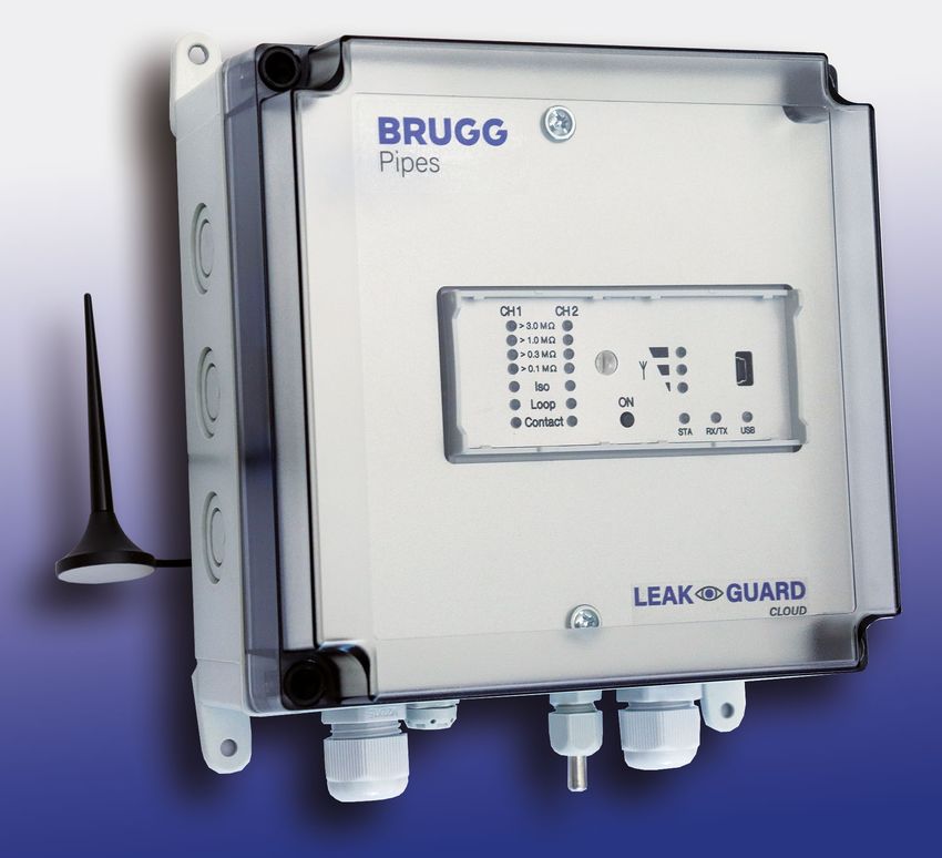
The LEAKGUARD CLOUD is situated in a wall-mounted housing and is
attached to the wall with four wall brackets and screws.
Electrical connection
The LEAKGUARD CLOUD is powered by a battery that is installed at the factory
but not yet connected.
Test lead connection
CAUTION!
Both pipe connection clamps X3.3 and X4.3 must be connected to
a pipe at two separate points, or one clamp must be connected to
the flow pipe and one clamp to the return pipe.
Pin assignment
X1
Antenna cable Channel 1 Channel 2
X2.1 to X2.3
Measurement loop channel 1
(a, b, pipe connection 1)
X3.1 to X3.3
Measurement loop channel 2
(a, b, pipe connection 2)
X4
Battery connection,
reverse polarity protected plug
contact
X5.1 to X5.2
Contact input 1
X6.1 to X6.2
Contact input 2
X7
Temperature sensor input
X8
Mini-USB 2.0 interface
Page 7

Function/Commissioning
The LEAKGUARD CLOUD is a measurement and monitoring device for insula-
tion and loop resistance for detecting leaks in pipe systems and interruptions
of the measurement loop as well as for monitoring potential-free contacts (e.g.
float switches).
Each device can cyclically monitor two measurement loops, e.g. the flow and
return of a district heating pipe. When exceeding or falling below the freely
adjustable resistance limit values, the red alarm LEDs are activated and an
alarm message is sent to the UMS server. No monitoring takes place between
the measurement cycles.
The LEAKGUARD CLOUD is equipped with a pipe connection monitoring sys-
tem to detect an interruption of the pipe connection (earth).
Two inputs are available for monitoring potential-free contacts. The contact sta-
tus (open/closed) is queried every 10 seconds.
The limit values for insulation and loop resistance as well as the contact set-
tings are freely programmable via the USB interface using a laptop/netbook. All
settings are stored in an internal EEPROM memory so they are protected from
loss.

Display and control field
In the LEAKGUARD CLOUD display and control field, you can
• Read off the values of the two insulation resistance measurement channels
   via the ISO bar display LEDs
• Read off the alarm states of the two insulation resistance measurement
   channels and interruptions of the pipe connection via the ISO LEDs
• Read the alarm states of the two loop resistance measurement channels via
   the Loop LEDs
• Read off the status of the contacts with the Contact LEDs
• Manually trigger real-time measure-             ISO bar display LED
                                                     Contact LED
   ment via the ON button
                                                     Loop LED
• Read off the status with the STA LED               ISO LED
• Read off the mobile network strength
   via three LEDs
• Read off the communication status
   via the RX/TX LED
• Determine the correct USB connec-
   tion via the “USB” LED
                                        Button for real-time measurement
• Process limit values                  Status LED
   with a laptop/notebook               Mobile network strength
   via the USB interface                Communication LED
                                        USB 2.0 interface with LED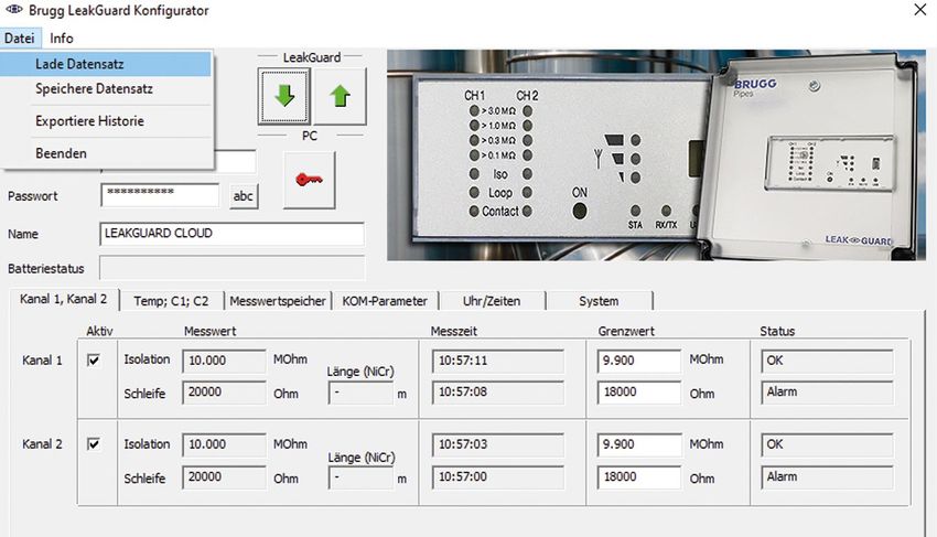
Page 8

Commissioning
The LEAKGUARD CLOUD is delivered from the factory with
the battery pre-assembled.
Connecting measuring cable
1.	 Install temperature sensor PT1000
    and connect.
    To do so, open the housing of the
    LEAKGUARD CLOUD: Unscrew the 4
    screws on the housing corners and lift
    the housing cover.
    Loosen the “C” screws of the panel and
    remove panel.
    Mount cable gland M12 in hole 1 and
    insert the sleeve of the temperature sensor
    into the cable gland. The sleeve should
    project approx. 1 cm from the screw
    connection.
    Put the measuring cable of the temperature
    sensor away below the module and
    connect to X7 (see page 6).                             2       1

2.	 Install breathing cap for pressure compensation.
    The screw plug ensures pressure compensation in the event of temperature
    fluctuations, preventing the penetration of moisture.
    Insert screw plug from the outside through hole 2 and tighten with enclosed
    union nut.

2.	 Connecting measuring cable
    Depending on the number of cables to be connected, make enough cut-outs
    for the cable glands and mount them.
    If not otherwise requested, the left cable gland is provided for the district
    heating pipe monitoring system, the middle one for contact monitoring. The
    seals for the bushings have 2 openings each. Three blind plugs are available
    to close unused openings.
    Tighten all bushings so they are tight.

3.	 Connecting antenna
    The right cable gland is intended for the antenna. The slotted seal must be
    used.
    Attach the plug of the antenna cable to antenna connection X1 (see page 6)
    of the LEAKGUARD CLOUD and tighten the union nut.

Tighten all bushings so they are tight.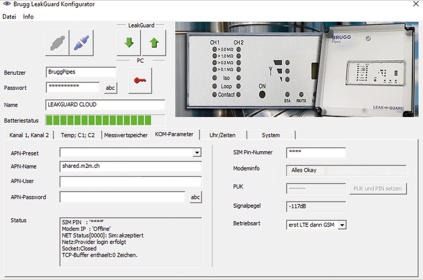
Page 9

Connecting lithium battery
Attach the reverse polarity protected battery plug (B) of the pre-assembled bat-
tery (A) to connection X4 (see page 6).

Inserting SIM card
The SIM card from a mobile provider is required to establish a connection to the
mobile network.
Caution: There are additional costs for the
mobile connection!
The housing must be opened to insert the
SIM card. To do so, unscrew the 4 screws
on the housing corners and lift the hous-
ing cover.
The compartment for the SIM card is
located at the bottom of the LEAKGUARD
CLOUD2-LTE/UMS module. There is only
one way to insert the SIM card into the
SIM compartment on the correct side:
With the bevel on the front left.
Then close the housing             SIM card
cover and screw it tight.

Configuring LEAKGUARD CLOUD
The LEAKGUARD CLOUD must be configured before commissioning. This con-
cerns the station name, limit values, UMS server with communication channel,
date, time and the daily measuring time (wake-up time). Configuration is car-
ried out via the USB connection using a laptop/netbook on which the supplied
"LGKonfigurator" software has been installed (see page 12).

Antenna placement

The antenna for the mobile phone connec-
tion can be mounted by means of a mag-
netic base on metallic surfaces or using
the supplied self-adhesive metal plate,
e.g. on the device housing.
The antenna is equipped with a 2 m cable for positioning in a suitable place
with good reception characteristics.

LEAKGUARD CLOUD factory settings
• Insulation resistance limit values (ISO): Alarm signal when undershooting 0,5 MΩ
• Loop resistance limit values (Loop): Alarm signal when exceeding 12 MΩ
• Contacts: Closed, no alarm
Page 10

LEAKGUARD CLOUD function
Automatic operation
After configuration, the LEAKGUARD CLOUD measurement device works auto-
matically and independently of external power sources.
It is mainly in "sleep mode", in which the contacts are scanned only every 10
seconds and the internal clock is operated to minimise power consumption.
At the programmed wake-up time (see page 15), the device becomes active
and performs a measurement cycle. This consists of
• Measurement of the two contact inputs
• Checking the earth connection
• Measurement of measurement channel 1 and 2 and
• Evaluation of the measurement results
If the LEAKGUARD CLOUD detects at least one error case, its integrated LTE/
GSM modem sends an alarm message to the UMS server and simultaneously
transmits all current measured values as well as all entries from the history that
have not yet been transmitted to the UMS server.
Then the device stores the current measured values as acknowledged in the
history and returns to "sleep mode". At the next programmed wake-up time, a
measurement cycle is started again and the measured values are stored in the
history. If an error occurs, the device proceeds as described above.

Manual operation/Real-time measurement
On site, the operator can activate the device by briefly pressing the "ON" but-
ton and read the status of the device via the LEDs. No message is sent.
By pressing the ON button for at least 5 seconds, a connection to the UMS
server is also established, the current measured values marked as "test meas-
urement" and all entries from the history that have not yet been transmitted to
the UMS server are sent.
A. Briefly pressing the "ON" button
1. Indicates the status of the contact inputs on the “Contact CH1” and
   “Contact CH2” LEDs.
  Red = “Alarm” contact status, Green = “OK” contact status.
2. Then the measurement cycle starts and displays the measurement results
   one after the other. Sequence: LOOP1, ISO1, LOOP2, ISO2.
Page 11

   Meaning of the LEDs in real-time measurement
a. The “ISO 1” and “ISO 2” LEDs show          ISO bar display LED
   the range in which the current meas-         Contact LED
   ured values are located:                     Loop LED
                                                ISO LED
   > 0.1 | > 0.3 | >1 | > 3 MΩ.
b. The “ISO 1” and “ISO 2” error LEDs
   change from green to red when the
   defined limit value is undercut.
   They flash alternately if
   the pipe connection is interrupted.
c. The “LOOP 1” and “LOOP 2”                Button for real-time measurement
                                            Status LED
   error LEDs change from green
                                            Mobile network strength
   to red when the measurement loop         Communication LED
   has been interrupted and the defined     USB 2.0 interface with LED
   limit value has been exceeded.
d. The “Contact 1” and “Contact 2” LEDs change from green to red when the
   switching state has changed.
3. The device then automatically goes into "sleep mode".

B. Holding the "ON" button down for 5 seconds
If you hold down the button for at least 5s until the lower LED of the field strength
bar display lights up, first the measurement cycle described above is run through
and then a status message is sent: The current measured values marked as "test
measurement" and all entries from the history that have not yet been transmitted
to the UMS server.
Meaning of the LEDs when sending the status message to the UMS server:
Establishing a connection to the mobile station

The lowest LED of the field strength bar display lights up.
Shortly afterwards, it goes out and the top LED of the field strength bar display
lights up green until a connection to the mobile station has been established.
After that, the LEDs of the field strength bar display show the connection level.
Data transmission to the mobile station
The “Rx/Tx” LED flashes.
The LEDs of the field strength bar display indicate the quality of the connection.
1 LED = Weak reception
2 LEDs = Good reception
3 LEDs = Very poor reception
Terminating the data transmission to the mobile station
The LEDs of the field strength bar display go out
The “Rx/Tx” LED lights up briefly once again
All LEDs go out and the device returns to “sleep mode”.
Meaning of status LED:
• The status LED lights up red if it was not possible to send a message. After
  sending a message is successful, it lights up green again.
Page 12 LEAKGUARD CLOUD configuration To change the factory setting or to adjust the parameters later, a computer (lap- top, notebook, netbook | Windows 7 and higher) must be connected to the LEAKGUARD CLOUD via the USB 2.0 interface. The "LGKonfigurator" program must be available on the com- puter. All files on the supplied USB stick must be copied into a directory for this purpose. The drivers for the LEAKGUARD CLOUD are also located here, if it is not automatically recognised when connected to the USB cable. Starting configuration 1. Connect the computer to the LEAKGUARD CLOUD using the supplied USB cable. 2. On the computer in the appropriate directory, start the "LGKonfigurator" program with a double click. The LGKonfigurator program After starting the “LGKonfigurator” program and wiring the LEAKGUARD CLOUD, the following screen appears: Access to the device is password-protected. In the delivery state, the following access data applies (already entered): User: BRUGG password: Pipes The password can be made visible by clicking on . Clicking on connects the software to LEAKGUARD CLOUD. The data stored in the device is retrieved automatically. The key icon to the right of the login fields turns red .
Page 13

Changing password
To protect against unauthorised access, the device must be protected by
assigning a new user name and password.
To change the user name and password
1. Enter new user name (overwrite         User name and password
   “BRUGG”)*
                                          Permissible character lengths
2. Enter new password                     User:     2 - 20 characters
   (write over “••••••”)*                 Password: 8 - 20 characters
   The user names and passwords           Permissible characters
   "reset" and "BRUGG" are reserved       a-z, A-Z, 0-9, !“#$%&‘()*+,-./:;< >?@,
   for certain functions and are there-   No spaces, umlauts and ß
   fore locked.
3. Note both for later access
4. Press red key icon
5. Confirm security query for accidental overwriting by clicking the "OK" button.

The new entries are accepted and saved. The connection to the device is dis-
connected and must be re-established by clicking on     .

Access to the device is now only possible with the current user name and
password.
Comfort function
As long as the LGKonfigurator has not been closed, the input fields "User" and
"Password" show the last entries.
Note
User name and password are not stored outside the device. This means that
they are not considered for the "Load data set" and "Save data set" functions
(see p. 24).
Page 14 Resetting password If the user name and password have been forgotten, the device can be reset to the factory settings. All data worthy of protection such as APN-Name, APN- Password, PIN number, etc. are deleted and must be re-entered afterwards. Resetting is done by entering user name "reset" and password "reset" and then clicking on the key icon . Then you can login with user name "BRUGG" and password "Pipes". Device configuration After entering the user name and password, clicking on connects the soft- ware to LEAKGUARD CLOUD. The data stored in the device is retrieved automatically. The key icon to the right of the login field turns red . The freely selectable device name appears in the "Name" field and can also be changed later: The remaining energy of the device battery can be read off in the “Battery sta- tus” field. A new battery has a lifetime of approx. 5 years with daily measure- ments and weekly status reports: The "Channel 1, Channel 2", "Temp; C1; C2", "Measured value memory", "COM parameters", "Clock/Times" and "System" tabs can be used to make further settings.
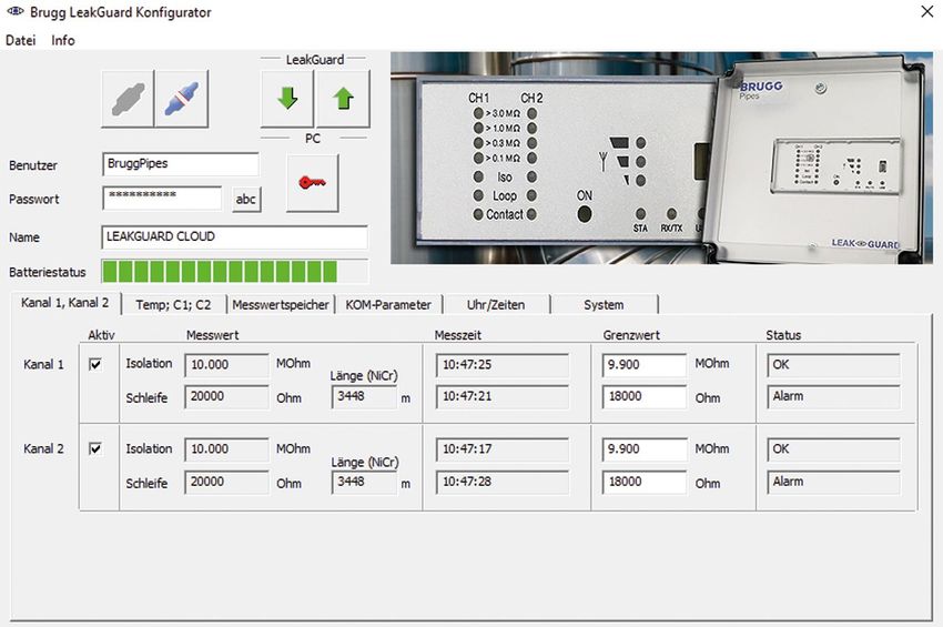
Page 15

“Channel 1, channel 2” tab

Each measurement channel to be monitored must be activated by checking the
corresponding checkbox in the first column.
If the LEAKGUARD CLOUD has already performed measurements, the last
measured values are displayed in the “Measured value” column with the corre-
sponding time stamp in the “Measuring time” column.
For NiCr measurements, the length of the measuring section is displayed.
The displayed value is not relevant for Cu measurements.
The limit values are can be freely edited.
Insulation: Alarm signal when exceeding 0 .. 10 MΩ,
Factory setting 0,5 MΩ. Decimal commas must be entered as full stops!
Loop: Alarm signal when exceeding 0 .. 19.99 kΩ,
Factory setting 12 kΩ. Decimal commas must be entered as full stops!
Page 16

“Temp., C1, C2” tab

Temperature
Temperature monitoring is activated in the delivery state.
It can be deactivated by clicking the corresponding checkbox in the first column.
If temperature monitoring is activated, the temperature value is also transmitted
with each message. The limit values are not evaluated and there is no alarm
when limit values are exceeded.
If the temperature is to be evaluated at the programmed wake-up time, the
"Evaluation" checkbox must be activated. An alarm is also triggered when
the limit value is exceeded.
The limit values can be freely edited from -20 °C to +140 °C.

Contacts
Each contact to be monitored must be activated by checking the correspond-
ing checkbox in the first column.
Status: Closed or open, set value = no alarm,
Factory setting: closed.
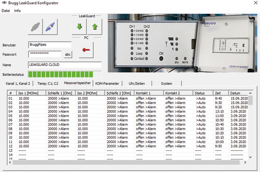
Page 17

Measured value memory tab

Displays a list of all results of the last 90 measurements with timestamp.
One line per measurement event.
The measured temperature values are not stored.

Test measurements without message dispatch are not considered.
Test measurements with message dispatch are entered with the status "Manu".
Page 18

COM parameters tab

The connection parameters for communication with the UMS server via the
mobile network are entered here.
It also provides information about the mobile connection.

APN = Access point name is the name of the gateway between the mobile net-
work and the public Internet.
The required APN can be selected from the “APN-Presets” pull-down menu.
In this case, the remaining required parameters are entered automatically.
It may be necessary to add APN -User and APN-Password.
Maximum number of characters: APN-Name:               64 characters
                              APN-User:               30 characters
                              APN-Password:           30 characters
Status
The system status of the mobile connection is displayed here.
SIM PIN number
The PIN number of the SIM card used must be entered here to ensure connec-
tion to the mobile network.
Signal level
The signal level of the last mobile connection is displayed here.
Operating mode
Here you can select from the pull-down menu which mobile connection or com-
bination should be used.
Page 19 Time/Date tab Wake-up time: Here you define the time at which the measuring cycle is to be started daily. Measurement interval: The LEAKGUARD CLOUD is designed for daily measure- ments. If shorter measuring intervals are required, they can be shortened to hourly or every 10 minutes using the radio knob. The shorter intervals should only be used tempo- rarily for testing purposes, as this reduces the battery life considerably. Send status message on: The LEAKGUARD CLOUD sends a status message weekly at wake-up time to document that it is active and simultaneously sends all entries from the history that have not yet been transmitted to the UMS server. The day of the week is freely selectable via the pull-down menu. If the "Daily" status is selected in the pull-down menu, a status message is sent every day at wake-up time. This reduces the operating time of the battery. Setting time and date: This data can be changed by clicking on the menu arrows on the right side of the input fields or entered using the keyboard. Press the “Set clock” button to transmit to the LEAKGUARD CLOUD. Alternatively, the system time of the used laptop/notebook can be adopted by clicking the “Set clock with system time” button . Caution: There is no automatic changeover between winter and summer time.
Page 20

System tab

Here the UMS server data is entered and the device-related data such as the
serial number, type and version number is displayed.
Error messages in the "System status" field can be acknowledged as read and
reset by pressing the       button.

If BRUGG server hosting is used, the following UMS server address must be
entered:
UMS server:         Ums.leakguard.ch (max. 64 characters)
Port specification: 2050 (field after “:”)
UMS work group:     Freely selectable name (max. 30 characters)
If a separate server   is used, the following must be entered:
UMS server:             IP address or name of the server (max. 64 characters)
Port specification:     According to the circumstances (field after ":")
UMS work group:         Freely selectable name (max. 30 characters)

To transmit the changes of the settings to the LEAKGUARD CLOUD, press the
     button.

This can be done on each settings page and after each change, or once after all
settings have been completed.
Caution: The transmission of the change of time and date is done exclusively
via the two       and                buttons.
Page 21 A test message should be sent to check if communication data, such as APN- Name, PIN, etc. was entered correctly. Press and hold the "ON" button on the LEAKGUARD CLOUD for 5 seconds (see page 10). If the UMS server does not receive a message from the LEAKGUARD CLOUD, the APN access data and the PIN number must be checked. To read out the saved data, click the button in the LGKonfigurator and switch to the "COM parameters" or "System" tab. Incorrect PIN entry / Unlocking via PUK If the wrong PIN number is accidentally entered, no alarm and status messages can be sent. If the SIM card does not accept the PIN number, this is indicated in the "Modem info" field of the LGKonfigurator: After the fourth transmission attempt with an incorrect PIN number, the SIM card automatically locks. This is displayed in the "Modem info" field of the LGKonfigurator:
Page 22

A blocked SIM card can be unlocked using the PUK number.
To unlock, enter the freely selectable 4-digit SIM PIN number in the "SIM PIN
number" field and the 8-digit PUK number specified by the mobile provider in
the "PUK" field and upload it to the LEAKGUARD CLOUD by pressing the
            button.

A test message is then automatically sent to the registered UMS server.
Then the new SIM number is set and the SIM card is unlocked again.
Page 23 To finish configuration, the button for separating the software and device must be pressed. The USB cable can then be disconnected from the device and computer and the "LGKonfigurator" program can be closed. Configuration is complete.
Page 24

Saving / Loading device configuration

The LGKonfigurator offers the option of saving device settings or loading saved
settings.
This function is not password protected.
Clicking the “File” menu item opens a pull-down menu with the following options:
Load data set          Imports device settings that were previously saved in
                       a data set (file format xxx.rmd) from a connected PC/
                       laptop, etc.
                       If the LGKonfigurator was not yet connected to the device,
                       it first reads the configuration of the device when connect-
                       ing. If another saved data set is to be used, it must then
                       be imported.
Page 25
Save data set Saves the current device configuration in a data set on
the connected PC/laptop, etc.
The device name is suggested as the file name.
However, the file name can be changed at will.
Note:
The changed data of the LGKonfigurator is only transmitted to the device when
the button is clicked.
Its configuration does not change before this happens!
Export history Stores the measured data from the measured value
memory in a CSV file on the connected PC/laptop etc.
The device name is suggested as the file name.
However, the file name can be changed at will.Page 26
End Closes the “LGKonfigurator” program.
Before exiting the program, the configuration must be
finished, see the following point.
To finish configuration, the button for separating the software and device
must be pressed.
The USB cable can then be disconnected from the device and computer and
the "LGKonfigurator" program can be closed.
The configuration is finished, the RMConfigurator can be closed.Page 27
Maintenance
Changing battery
CAUTION! Lithium battery!
Only use original battery 3.6 V / 19 Ah with holder and connection
cable. Never charge, reverse polarity of or short circuit a lithium
battery.
If necessary, observe shipping instructions for lithium batteries
(Class 9, UN3090 or UN 3091).
The LEAKGUARD CLOUD is equipped with
a 3.6 V lithium battery (A), which is mount-
ed at the factory but not yet connected.
A new battery has a lifetime of more than
5 years with daily measurements and
weekly status reports.
The housing of the LEAKGUARD CLOUD
must be opened to change a battery
(BRUGG order number 1089454).
To do so, unscrew the 4 screws on the
housing corners and lift the housing cover.
Loosen the “C” screws of the panel and
remove panel.
Disconnect the battery plug (B) and
remove the battery (A) together with the
holder from the top-hat rail.
Snap the holder with the new battery (A) onto the top-hat rail. Attach the reverse
polarity protected battery plug (B) of the new battery (BRUGG order number
1089454) to connection X6 (see page 6).
Reposition and tighten panel, then close and tighten housing cover.
Battery error message
A battery error message appears if the battery voltage of the LEAKGUARD
CLOUD falls below 3 V and should be replaced.
This message is always sent together with the weekly status message or
with an alarm or OK message.Page 28 Battery disposal • Do not dispose of empty or defective lithium batteries with normal household waste! • Observe the regulations of the Battery Directive. • Bring empty or defective lithium batteries to a battery collection point.
Page 29

UMS server
The messages transmitted to the UMS server are assigned to the correspond-
ing device and evaluated there.
All relevant data can be seen at a glance.
Page 30

Compliance statement for modem
RED Directive 2014/53/EU
The LEAKGUARD CLOUD uses the HL7692 modem from Sierra Wireless
Inc., which was integrated in accordance with the manufacturer's installation
instructions.
Sierra Wireless Inc certifies in a "Compliance statement" that the modem meets
the requirements of RED Directive 2014/53/EU (Radio Equipment Directive).
Page 31
EU Declaration of Conformity
BRUGG Rohrsystem AG
Industriestrasse 39         We declare in sole responsibility that the product
CH-5314 Kleindöttingen
Tel. +41 (0) 56 268 78 78
                             Brand:                  BRUGG Pipes
pipes@brugg.com
bruggpipes.com               Type:                   LEAKGUARD CLOUD

                            to which this declaration refers complies with the relevant basic
                            health and safety provisions of the following EU directives:

                             2014/30/EU              Electromagnetic Compatibility
                             2011/65/EU              RoHS-II
                             2014/53/EU              RED

                            The following standard(s) and/or technical specification(s)
                            were used for proper implementation of the safety and health
                            requirements specified in the EU Directives:

                             EN 61010-1              Safety requirements for electrical
                                                     equipment for measurement, con-
                                                     trol, and laboratory use – Part 1
                             EN 61326-1              Electrical equipment for measure-
                                                     ment, control and laboratory use -
                                                     EMC requirements (class B)

                            Kleindöttingen, 21/9/2020

                            Management

                            BA 076354.000/Rev. 00
You can also read