Optimal Soft Composites for Under-Actuated Soft Robots
←
→
Page content transcription
If your browser does not render page correctly, please read the page content below
Research Article
                                                                                                                                    www.advmattechnol.de

Optimal Soft Composites for Under-Actuated Soft Robots
Narasimha Boddeti, Tien Van Truong, Vincent S. Joseph, Thileepan Stalin, Theo Calais,
Shien Yang Lee, Martin L. Dunn, and Pablo Valdivia y Alvarado*

                                                                                                       functionality.[13,14] Soft robot bodies are
Material properties and composite structures play key roles in tailoring the                           most often underactuated composite struc-
performance of soft robots. Unfortunately, current design and fabrication                              tures that combine elastomers capable
approaches limit achievable complexity and functionality in these two                                  of large elastic deformations (strains as
categories and hinder soft robot performance. Here, an approach that                                   high as 1000%) with stiffening compo-
                                                                                                       nents used to constrain body strains under
allows design and direct fabrication of novel soft composite structures
                                                                                                       actuation,[15–18] or to bear computation
is presented. The process uses computational topology optimization to                                  and power hardware.[19] Soft robot per-
determine the required 3D composite structure of soft hyper-elastic bodies.                            formance is therefore highly sensitive to
The direct fabrication of the soft composite structures using an all-in-one                            material composition, material distribu-
fabrication workflow with resilient silicone polymers enables precise tailoring                        tions, and component geometries (e.g.,
                                                                                                       flexural rigidity distributions on bodies,
of mechanical properties. By applying this approach to the design and
                                                                                                       fingers, tentacles, wings, fins, etc.). Unfor-
fabrication of an underwater batoid-inspired soft robot, significant swimming                          tunately, prevailing fabrication approaches
performance improvements is demonstrated. An optimized composite                                       for soft robot bodies still rely primarily on
prototype displays 50% faster swimming speeds, 28% faster turning rates,                               manual casting methods with low fabrica-
and 55% smaller turning radii than un-optimized benchmark prototypes.                                  tion resolutions, limited material options,
                                                                                                       and multiple steps to manufacture indi-
                                                                                                       vidual components (see Figure S1 in Sup-
1. Introduction                                                                 porting Information Section S1). This standard approach does
                                                                                not allow the fabrication of composite structures with complex
The field of soft robotics is undergoing rapid advances thanks                  internal features and advanced geometries.
to studies on novel mechanisms for sensing,[1,2] actuation,[3–5]                   Recent advances made in additive manufacturing have dem-
locomotion,[6–8] grasping and manipulation,[9–11] as well as the                onstrated the processing of multiple materials in composite
development of new approaches for modeling and control.[12] In                  structures. Several groups have successfully fabricated functional
this new field, materials play a central role in performance and                robots actuated by hydraulics,[20] combustion,[6] and catalytic fuel
                                                                                decomposition.[21] One common approach is the use of inkjet-
Prof. N. Boddeti                                                                based 3D printers that allow multi-material fabrication at high
School of Mechanical and Materials Engineering                                  resolutions along with graded properties.[6,22,23] However, the
Washington State University
Sloan Hall Room 213, 405 NE Spokane Street, Pullman, WA 99164, USA              stringent fluid mechanical requirements of ink-jet printing pro-
Dr. T. V. Truong, S. Y. Lee, Prof. P. Valdivia y Alvarado                       hibits the use of high viscous or particulate-filled inks essential
Engineering Product Development (EPD)                                           to add functionalities (e.g., magnetic or electrical properties),[24]
Singapore University of Technology and Design                                   while the commercially available photopolymerizable acrylate-
8 Somapah Road, Singapore 487372, Singapore                                     based inks used in these processes suffer from low maximum
E-mail: pablov@sutd.edu.sg
                                                                                strains (100% strain before failure) and rapid ageing under
Dr. V. S. Joseph, T. Stalin, Dr. T. Calais, Prof. P. Valdivia y Alvarado
Digital Manufacturing and Design (DManD) Center
                                                                                humidity or UV exposure.[25,26] Extrusion-based technologies
Singapore University of Technology and Design                                   such as direct ink writing (DIW) accommodate a wider range
8 Somapah Road, Singapore 487372, Singapore                                     of materials with diverse properties.[14] In particular, embedded
Prof. M. L. Dunn                                                                3D printing (E3DP) is of interest for its compatibility with multi-
College of Engineering                                                          material fabrication. In this process, various material inks are
Design and Computing                                                            extruded into a fluid reservoir (also referred to as matrix), which
University of Colorado Denver
North Classroom, 1200 Larimer Street, Room 3034, Denver, CO 80204, USA          provides support to features that would otherwise deform under
      The ORCID identification number(s) for the author(s) of this article      the effects of gravity. First demonstrated to fabricate a biomi-
      can be found under https://doi.org/10.1002/admt.202100361.                metic microvascular network,[27] this process has been adapted
© 2021 The Authors. Advanced Materials Technologies published by                to fabricate soft sensors,[1] fluid-based actuation for soft robots,[21]
Wiley-VCH GmbH. This is an open access article under the terms of the           and perfusable tubular structures.[28,29] The materials used as res-
Creative Commons Attribution-NonCommercial-NoDerivs License,                    ervoirs rely on yield stress behavior leading to local fluidization
which permits use and distribution in any medium, provided the original         in response to shear loads from the translating extruder, allowing
work is properly cited, the use is non-commercial and no modifications
or adaptations are made.
                                                                                ink extrusion, while the bulk material behaves like a solid to
                                                                                support previously extruded features. To be successful, E3DP
DOI: 10.1002/admt.202100361                                                     requires exquisite control of rheological properties of both inks

Adv. Mater. Technol. 2021, 2100361         2100361 (1 of 12)                 © 2021 The Authors. Advanced Materials Technologies published by Wiley-VCH GmbH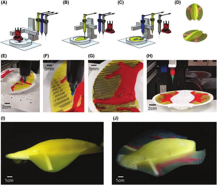
www.advancedsciencenews.com                                                                                                            www.advmattechnol.de

and matrix, but significantly widens the possibilities in terms of          2.2. Modeling the Fin Kinematics
design of composite structures.
   Appropriate computational design tools are needed to                     The robot dynamic performance is directly determined by the
fully exploit the freedom and flexibility afforded by these new             fin kinematics, which is influenced by both the fin material
multi-material fabrication processes. Approaches to design                  properties and fluid structure interactions for a given geometry.
and optimize geometries, actuation placement, and mate-                     Batoid fin kinematics are typically characterized by travelling
rial distributions can have an important impact on soft robot               waves (see Figure 1B),[45,46] which on a circular platform can be
performance and efficiency.[30–34] Topology optimization (TO)               approximated by:
is a well-developed design tool for structural applications.[35]
Its application to soft robot design has not been thoroughly                w (θ , r , t ) = H (θ ) J (r ) sin (κθ − ω t )                                 (1)
explored but steadily gaining traction.[36–41] When combined with
multi-material 3D printing, TO affords exquisite design freedom                Where w is the out-of-plane (z-axis) fin displacement, ω = 2πf
hitherto unavailable with traditional fabrication approaches.               is the flapping frequency in rad s−1 (f is the flapping frequency
However, TO-based design does not take fabrication processes                in Hz), H(θ) is the amplitude envelope of the fin oscillations
and their associated constraints into consideration. While some             along the azimuthal axis (green lines in Figure 1B), J(r) is the
recent efforts focusing on voxel-based 3D printing have made                amplitude envelope of the fin oscillations along the radial axis,
progress in this direction,[42,43] more work remains to be done.            and κ is the wave number that characterizes the wavelength λ
   In this work, we combine TO with an additive manufac-                    of fin oscillations (κ = 2π/λ). Equation (1) can be re-written as:
turing hub to design and fabricate complex soft composite
bodies with tailored properties, addressing limitations in                 w (θ , r , t ) = H (θ ) J (r ) ( sin (κθ ) cos (ω t ) − cos (κθ ) sin (ω t ))
                                                                                                                                                           (2)
design, materials, and process implementation. This approach               ∴ w (θ , r , t ) = a (θ , r ) cos (ω t ) + b (θ , r ) sin (ω t )
is applied to the fabrication of an underwater batoid-inspired
underactuated soft robot, as fin-based underwater locomotion                where the spatial response of the fin motions is assumed to
provides a great experimental tool to demonstrate the impact                be fully decoupled from the temporal response and the spa-
of kinematics on locomotion. Under-actuation keeps the design               tial component is split into in-phase, a(θ,r), and out-of-phase,
of the actuator simple at the expense of the ability to tailor the          b(θ,r), parts.
robot kinematics when using simple fin designs with isotropic                  It is challenging to efficiently capture these two compo-
materials.[44] Robots with composite anisotropic fins display               nents in a computational model using fluid structure interac-
locomotion performance not attainable by robots using simple                tions (FSI). Therefore, a cost-effective linear finite element
isotropic fins. Topology optimization is used to design such                (FE) model decoupling fluid and structural interactions and
composite soft fins with complex internal features, finetuning              built from experimental data was used in this work (see the
fin oscillatory behavior. The proposed approach automates two               Experimental Section). The fluidic forces were accounted for
key steps in the design and fabrication of soft robots: i) com-             using added mass and added damping models, widely used in
posite feature design using TO and ii) fabrication of complex               marine hydrodynamics,[47] with a series of simplifying assump-
composite features in one single fabrication hub. These steps               tions: i) only the z-direction components are non-zero, ii) both
enable structural customization and functionalization capa-                 are uniformly distributed over the fin, and iii) both depend
bilities not currently achievable with standard fabrication                 only on the effective wave number in the current context.
approaches, significantly contributing to the development of                By focusing on steady-state fin dynamics and ignoring tran-
the fabrication of soft robots with tailored capabilities.                  sients,[35] this simplified FE model was sufficient for deter-
                                                                            mining the in-phase and out-of-phase spatial responses (i.e.,
                                                                            a(θ,r) and b(θ,r) respectively) of the fin kinematics and was
2. Design and Modeling of a Soft Batoid Robot                               employed in the optimization of the fin material distribution
                                                                            described in this article. More details on the FE model are given
2.1. Soft Batoid Robot Design                                               in the Experimental Section.
                                                                               Earlier batoid studies identified the fin flapping wavelength
Batoids, with their large fins, provide a great biological example          λ (or equivalently fin wavenumber κ) as a key parameter to
of fin-based underwater locomotion where the changes in kin-                differentiate undulatory type swimming (small wavelengths)
ematics of the propulsor (fin) can have a striking impact on                specialized for low-speed swimming with reduced drag and
maneuverability and propulsion. Thus, a soft batoid-like robot              high maneuverability, from oscillatory swimming (longer
was chosen here to demonstrate how tailoring the fin composi-               wavelengths) which provides better lift performance, good for
tion could impact the kinematics and so the locomotion perfor-              steady cruising and higher thrust production but affording less
mance. The design developed for this study is similar to the one            maneuverability.[48] Finetuning the fin wavelength can therefore
reported in ref. [45] and is shown in Figure 1A. Briefly, the robot         enable a better compromise between high-speed swimming
is under-actuated: only one flexible flapper per soft fin, actuated         and good maneuverability.
by a servomotor, is used to excite fin oscillations and trigger loco-          Fabrication using single isotropic materials limits the ability
motion controlled by an on-board Arduino Uno microcontroller                to tailor fin kinematics, including fin wavelengths. With the
and powered by a rechargeable lithium-polymer cell. The robot               extensive freedom unlocked by E3DP and the fabrication hub
is neutrally buoyant, has a disk length (DL) of 180 mm, and is              detailed herein, designers can achieve unique fin kinematics
fully encapsulated using platinum catalyzed silicone polymers.              through finely tailored material distributions. Determination

Adv. Mater. Technol. 2021, 2100361     2100361 (2 of 12)                © 2021 The Authors. Advanced Materials Technologies published by Wiley-VCH GmbH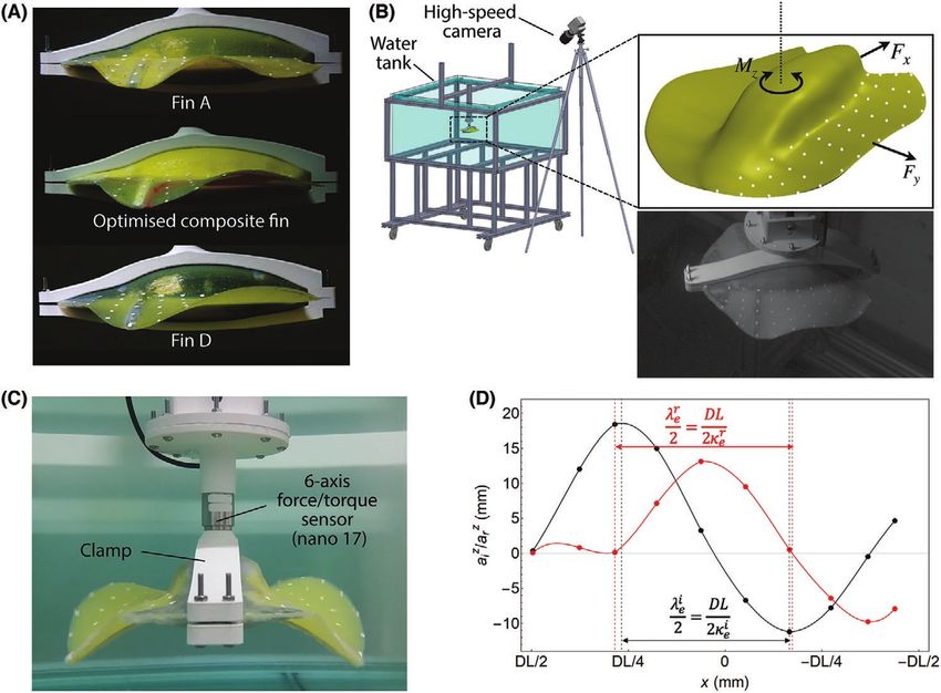
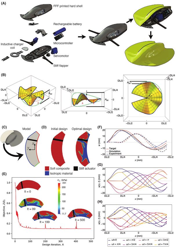
www.advancedsciencenews.com                                                                                                      www.advmattechnol.de

Figure 1. Soft batoid robot design and topology optimization. A) Robot components: two servo driven flappers excite large pectoral fin vibrations. An
internal microcontroller unit, rechargeable batteries, and an inductive charging unit enable full autonomy. The internal assembly is contained inside an
FFF printed shell and the entire body is encapsulated using a soft polymer. The robot has a disk length (DL) of 180 mm. Fin kinematics and dynamics
depend entirely on flapping actuation and fluid-structure interactions.[45] B) Batoid-like fin kinematics and relevant parameters: wavelength λ and peak
to peak flapping amplitude App. C) Large pectoral fin (light gray) model. The black fin region indicates the embedded flapper location, red edges are
fixed, blue and green edges represent the fin’s free boundary. D) Initial and optimal designs with different material regions identified and optimal
fiber orientations indicated via short black lines. E) Optimization objective z, normalized with respect to the initial error, versus iteration number.
F) Comparison of the in- (solid curves) and out-of-phase (dashed curves) deflections of optimal design obtained from simulations (black curves) and
experiments (blue curves) with target kinematics (red curves). G) Span-wise (i.e., blue edge in (C)) deflections of optimal fin design at different times
obtained from simulations, H) Span-wise fin deflections obtained from experiments.

Adv. Mater. Technol. 2021, 2100361         2100361 (3 of 12)              © 2021 The Authors. Advanced Materials Technologies published by Wiley-VCH GmbH
www.advancedsciencenews.com                                                                                                www.advmattechnol.de

of the material distribution (i.e., topology) that leads to             3. Results
a desired fin wavelength can be posed as a TO problem.
Topology optimization can then be used as a design tool to              3.1. Topology Optimization
tailor fin kinematics.
                                                                        To simplify the fabrication process, the optimization proce-
                                                                        dure was set up to output a fin design composed of only two
2.3. Topology Optimization of a Batoid Fin                              materials: i) a “stiff” material used as “matrix” (denoted Mate-
                                                                        rial D with a Young’s modulus E = 230.7 kPa); ii) a “soft” mate-
Topology optimization is a structural design method wherein             rial used as reinforcement (denoted Material A, with a Young’s
structural analysis is coupled with an optimization algorithm           modulus E = 11.74 kPa). Material A and D correspond to two
to reach an optimal arrangement of one or more materials.               of the four soft 3D-printable materials that were prepared for
This can be adapted to optimize material distributions within           this study (see Table 1 and Section S2 in the Supporting Infor-
any sub-region of the robot (e.g., fin) to achieve prescribed           mation). In the optimization procedure, both Em and θi were
objectives and constraints. Following the approach developed            set as design variables, respectively describing the macroscale
by Boddeti et al.,[43] a novel multiscale TO problem was setup          topology (i.e., distribution of materials) and microscale struc-
to finetune the kinematics of the soft batoid robot fin via the         ture (i.e., orientation of fibers), while the other parameters were
design of a short fiber-based composite structure, aiming to            fixed (Ef = 11.74 kPa, α = 10, θo = 0, and φ = 0.05). It should be
enhance locomotion performance in terms of forward velocity             highlighted that the “reinforcement” in this study is used as a
and yaw turning maneuvers over an isotropic fin (defined as             softener of the matrix.
benchmark). This approach enables optimization of both the                 The optimization objective, z, was mathematically expressed
macroscale material distribution and microscale architecture of         as the time-averaged squared Euclidean norm of the difference
the composites and can be summarized as follows. The fiber-             between the simulated fin kinematics and prescribed target
based composite microstructure is characterized by the fiber            kinematics integrated over the fin area:
volume fraction, φ, aspect ratio, α, in-plane and out of plane
fiber orientations, θi and θo, in addition to the Young’s moduli,
Em and Ef of the constituent matrix and fiber materials respec-                   (
                                                                        min z = ∫ ( a − a T ) + ( b − bT ) dA
                                                                                               2          2
                                                                                                              )
tively. In the optimization procedure, each of these composite                        s.t. 0 ≤ θ i ≤ π                                         (3)
parameters can be treated as a design variable. Given the con-                        E m1 ≤ E m ≤ E m2
stituent material properties (Em and Ef ) and microstructural
details (φ, α, θi, and θo), the composite material can be mod-             Here aT(x,y) and bT(x,y) are the targeted (i.e., based on the
eled as a homogenous transversely isotropic material with the           target fin wavelength) in- and out-of-phase responses, respec-
homogenized material properties evaluated analytically using            tively. The composite matrix modulus was chosen to vary
the Mori-Tanaka homogenization scheme.[49] This makes the               between Em1 = 11.74 kPa and Em2 = 230.7 kPa. This variation
optimization procedure efficient by avoiding the need for com-          was achieved by adapting the widely used SIMP (solid isotropic
putationally expensive FE meshes to resolve the mechanics               material with penalization) method:[35] the matrix modulus
at the smaller length scales (approximately fiber diameter).            was defined in terms of a fictitious density, ρ (0 ≤ ρ ≤ 1) such
Homogenization, however, requires an effective de-homogeni-             that: Em = Em1 + (Em2 – Em1) ρ3. A projection filter that maps
zation procedure to realize a manufacturable composite from             ρ to either 0 or 1 was used to minimize intermediate values
the homogenized composite description obtained from the                 for ρ.[43] This ensures an optimal design where Em essentially
optimization. This was achieved by reducing the de-homog-               takes either a value of Em1 when ρ = 0 or Em2 when ρ = 1. If
enization problem into a geometric problem of arranging cyl-            Em = Em1 = Ef = 11.74 kPa, the composite became homogenous
inders (i.e., fibers) in accordance to the optimization results         (matrix and fiber are the same material) and thus isotropic with
(see ref. [43] for more details).                                       modulus Em1. Thus, during optimization, the material distribu-
   Here, the TO problem was set up to synthesize a fin mate-            tion was essentially varied between: i) the soft isotropic material
rial composition that achieves a prescribed target fin kin-             (Material A, E = Em1 = 11.74 kPa) and ii) the soft composite made
ematics, wT(θ,r,t) (or equivalently wT(x,y,t) in the numerical          of a stiff matrix (Material D, Em = Em2 = 230.7 kPa) and soft
model where a Cartesian coordinate system was employed).                fibers (Material A, Ef = 11.74 kPa) with spatially varying orienta-
An intermediate wave number κ = 1.07, corresponding to                  tion, θi, set to vary between 0 and π. Solid shell finite elements
λeComp = 0.17 m, was chosen for the prescribed target kinematics,       were used in the FE model to discretize the fin geometry, thus
as it cannot be obtained with any isotropic material and can            allowing treatment of the fin as a laminated composite with the
improve the robot locomotion performance in terms of forward            ability to vary ρ and θi in each layer to be varied independently.
velocity and yaw turning maneuvers over isotropic benchmark             The number of layers were restricted to 2, an arbitrary choice,
fin designs. The fin geometry used in this study is shown in            in this study.
Figure 1C. The black region indicates the location of the flap-            Using a simplified data-driven FE model build from four
ping actuator that sets off the traveling waves along the fin.          isotropic fins (Material A to D, with increasing modulus (see
The red solid lines indicate fixed boundaries (the base of the          the Experimental Section for details)), the TO problem pro-
fins where the central body starts) and the blue lines mark the         ceeds at each iteration as follows. First, the FE model of the
fin azimuthal boundary along which the fin edge deflections             fin dynamics is solved, and the objective z is evaluated (see
(w(θ,r≈DL/2,t)) were plotted and evaluated.                             Equation (3)). This is followed by a gradient-based optimization

Adv. Mater. Technol. 2021, 2100361   2100361 (4 of 12)              © 2021 The Authors. Advanced Materials Technologies published by Wiley-VCH GmbH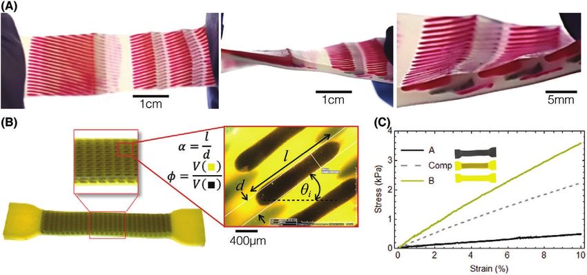
www.advancedsciencenews.com                                                                                                                 www.advmattechnol.de

Table 1. Available ink and matrix materials. Relevant material properties of the various materials synthesized for matrix and composite pattern
fabrication.

Material Id       Assigned name                  Examples                  Density [g cc−1]   Young’s Modulusa)   Ultimate Tensile   Elongation at   Toughnessb)
                                                                                                    [kPa]         Strengthb) [kPa]    breakb) [%]      [kJ m−3]
A                     Soft ink          Fin A, Figure 2A: red fiber-like        1.03                11.7                136              1906            1183
                                      features, Figure 2B and Figure 3:
                                         black fiber-like features and
                                                 red reservoir
B                 Softer reservoir          Fin B (see Supporting               1.05                52.8                343              1340           1951
                                       Information), Figure 2A: black
                                        fiber-like features, Figure 2B:
                                                yellow reservoir.
C                  EcoFlex-0030            Fin C (see Supporting                1.07                86.9                876              1267           4443
                                                Information)
D             SORTA-Clear reservoir   Fin D, Figure 3: yellow reservoir         1.08               230.7               1273              903            4853

a)Young’s  modulus of the samples (samples A to D) was measured by uniaxial compression tests with cylindrical specimens (35 mm height and 40 mm diameter). The
strain rate was 1% s−1, sampling rate 50 Hz up to 10% strain. The average values were obtained using a minimum of three samples; b)A modified dogbone, adapted from
ASTM 412C (test section: 11 mm long, 2 mm wide, and 3 mm thick) was used to measure the ultimate tensile strength (UTS), toughness and elongation at break values
(samples A to D). The strain rate was 1% s−1, sampling rate 10 Hz up to specimen breaking point. The average values were obtained using a minimum of three samples.

step where the GCMMA (Globally Convergent Method of                                      3.2. Fabrication of a Soft Batoid Robot
Moving Asymptotes) algorithm was used.[50] During this step,
the gradient of the objective with respect to the design vari-                           Three types of fins were fabricated to evaluate experimentally
ables, θi and Em, are calculated via the adjoint method.[35] The                         the impact of the fin material properties on robot locomotion
gradients are then used by GCMMA to update the design vari-                              performance: i) a soft isotropic fin denoted Fin A (Material A);
ables and thus the design. Iterations were stopped if the relative                       ii) a stiff isotropic fin denoted Fin D (Material D); iii) a com-
change in the objective function between consecutive iterations                          posite fin combining Materials A and D with a design deter-
is below a prescribed threshold.                                                         mined by TO.
   The TO procedure starts with an initial design where all the                              The material compositions used for the fabrication of bench-
ρ and θi were uniformly initialized to arbitrarily chosen values                         mark and composite fins are detailed in Table S1 in the Sup-
of 1 and π/8, respectively. The fin design, at this stage, consists                      porting Information (Section S2, Supporting Information).
of just the soft composite material with a uniform fiber orienta-                        Briefly, Material A is composed of Ecoflex 00–30 (Smooth-On)
tion of π/8 with respect to the x-axis. The optimal composite                            softened using Slacker (50 wt%) and thickened with THI-VEX,
design, shown in Figure 1D (right), is a complex distribution of                         while Material D is composed of SORTA-Clear (Smooth-On)
isotropic Material A and the soft composite consisting of Mate-                          with 12.5 wt% of Slacker. The fabrication process of the com-
rial A fibers embedded in Material D with varying orientations.                          posite fin requires the embedding of fluid features within a
The variation of ρ and θi across the two layers, as obtained, are                        liquid matrix, which demands a careful balance of fluid forces.
nearly identical, thus only the top layer is shown in Figure 1.                          Thus, the rheological properties of the pre-cured materials,
The history of the optimization objective z normalized to the                            herein called inks, were characterized and results are detailed
initial error z0 with snapshots of the intermediate designs at                           in Section S3 (Supporting Information). All inks exhibit shear-
select iterations is shown in Figure 1E. A converged result was                          thinning behavior (i.e., a decrease of apparent viscosity of sev-
achieved within the first 100 iterations after which the optimi-                         eral orders of magnitude, from ≈1 kPa s to ≈1 Pa s, with the
zation process exclusively works to remove intermediate values                           increase of shear rate from 0.01 to ≈100 s−1). This property ena-
(see Movie S1, Supporting Information). Figure 1F compares                               bles both extrusion (low viscosity under high shear-stress) and
the in- and out of phase components of the azimuthal boundary                            shape retention once extruded (higher viscosity at low shear
deflections of the target kinematics and the optimal design kin-                         rate), either in air (for DIW) or while embedding in fluid reser-
ematics respectively (azimuthal boundary deflections are out-                            voirs (for E3DP). In addition, all inks possess yield stress fluid
of-plane fin displacements along the blue boundary shown in                              behavior, at low stresses the storage modulus exhibits a plateau
Figure 1C) at various times during the flapping period. Finally,                         at ≈1 kPa and ≈10 Pa for Materials A and D respectively and
Figure 1G,H respectively show the fin kinematics (boundary                               is higher than the loss modulus, which results in a solid-like
deflections) predicted by FE simulations and those character-                            behavior of the ink suitable to hold embedded features. Beyond
ized experimentally. A good agreement can be observed in both                            the yield stress (≈100 Pa for both inks), the storage modulus
azimuthal boundary deflections and fin kinematics between the                            decreases below the loss modulus, thus exhibiting a liquid-like
target, the model, and the experimental results. However, small                          behavior suitable for extrusion. Such yield stress fluid behavior
errors can be seen at the end of the flapping period. These are                          allowed crevasses left in the matrix by the ink dispenser move-
likely due to the assumptions made to build the computational                            ments to spontaneously close under hydrostatic pressure over
cost-effective FE model, even though the flapping behavior                               the crevasse height.[1] In case of higher yield stresses, a thin
could be correctly captured globally.                                                    layer of filler fluid, a low viscosity variant of the matrix material,

Adv. Mater. Technol. 2021, 2100361             2100361 (5 of 12)                    © 2021 The Authors. Advanced Materials Technologies published by Wiley-VCH GmbH
www.advancedsciencenews.com www.advmattechnol.de Figure 2. Soft composites. A) E3DP of soft fiber-like features within a stiff matrix to tune mechanical properties: arrays of short fiber-like features (material 1) embedded within a reservoir (material 2) help tailor tensile properties of the composite structure. B) Test sample of a soft composite, bulk modulus is tailored by the choice of fiber volume fraction, φ, fiber aspect ratio, α, and in-plane and out-of-plane fiber orientations, θi and θo (not shown); l and d are the embedded fiber length and diameter respectively. C) Stress–strain curves for tensile tests on the composite sample and its individual components. can be deposited on top of the matrix. Furthermore, the specific (Material D, in yellow), the soft fiber-like features (Material A, in gravities of inks and matrix were balanced to prevent floating black) are embedded in the stiff matrix (see Movie S2, Supporting or sinking of deposited features (see Table 1), even though the Information). The stiff matrix was purposely made more flowy to viscoelastic nature of the matrix provides some leeway in terms fill the mold evenly and obtain smooth surfaces. Figure 3I shows of ink buoyancy as viscous forces from the matrix can resist the benchmark robot with isotropic stiff Fins D, and Figure 3J buoyancy forces.[51] shows the finished soft batoid robot with composite fins (corre- Cured materials were characterized by compression and sponding to the final fin design obtained at iteration 500 from uniaxial tension tests, results are summarized in Table 1 and TO). More details on the fabrication hub and the G-code genera- details can be found in Section S3 (Supporting Information). tion are provided in Section S4 (Supporting Information). Due to the addition of Slacker in Ecoflex, Material A displays an It should be highlighted that the composite soft body extremely low Young’s modulus (≈11 kPa) and high elongation exhibits 3D features as small as 400 microns, which are not at break (1900%). In contrast, Material D is much stiffer with a achievable through a conventional cast-and-assemble workflow Young modulus of 230 kPa and an elongation at break of 900%. (such as the one shown in Figure S1, Supporting Information). Figure 2A displays examples demonstrating the successful In addition, the platinum-cured silicone elastomers used in this embedding of short fiber-like features, within elastomeric example display more stable properties in harsh environmental matrices made of silicone-based materials (other examples of conditions (e.g., stable in temperatures ranging from −50 up to complex patterns are shown in Section S4, Supporting Informa- 200 °C), are immune to UV exposure and corrosion, and are tion). As shown in Figure 2B, soft fiber-like features (Material A) more resistant to biofouling than their commercial UV curable could be successfully embed within a different matrix (Material elastomer counterparts.[52] B) in a tensile-test specimen. In this example, a volume fraction φ = 0.05, aspect ratio α = 10, and a varying in-plane fiber orienta- tion θi, were implemented, resulting in the successful softening 3.3. Characterization of Soft Batoid Robot Locomotion of the stiff matrix, as seen in the stress versus strain curves (Figure 2C) compared with benchmark materials. Three robot configurations were studied to evaluate the impact Figure 3A–D shows the composite fin fabrication steps using of fin composition on robot locomotion performance: i) static a single fabrication hub for soft robots which minimizes the experiments with clamped prototypes were used to characterize amount of pre- and post-processing that is otherwise required fin kinematics, thrust forces, lateral forces, and yaw moments with traditional manufacturing methods. First, a mold for the produced by individual fins; ii) free swimming experiments robot body is fabricated using fused filament fabrication (FFF) were used to characterize robot displacements, velocities, (Figure 3A). Internal components (shells, flapper, batteries, etc., and accelerations while actuating both fins in phase; and iii) see Figure 1A) are positioned inside the mold before deposition free yaw turning experiments were used to characterize robot by DIW of the reservoir material (Figure 3B) in the fin regions. angular velocities and turning radii while actuating a single Internal features designed by TO are finally embedded via E3DP fin. The three prototypes used in the experiments are shown within the fin matrix (Figure 3C), resulting in a fully 3D-printed in Figure 4A, while the experimental setup design is shown soft composite robot (Figure 3D). Figure 3E through Figure 3H in Figure 4B. For static experiments, prototypes were clamped show details of the actual fin printing process: after DIW of the and immersed inside a water tank, white ink markers previ- isotropic soft matrix (Material A, in red) and the stiff matrix ously screen printed along their fin top surfaces were used to Adv. Mater. Technol. 2021, 2100361 2100361 (6 of 12) © 2021 The Authors. Advanced Materials Technologies published by Wiley-VCH GmbH
www.advancedsciencenews.com                                                                                                       www.advmattechnol.de

Figure 3. Fabrication of a soft batoid-like robot. A) A mold for the robot body is fabricated using FFF. B) Internal components (e.g., actuators, sensors,
batteries, etc.) are positioned inside the mold and a dispenser deposits body matrix material inside the mold. C) A precision dispenser is used to
embed elastomer inks using the identified optimal patterns. D) Various ink print features with isotropic material properties are embedded in isotropic
matrix materials to achieve composites with anisotropic material distributions. E) Fin printing: deposition of fin reservoirs via DIW. F) Fin printing:
E3DP of composite fiber features. G) Composite fin detail. H) Finished soft batoid robot composite fins. I) Soft Batoid robot with initial fin design,
It = 0, (isotropic hard fins). J) Soft Batoid robot with final fin design, It = 500, (optimized composite fins).

reconstruct fin 3D kinematics captured by a high-speed camera.                 the Supporting Information (see Movies S3 and S4, Supporting
A six-axis load cell was used to measure the instantaneous forces              Information). Results are summarized in Figure 5.
and torques generated by actuating a single fin (see Figure 4C).                  All prototypes were controlled using the same flapping fre-
For free swimming and turning experiments, prototypes were                     quency, f = 1.8 Hz, and peak-to-peak flapping amplitude App = 0.2
placed inside the water tank far away from its walls and straight              DL (where DL is the prototype disk length). This frequency was
swimming (both fins actuated in phase) or turning (only a single               chosen due to the specifications of the servomotors and the
fin is actuated) pre-programmed behaviors were wirelessly acti-                water tank size that prevent excessively fast swimming speed
vated. Free motions were tracked using a high-speed camera.                    (see Section S5 in the Supporting Information for details). The
Figure 4D shows the definition of the effective wavelength,                    three prototypes display different wavelengths and azimuthal
λe, of a fin motion based on the in-phase, aiz (black curve) and               amplitude envelopes. The isotropic soft fin, Fin A, displays a
out-of-phase, arz (red curve) responses obtained from the experi-              short effective wavelength (λeA = 0.13 m = 0.72 DL), the isotropic
ments. The vertical lines are used to define the half-wavelength               stiff fin, Fin D, displays a longer effective wavelength (λeD = 0.22
and thus the effective wavenumber κ e = (κ ei + κ er ) / 2. More               m = 1.22 DL), while the optimized composite fin displays an
details on the experimental setup are provided in Section S5 in                intermediate effective wavelength (λeComp = 0.17 m = 0.94 DL).

Adv. Mater. Technol. 2021, 2100361         2100361 (7 of 12)               © 2021 The Authors. Advanced Materials Technologies published by Wiley-VCH GmbH
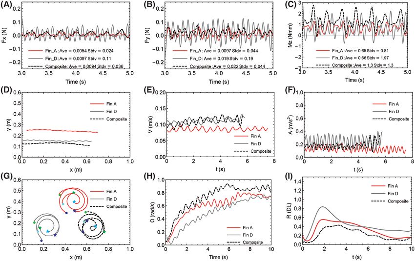
www.advancedsciencenews.com                                                                                                                    www.advmattechnol.de

Figure 4. Experimental setup for soft robot performance characterization. A) Side view snapshots of the three fins analyzed for this study (Fin A, Fin
D, and composite fin) at the end of a downstroke. B) 120 cm long, 120 cm wide, and 70 cm deep tempered glass water tank supported above ground
by an aluminum frame. The frame and the tank glass panels facilitate imaging of submerged prototypes from various angles. Prototypes can perform
free swimming maneuvers inside the tank, or they can be clamped to a load cell and fixed inside the tank for static force measurements. Side images
show details of the markers placed in the fin surfaces used for 3D reconstruction of fin kinematics. C) Detail of the force and torque measurement
experimental setup. Prototypes are mounted to a 6-axis load cell (Nano17, ATI Industrial Automation Inc., Apex, NC, USA) and actuated. For force
measurements only one fin was actuated, and Fx, Fy, and Mz were recorded. D) Plot showing the definition of the effective wavelength, λe of a fin
motion based on the in-phase, aiz (black curve) and out-of-phase, arz (red curve) responses obtained from experiments. The vertical lines are used to
define the half-wavelength and thus the effective wavenumber κ e = (κ ei + κ er ) / 2 and the effective wavelength λ e = ( λ ei + λ er ) / 2 = DL(1/ κ ei + 1/ κ er )/ 2,
with DL = 180 mm being the robot disk length.

   Figure 5A–C shows the instantaneous axial (thrust), Fx, and                        were the same as the ones used for static force and torque
lateral forces, Fy, as well as the instantaneous yaw moments,                         measurements and both fins of a prototype were actuated in
Mz, produced by a single fin for each prototype while it was                          phase. Unsurprisingly, the robot with soft fins (exhibiting
held static (see illustration in Figure 4A). Lift forces, Fz, roll, Mx,               lowest average thrust forces) displays the smaller average for-
and pitch, My, moments are not shown as they don’t contribute                         ward swimming speed (VA = 0.08 m s−1) while the robots with
significantly to forward motions or yaw turns. Average values as                      hard and composite fins display faster forward swimming
well as standard deviations are indicated in each graph (a min-                       speeds (VD = 0.11 m s−1 and VComp = 0.12 m s−1, see Movie S5
imum of 3 experiments were used to calculate these values).                           in the Supporting Information), in accordance with the larger
The isotropic soft fin produces the lowest average thrust                             average thrust forces previously determined. The robot with
and side force (FxA = 0.005 N, and FyA = 0.01 N) as well as the                       harder fins displays the largest variations in acceleration, most
lowest average turning moment (M zA = 0.65 N mm) with small                           likely due to the high variability (large standard deviation
standard deviations. The isotropic hard fin produces larger                           values) in thrust forces.
average thrust and side forces (FxD = 0.01 N, and FyD = 0.02 N)                          Figure 5G–I shows the instantaneous turning maneuvers,
and slightly larger average turning moment (M zD = 0.66 N mm)                         angular velocities, and turning radii of robots using the three fin
with much larger standard deviations. The optimized composite                         types during free turning experiments (a minimum of 3 experi-
fin produces average thrust and side forces (FxComp = 0.009 N,                        ments were used to calculate these values). Control parameters
and FyComp = 0.022 N) comparable to those of the hard fin, along                      were the same as the ones used for static force and torque
with the largest average turning moment (M zComp = 1.3 N mm)                          measurements but only one fin was actuated. While the robot
with small standard deviations similar to the values for the                          with soft fins displays smaller static side forces than the robot
soft fin.                                                                             with harder fins and almost identical average yaw moments
   Figure 5D–F shows the instantaneous displacements, veloci-                         (static), it outperforms the robot with hard fins in achieving
ties and accelerations of robots using the three fin types during                     slightly larger steady state angular velocities (ΩA = 0.8 rad s−1
free forward swimming experiments (a minimum of 3 experi-                             and ΩD = 0.7 rad s−1) and smaller steady state turning radii
ments were used to calculate these values). Control parameters                        (RA = 0.2 DL and RD = 0.4 DL). The larger turning radii

Adv. Mater. Technol. 2021, 2100361             2100361 (8 of 12)                  © 2021 The Authors. Advanced Materials Technologies published by Wiley-VCH GmbH
www.advancedsciencenews.com                                                                                                     www.advmattechnol.de

Figure 5. Soft batoid robot performance. Characterization of robots with isotropic fins A and D and optimal composite fins actuated with a flapping
frequency f = 1.8 Hz, and flapping amplitude App = 0.2 DL. A–C) Instantaneous thrust (x-axis) forces, instantaneous side (y-axis) forces, and instanta-
neous yaw moments (moments about the z-axis), all produced by a single fin (average and standard deviation values given in legend) of prototypes
clamped inside testing tank. D–F) Prototype displacements, instantaneous forward velocities, and instantaneous forward accelerations during free
swimming (both fins actuated in phase). G–I) Free yaw turning of soft batoid robots (single fin actuation): (G) Instantaneous positions of robot’s tip
(green markers), center (cyan markers), and end (blue markers) where circle markers denote initial positions and star markers denote final positions
after 10 s, H) instantaneous robot angular velocities, and I) instantaneous robot turning radii.

exhibited by the prototype using hard fins could be attributed to            4. Conclusions and Outlook
its larger thrust and side forces: while being beneficial for linear
motions, such attributes hinder the robot’s ability to perform               The integrated fabrication workflow presented in this study
sharp yaw turns. Ideally, a maneuverable robot should display                allows the realization of optimized material property distribu-
both small turning radii and large angular velocities. The robot             tions with less manual intervention compared to conventional
with composite fins benefits from these properties and outper-               soft robot fabrication methods. Further improvements could
forms both benchmark robots in steady state angular velocities               be achieved by incorporating automated material mixing pro-
(ΩComp = 0.9 rad s−1), and turning radii (RComp = 0.18 DL), see              cesses into the fabrication hub, thus eliminating remaining
Movies S6 and S7 (Supporting Information).                                   manual steps such as tool changes and material refills. Fur-
   The robot with optimized soft composite fins displays the                 ther work is also required to automate G-code generation for
largest average forward swimming speed (VComp = 0.12 m s−1),                 E3DP toolpaths with wireframe or vector-like printing moves
50% faster than the swimming speed produced by the soft fin                  (with directionality) in a more integrated manner (see the
and slightly higher than the swimming speed produced by the                  Experimental Section). A remaining obstacle to widespread
harder fin, with smallest variations in acceleration. The robot              adoption of new fabrication technologies lies in the availability
with optimized composite fins also achieved the fastest turning              of easy-to-use software tools to translate CAD data into tool
rate (ΩComp = 0.9 rad s−1) roughly 30% higher than the isotropic             paths and machine control programs. This problem is particu-
fins, and smallest turning radius (RComp = 0.18 DL) out of all               larly salient for E3DP. Finally, while features as small as 400
the three prototypes tested (less than half of the turning radius            microns could be obtained, improving the resolution of the
produced by the rigid fin). All these performance traits are                 extrusion-based printers to 100 microns and below could fur-
unachievable by a prototype with single isotropic material com-              ther improve the fiber density and thus the tailoring of the
position and demonstrate the potential of tailoring soft robot               final fin dynamics. With such enhancements, full automation
performance assisted by TO computational tools.                              could be obtained, thus improving repeatability and enabling

Adv. Mater. Technol. 2021, 2100361        2100361 (9 of 12)              © 2021 The Authors. Advanced Materials Technologies published by Wiley-VCH GmbH
www.advancedsciencenews.com                                                                                                                       www.advmattechnol.de

precise reconfigurations or modifications without large vari-                        Uniaxial compression tests for individual materials were performed at
ability on the results in prototype performance, required before                 ambient temperature using an MTS universal tensile machine mounted
commercialization of any device. As various soft robotic devices                 with a 100 N load cell, at a strain rate of 1% s−1, sampling rate of 50 Hz
                                                                                 up to 10% strain. Cylinder-shaped specimens with a 40 mm diameter
gain acceptance in industrial and more established applica-                      and 35 mm height were used. A minimum of 3 specimens were tested
tions, an automated or single fabrication hub approach could                     for each material. Compressions tests were found to be more reliable for
be upscaled in an industrial level to reduce costs.[53]                          materials with low moduli.
    To simplify the simulation work, linearized fin dynamics and                     Uniaxial tensile tests for individual materials and the fabricated soft
decoupled influence of the surrounding fluid dynamics were                       composites were performed at ambient temperature using an MTS
assumed. These assumptions enhanced the computational effi-                      universal testing machine mounted with a 100 N load cell, at a strain rate
                                                                                 of 1% s−1, sampling rate of 50 Hz up to 10% strain. For the elongation at
ciency of the optimization process while capturing the essential
                                                                                 break and tensile strength measurements the strain rates used were 1% s−1
experimental details qualitatively, demonstrating how a design-                  with a sampling rate of 50 Hz. A modified ASTM 412C standard dogbone
based workflow could be adapted for soft robot fabrication.                      (scale 1/3), 11 mm long, 2 mm wide, and 3 mm thick was used to measure
    Overall, the design and fabrication approaches presented                     modulus, ultimate tensile strength, and elongations at break. Dogbone-
in this study complement each other in a novel way to pro-                       shaped specimens large enough to accommodate composite features
vide a higher degree of customization and functionality in                       were also fabricated. The sample geometry used in these tests has a gauge
                                                                                 section that is 137.5 mm long, 25 mm wide, and 7 mm thick. Specimens
silicone based soft robot prototypes. Our computational design
                                                                                 were prepared by depositing the uncured material into the closed mold
approach enables optimization of a robot body material prop-                     using a pressure-based injection molding technique. For composite
erty distribution to yield desired body kinematics at a new level                samples, features of secondary inks were embedded within the sample in
of complexity. The required material distributions are trans-                    predefined patterns via E3DP. All the samples were cured at 23 °C for 16 h.
lated into equivalent soft composite structures and the resulting                After curing of the dogbone specimens, strain-limiting pads were glued to
tailored robot kinematics enable performance not achievable                      both sides of the grip sections covering each specimen except for the gauge
by isotropic materials. The significant improvement of both                      sections. Results are reported in Section S3 (Supporting Information).
                                                                                     Process Fabrication and Automation: The integrated fabrication
maneuverability and swimming speed of an under-actuated                          workflow described in this study was conducted on a modified
soft batoid-like robot strongly demonstrate the impact of this                   commercially available 3D printer (System 30M, Hyrel Inc.), which
dual approach to design and manufacture tailored soft robots.                    provided a multi-purpose 3-axis motion control, and a print head bay
Future work should include assessing the applicability of the                    that can hold up to four deposition tools (Figure S3A, Supporting
proposed approach for conditions where the robot is moving                       Information). Fused filament fusion operations used for molds printing
under currents or other perturbation sources.                                    were carried out using a manufacturer-supplied tool head (MK1-250,
                                                                                 Hyrel Inc), while fluid dispensing operations were carried out using a
                                                                                 pneumatic fluid dispensing system (Ultimus V, Nordson EFD) with
                                                                                 actuated disposable Luer-tipped syringes attached to the 3D printer
                                                                                 using a custom-made adapter.
5. Experimental Section                                                              G-code was automatically generated from CAD data using a
    Materials: Ecoflex 00–30, SORTA-Clear 12, THI-VEX, Slacker, SLO-JO,          customized version of the open-source Slic3r package. Due to the
and pigments (Silc Pig) were purchased from Smooth-On. The soft ink              complexity of the composite design and the large number of directional
and elastomeric reservoirs were synthesized by mixing Ecoflex 00–30              printing moves, substantial modifications of the core Slic3r package were
with appropriate amounts of SLO-JO, THI-VEX, Slacker and pigments                made to: i) generate toolpaths requiring wireframe or vector-like print
using a Planetary Centrifugal Mixer (ARE-310, Thinky Corp.; Tokyo,               moves, ii) automate 3D offsets when changing tool suitable for integrated
Japan) in a 200 mL plastic container using a custom adaptor. The ratios          FFF-E3DP workflows, and iii) integrate hardware-specific modifications
of each constituent are listed in Table S1 (Supporting Information).             to convert FFF commands to pneumatic pressure control dialect. These
    Each batch starts with premixing Ecoflex 00–30 part B with SLO-JO            modifications are discussed in Section S4 (Supporting Information).
first, followed by mixing Ecoflex 00–30 part A, THI-VEX, Slacker and                 Modeling Batoid-Like Fin Dynamics: To model the dynamics of the
pigments using a Thinky mixer for 2 min at 2000 rotations per minute             batoid soft robot, a simplified, data-driven linear finite element (FE)
(rpm). After mixing, the inks were de-foamed in the Thinky mixer for             model that decouples fluid and structural interactions was conceived.
2 min at 2200 rpm. THI-VEX and Slacker were added as a rheological               The experimental data needed for the FE model was obtained from four
modifier and silicone softener respectively, while SLO-JO was used to            isotropic fins with same geometries but different materials (Material A
extend pot-life and maximize printing time. For the stiffer reservoirs,          to D, with increasing stiffness). This data was used to relate added mass
SORTA-Clear 12 was used instead of Ecoflex 00–30.                                and added damping with the effective wave number, κ. As mentioned
    Rheology Characterization: The rheological properties of the inks were       in Results, the FE model was further simplified as the temporal
characterized using a controlled stress rheometer (Discovery HR-2                response could then be decoupled from the spatial response. Thus,
Hybrid rheometer, TA Instruments). A 40 mm parallel plate geometry               the out-of-plane fin deflections, w(x,y,t) could be effectively represented
with 200 µm gap was used for soft inks, reservoirs, and filler fluids.           by (assuming the forcing function is of the form facos(ωt) where
Rheological measurements of the inks were obtained within 20 min of              fa = actuation force magnitude):
their preparation. Viscometry measurements were carried out over shear
rates ranging from 0.01 to 4000 s−1, while oscillatory measurements              w ( x , y,t ) = a ( x , y ) cos (ω t ) + b ( x , y ) sin(ω t )                    (4)
were carried out at a frequency of 1 Hz within the stress range of
0.1 to 2000 Pa. All rheological measurements were carried out at 25 °C              Here, x and y are the spatial coordinates, t is the time, a and b are
under closed-loop temperature control. Detailed results are reported in          unknowns to be determined via FE analysis and represent the in-phase
Section S3 (Supporting Information).                                             and out-of-phase spatial response of the fin kinematics respectively.
    Mechanical Characterization: The stress strain behavior of the               More information on how the fin was modelled in steady-state dynamics
hyperplastic materials used for fabrication is highly non-linear and             and on the experimental calibration of the FE model are provided in
dependent on the strain rates used during tests. Von Mises Strain                Sections S6 and S7 (Supporting Information), respectively. Additional
averaged over the fin region from the FE simulations (≈1% s−1) was used          information on how the TO problem tackled the target kinematics is
to determine the strain rate for the tests.                                      available in Section S8 (Supporting Information).

Adv. Mater. Technol. 2021, 2100361        2100361 (10 of 12)                 © 2021 The Authors. Advanced Materials Technologies published by Wiley-VCH GmbH
www.advancedsciencenews.com www.advmattechnol.de
Supporting Information [8] E. W. Hawkes, L. H. Blumenschein, J. D. Greer, A. M. Okamura, Sci.
Rob. 2017, 2, eaan3028.
Supporting Information is available from the Wiley Online Library or [9] H. Zhao, K. O’Brien, S. Li, R. F. Shepherd, Sci. Rob. 2016, 1,
from the author. eaai7529.
[10] K. C. Galloway, K. P. Becker, B. Phillips, J. Kirby, S. Licht,
D. Tchernov, R. J. Wood, D. F. Gruber, Soft Rob. 2016, 3, 23.
[11] V. Subramaniam, S. Jain, J. Agarwal, P. Valdivia y Alvarado,
Acknowledgements Int. J. Robotics Research 2020, 1, 027836492091891.
Funding: This research project is supported by A*STAR under its [12] D. Rus, M. T. Tolley, Nature 2015, 521, 467.
Science and Engineering Research Council (SERC) Award 1822500053, [13] T. Calais, P. Valdivia y Alvarado, Multifunct. Mater. 2019, 2, 042001.
and by SUTD’s Digital Manufacturing and Design (DManD) Centre and [14] V. S. Joseph, T. Calais, T. Stalin, S. Jain, N. K. Thanigaivel, N. D. Sanandiya,
SUTD’s International Design Centre (IDC) under grants RGDM1620401, P. Valdivia y Alvarado, Appl. Mater. Today 2021, 22, 100979.
RGMD1620501, IDG31600101. M.L.D acknowledges support from the [15] J. Bishop-Moser, S. Kota, IEEE Trans. Rob. 2015, 31, 536.
AFOSR (19RT0543). [16] T. Stalin, N. K. Thanigaivel, V. S. Joseph, P. V. Alvarado, in 2019 2nd
IEEE Int. Conf. on Soft Robotics (RoboSoft), IEEE, Piscataway, NJ
2019, pp. 762–767.
[17] S. Y. Kim, R. Baines, J. Booth, N. Vasios, K. Bertoldi,
Conflict of Interest R. Kramer-Bottiglio, Nat. Commun. 2019, 10, 3464.
The authors declare no conflict of interest. [18] A. Chatterjee, N. R. Chahare, P. Kondaiah, N. Gundiah, Soft Rob.
2020.
[19] S. Jain, T. Stalin, E. Kanhere, P. V. y Alvarado, IEEE Rob. Autom. Lett.
2020, 5, 3907.
Author Contributions [20] R. MacCurdy, R. Katzschmann, Y. Kim, D. Rus, in 2016 IEEE Int.
N.B., T.V.T., V.S.J. contributed equally to this work. P.V.Y.A. led the concept Conf. on Robotics and Automation (ICRA), IEEE, Piscataway, NJ 2016,
ideation, development, and the experimental efforts. S.Y.L. designed the pp. 3878–3885.
manufacturing workflow. V.S.J. synthesized all materials for printing. V.S.J., [21] M. Wehner, R. L. Truby, D. J. Fitzgerald, B. Mosadegh,
T.S., and T.V.T. performed all chemical and mechanical characterizations. G. M. Whitesides, J. A. Lewis, R. J. Wood, Nature 2016, 536, 451.
S.Y.L., T.S., and T.V.T. conducted fabrication experiments. P.V.Y.A. and [22] J. Mueller, D. Courty, M. Spielhofer, R. Spolenak, K. Shea, 3D Print.
T.V.T. designed the soft batoid robot used in the study. T.V.T. performed Addit. Manuf. 2017, 4, 193.
the soft batoid robot characterization experiments. N.B. and M.L.D. [23] X. Kuang, J. Wu, K. Chen, Z. Zhao, Z. Ding, F. Hu, D. Fang, H. J. Qi,
performed the computational design optimization. P.V.Y.A., S.Y.L., T.S., Sci. Adv. 2019, 5, eaav5790.
V.S.J., T.V.T., T.C., and N.B. are responsible for all the figures in this paper. [24] T. J. Wallin, J. Pikul, R. F. Shepherd, Nat. Rev. Mater. 2018, 3, 84.
All authors prepared the manuscript. [25] C. A. Costa, P. R. Linzmaier, F. M. Pasquali, IFAC Proc. Vol. 2013, 46,
350.
[26] J. P. Moore, C. B. Williams, Rapid Prototyping J. 2015, 21, 675.
[27] W. Wu, A. Deconinck, J. A. Lewis, Adv. Mater. 2011, 23, H178.
Data Availability Statement [28] T. J. Hinton, A. Hudson, K. Pusch, A. Lee, A. W. Feinberg,
The data that support the findings of this study are available from the ACS Biomater. Sci. Eng. 2016, 2, 1781.
corresponding author upon reasonable request. [29] C. S. O’Bryan, T. Bhattacharjee, S. Hart, C. P. Kabb, K. D. Schulze,
I. Chilakala, B. S. Sumerlin, W. G. Sawyer, T. E. Angelini, Sci. Adv.
2017, 3, 1602800.
[30] A. D. Marchese, C. D. Onal, D. Rus, Soft Rob. 2014, 1, 75.
Keywords [31] Y. Sun, H. K. Yap, X. Liang, J. Guo, P. Qi, M. H. AngJr, C.-H. Yeow,
additive manufacturing, bio-inspired robots, composites, elastomers, Soft Rob. 2017, 4, 3.
soft robotics, topology optimization [32] W. Hu, R. Mutlu, W. Li, G. Alici, Robotics 2018, 7, 24.
[33] W. Hu, G. Alici, Soft Rob. 2020, 7, 267.
Received: March 24, 2021 [34] D. Guo, Z. Kang, Smart Mater. Struct. 2020, 29, 025017.
Revised: May 7, 2021 [35] M. P. Bendsøe, O. Sigmund, Topology Optimization: Theory,
Published online: Methods, and Applications, Springer Berlin Heidelberg, Berlin,
Heidelberg 2004.
[36] J. Hiller, H. Lipson, IEEE Trans. Rob. 2012, 28, 457.
[37] H. Zhang, M. Y. Wang, F. Chen, Y. Wang, A. S. Kumar, J. Y. H. Fuh,
[1] J. T. Muth, D. M. Vogt, R. L. Truby, Y. Mengüç, D. B. Kolesky, in 2017 IEEE/RSJ Int. Conf. on Intelligent Robots and Systems (IROS),
R. J. Wood, J. A. Lewis, Adv. Mater. 2014, 26, 6307. IEEE, Piscataway, NJ 2017, pp. 6239–6244.
[2] S. Li, H. Zhao, R. F. Shepherd, MRS Bull. 2017, 42, 138. [38] H. Zhang, A. S. Kumar, J. Y. H. Fuh, M. Y. Wang, in 2018 IEEE
[3] H. K. Yap, H. Y. Ng, C.-H. Yeow, Soft Rob. 2016, 3, 144. Int. Conf. on Soft Robotics (RoboSoft), IEEE, Piscataway, NJ 2018,
[4] N. Kellaris, V. Gopaluni Venkata, G. M. Smith, S. K. Mitchell, pp. 424–430.
C. Keplinger, Sci. Rob. 2018, 3, eaar3276. [39] B. Caasenbrood, A. Pogromsky, H. Nijmeijer, in 2020 3rd IEEE
[5] S. Li, D. M. Vogt, D. Rus, R. J. Wood, Proc. Natl. Acad. Sci. USA Int. Conf. on Soft Robotics (RoboSoft), IEEE, Piscataway, NJ 2020,
2017, 114, 13132. pp. 633–638.
[6] N. W. Bartlett, M. T. Tolley, J. T. B. Overvelde, J. C. Weaver, [40] J. Tian, X. Zhao, X. D. Gu, S. Chen, in 2020 IEEE Int. Conf. on
B. Mosadegh, K. Bertoldi, G. M. Whitesides, R. J. Wood, Science Robotics and Automation (ICRA), IEEE, Piscataway, NJ 2020,
2015, 349, 161. pp. 10067–10074.
[7] T. Li, G. Li, Y. Liang, T. Cheng, J. Dai, X. Yang, B. Liu, Z. Zeng, [41] R. Wang, X. Zhang, B. Zhu, H. Zhang, B. Chen, H. Wang, Struct.
Z. Huang, Y. Luo, T. Xie, W. Yang, Sci. Adv. 2017, 3, 1602045. Multidiscip. Optim. 2020, 62, 2749.
Adv. Mater. Technol. 2021, 2100361 2100361 (11 of 12) © 2021 The Authors. Advanced Materials Technologies published by Wiley-VCH GmbHYou can also read