Optimization of EDM Electrode by Direct Metal Laser Sintering (DMLS) method for SS316L Material - IOPscience
←
→
Page content transcription
If your browser does not render page correctly, please read the page content below
IOP Conference Series: Materials Science and Engineering

PAPER • OPEN ACCESS

Optimization of EDM Electrode by Direct Metal Laser Sintering (DMLS)
method for SS316L Material
To cite this article: S Shashank et al 2021 IOP Conf. Ser.: Mater. Sci. Eng. 1013 012002

View the article online for updates and enhancements.

                               This content was downloaded from IP address 46.4.80.155 on 03/02/2021 at 11:50
ICOFTIME 2020 IOP Publishing
IOP Conf. Series: Materials Science and Engineering 1013 (2021) 012002 doi:10.1088/1757-899X/1013/1/012002
Optimization of EDM Electrode by Direct Metal Laser Sintering (DMLS)
method for SS316L Material
Shashank S 1, Dr. Thomas Pinto2, Dr. Ramachandra C G3, Raghavendra M J 4
1,4 Department of Mechanical Engineering, Srinivas Institute of Technology, Mangaluru,
India.
2 Dean, SUCET, Mangaluru, India.
3 Department of Mechanical Engineering, Presidency University, Bengaluru, India.
E-mail: shashank.s844@gmail.com
Abstract: EDM is one of the methods used in processing. It is a process in which the eroded material starts from
the piece with the aid of a series of sparks to obtain the desired shape. It is useful for processing hard metals. The
work done by several researchers helps in producing EDM electrodes through SLS, as a different method to
conventional processing techniques, and to assess the action of electrodes produced with the technique. Due to
this reason, experimental research is carried by SLS out on electrodes made from brass, copper alloy and nickel
alloy of bronze and nickel, and steel alloy disintegration of a solid substance. EDM recital is evaluated in terms
of material deposition (Vw), which represents the volume of extract from the piece per unit of time (cubic meters
per second) and correlative magnitude wear (θ), which shows the relationship between the rate of electrode wear
and the rate of material withdrawn. A comparative study between the electrodes produced by SLS and the
electrodes made in a conventional manner with respect to SS316L material is made.
.Keywords: Selective laser sintering, Direct metal laser sintering, EDM Electrode, SS316L;
1. Introduction
Direct laser sintering of metal is a technique just like selective laser sintering, but is only used in the
production of a 3D metal prototype. RP and RM technology is a new technology in which 3D pieces
are completed directly from CAD data without usage of any customary tools. Complex parts that
cannot be built with the customary process can be created with much shorter delivery time. The
different RP techniques, like SLS (Selective Laser Sintering), SLA (stereolithography), 3D preprint,
FDM and DMLS capable of producing prototypes of different materials. DMLS implies laser sintering
using a metal fine particle, and that blende parts are put together by a direct route during the
construction proceeding [5]. Since high thermal energy is required to stimulate sanitation and
concretion of material during sintering with an abundantly short period of time, complication such as
deformation shall be generated [1]. To refrain such issue affecting the precision of the piece create,
some specification must be considered, such as laser power, scanning speed, beam displacement,
raster model and work piece inclination. It is noted that Direct Metal Laser Sintering technology not
only helps to achieve high precise built parts, but also helps to easily upgrade the blooming and study
of micro-reactors [3]. In addition, the machine permits parts of the building manipulate incompatible
materials like chrome-cobalt nickel alloy, stainless steel and titanium. It requires management of
process specifications to create a better mechanism by sintering the powder to achieve an agile
structure in the parts. In Fig 1. Below is a simplified diagram of the Direct Metal Laser Sintering. For
establishment of any part, the machine enacts the ensuing steps. The building and distributor platform
drops one layer thick so that recovery blade can move without collisions. When the corrector is
positioned in the correct position, the distributor scaffold rises to provide some amount of powder for
the next layer. Thus, the recoil shifts from sideling position, through this process the metallic dust
extends from the dispenser to the construction field and the remaining metal dust falls into a manifold
[2]. Thereafter the scanning tip moves the laser beam through a 2D section and turns it on and off
precisely throughout the exposure of the assigned areas. The blotting up of energy by the metallic dust
will initiate the polymerization and the sintering of the already ossify sector. This process continues
layer by layer up to the time of completion of all parts of a craft. In this way, within a few hours, the
machine can manufacture 3D segments with great entanglement and precision. Moreover, throughout
Content from this work may be used under the terms of the Creative Commons Attribution 3.0 licence. Any further distribution
of this work must maintain attribution to the author(s) and the title of the work, journal citation and DOI.
Published under licence by IOP Publishing Ltd 1ICOFTIME 2020 IOP Publishing
IOP Conf. Series: Materials Science and Engineering 1013 (2021) 012002 doi:10.1088/1757-899X/1013/1/012002
the construction process, the mould parts can achieve roughly final patrimony, but depends on the
requisition of the metal being machined, can be completed with a post-treatment treatment, such as
hardening or surface treatment.
Fig 1: Direct Metal Laser Sintering process
2. Literature review
To understand previous works reported in the literatures, so as to adopt established methods to set a
foundation for the present work. To have an insight into the production of EDM electrodes via SLS as
an alternative technique to conventional machining processes[1]. To develop intricate shaped EDM
tool by SLS technique which is not possible by conventional machining process.
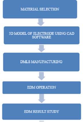
3. Experimental details
3.1 MATERIAL SELECTION
The material selected for manufacturing of EDM electrode is Stainless steel 316L.Copper is the
most widely used EDM electrode material due to the attractive properties like high patrimony and high
mechanical strength. The major problem is that copper is difficult to laser sinter due to its high
reflectivity. Copper is having high reflectivity of 0.99 to laser light of wavelength 10.6 μm. Because of
which copper alloys or materials that give similar results copper is used as non-convectional electrode
3.2 Direct Metal Laser Sintering Machine (DMLS) Work
Laser sintering was done in Intech DMLS, Bangalore, with the EOSINT M 280 Xtended DMLS
machine. The machine includes an ytterbium fiber laser power (Yb) of 400 W and a radius diameter of
0.4 mm. In the construction chamber, there is a construction platform through which a dust delivery
platform and a recovery blade are used to spray dust in to the construction platform. The 3D CAD
2ICOFTIME 2020 IOP Publishing
IOP Conf. Series: Materials Science and Engineering 1013 (2021) 012002 doi:10.1088/1757-899X/1013/1/012002
model of a 10 mm diameter and 25 mm length sample for the DMLS process is modeled using the
"Magics RP" software. The CAD model in STL format will be divided by the "EOS RP Tools"
software. The thickness of the layer must be kept at a constant of 0.06 mm. The segmented data is
uprooting to the proceeding computer of the DMLS machine where the laser path is initiated with the
PSW software. A base plate of the required size of 250 mm X 250 mm X 22 mm in steel is mounted
on the building platform with four screws and the base plate is leveled with a 10 μm resolution
comparator with respect to the coated sheet
3.3 Electrical Discharge Machining (EDM) Work
The machine used for the work is V3525 a 500 X 300 Series Spark Erosion type die sinking EDM machine.
3.4 Experimental Details
The hypothesis test was conducted on the V3525 precision electric discharge machine, which consists of a
working plane, a servo control system and a dielectric power supply system. For the experimentation the current
position was varied from 5 A to 20 A, 9 timed power areas, 9 pulse duration position and a 50-75-micron spark.
Grade 30 EDM oil is used as a dielectric fluid and tests have been accomplished for a peculiar set of input
variables. The number of hypothesis tests and input levels are decided based on the experiment design and input
variables and their stages presented in Table 1. MRR and TWR are calculated using precision digital balancing
of 1 mg and the processing time with the digital clock with precision 1 thousandth of a second and the roughness
of the surface is measured using a machine that measures the roughness of the surface for a sampling length of 5
mm.
Table 1: Input parameter levels
Input Current Pulse on Pulse off
Parameters (amp) Time (μs) Time
(μs)
Symbol A B C
Level 1 10 5 4
Level 2 15 6 5
Level 3 20 7 6
4. Results and Discussions
OPTIMIZATION USING TAGUCHI METHOD
The S / N ratios for MRR are premeditated as indicated in equation.1. The Taguchi method is pre-
owned for the investigation of the result for the response of the processing parameter for wider and
better criteria.
The bigger, the better: S / N ratio = -10log (1 / n.Σn i = 1 1 / yi). . . . . . . . . . . . (1)
When the S / N ratios can be purposive from the discern values, yi, which constitute the empirically
discern value of dissection i and n = 1 is the frequent number of each appraisal in L-9 OA that is
performed.
The scrutiny of the variance for the consideration is determined by the Minitab software and the
results are shown below and the table of answers is shown below
3ICOFTIME 2020 IOP Publishing
IOP Conf. Series: Materials Science and Engineering 1013 (2021) 012002 doi:10.1088/1757-899X/1013/1/012002
Table 2: Signal to noise ratio table
SI NO. I (Amps) Pulse Pulse MRR(g/min) EWR(g/min) Ra(µm) S/N Ratio
ON OFF ×ࠟ10ࠠ^ (−3)
1 10 5 4 0.0268 0.514 10.47 -15.6382 3.6702
2 10 6 5 0.0285 0.596 11.09 -16.14 3.9048
3 10 7 6 0.0281 0.519 12.3 -17.0346 4.2823
4 15 5 4 0.0424 0.785 13.4 -17.7858 4.7424
5 15 6 5 0.0455 0.839 14.49 -18.4647 5.1248
6 15 7 6 0.0397 1.071 15.04 -18.7957 5.3835
7 20 5 4 0.0825 1.449 15.7 -19.1837 5.7438
8 20 6 5 0.0811 1.698 16.12 -19.4241 5.9663
9 20 7 6 0.0803 2.565 15.82 -19.3257 6.1551
. Table 3: Analysis of Variance of MRR
Source DF Seq SS Contributio Adj SS Adj MS F-value P-value
n
Regressio 3 15.0605 93.85% 15.0605 5.0202 25.45 0.002
n
Amps 1 13.8647 86.40% 13.8647 13.8647 70.28 0
Pulse on 1 1.0824 6.74% 1.0824 1.0824 5.49 0.066
Pulse off 1 0.1134 0.71% 0.1134 0.1134 0.58 0.482
Error 5 0.9864 6.15% 0.9864 0.1973
Table 4: Response for Mean
Level Amps Pulse on Pulse off
1 31.12 26.85 27.09
2 27.45 26.52 26.75
3 21.8 26.99 26.51
Delta 9.32 0.46 0.58
Rank 1 3 2
4ICOFTIME 2020 IOP Publishing
IOP Conf. Series: Materials Science and Engineering 1013 (2021) 012002 doi:10.1088/1757-899X/1013/1/012002
Fig 2: Main effect plot for signal to noise ratio for MRR Fig 3: Main effect plot for means for MRR
Fig 4: Main effect plot for signal to noise ratio for EWR Fig 5: Main effect plot for means for EWR
5. Conclusions
It is determined that current is the vital factor between the different process parameters involved in the
EDM process and the contribution is high in both cases. Based on hypothesis testing, the following
conjecture are furnished: With the increase in current, the value of MRR and EWR is cautiously
expanding. To have a favourable condition, i.e. an increase in MRR and a decrease in EWR, it is
necessary to select a nominal current and also the roughness of the surface increases.With magnifying
current and to maintain a moderate current that will provide a good finish superficial together with a
moderate TWR and MRR
References
[1] Fred L. Amorim , Armin Lohrengel , Norbert Müller , Guenter Schäfer ,Tiago Czelusniak (2013) , “Performance of
sinking EDM electrodes made by selective laser sintering technique”, International Journal of Advanced Manufacturing
Technology , 65:1423–1428 00170-01242670.
[2] Fred L. Amoriml, Walter L. Weingaertner, (2007) “The behavior of graphite and copper electrode on die sinking EDM
of AISI P20 tool steel”, journal f the Brazilian society of Mechanical science and engineering, volume 29, issue 4, ISSN
1806-3691
[3] AzharEqubal , Nitesh Kumar Dixit, Anoop kumarsood,(2013) “Rapid prototyping application in manufacturing of EDM
electrode”, International Journal of Scientific & Engineering Research, volume 4, issue8, ISSN 2229-5518.
[4] NorlianaMohd Abbas , Darius G. Solomon, Md. FuadBahari (2006) “A review on current research trends in electrical
discharge machining (EDM)” ,Volume 47, Issues 7–8, Pages 1214–1228.
[5] P. Raja, G. Ramamoorthi, Dr. G. Nallakumarasamy (2017) “Experimental Analysis and Optimization of Electrical
Discharge Machining on Titanium GR-2 with FEA”, International Journal of Emerging Technologies in Engineering
Research (IJETER), Volume 5, Issue 7.
[6] [6]Cristian Pisarciuc (2014), “a review of unconventional procedures for Manufacturing tool electrodes used in edm”,
Volume 15, issue 3(43), pp- 205-208
5ICOFTIME 2020 IOP Publishing
IOP Conf. Series: Materials Science and Engineering 1013 (2021) 012002 doi:10.1088/1757-899X/1013/1/012002
[7] Brent E. Stucker, Walter L. Bradley, Somchin (Jiab) Norasetthekul , Philip T. Eubank (1995) “The Production of
Electrical Discharge Machining Electrodes Using SLS: Preliminary Results”.
[8] Chandramouli S, Shrinivas Balraj U and Eswaraiah K (2014) “Optimization of Electrical Discharge Machining Process
Parameters Using Taguchi Method”, International Journal of Advanced Mechanical Engineering, Volume 4, issue 4, pp.
425-434.
[9] Dr. M.Indira Rani , Ketan (2014) “Optimization of Various Machining Parameters of Electrical Discharge Machining
(EDM) Process on AISI D2 Tool Steel Using Hybrid Optimization Method”, International Journal of Application or
Innovation in Engineering & Management, Volume 3, Issue 9, ISSN 2319 – 4847.
[10] L.A. Dobrzański, M. Musztyfaga, A. Drygała (2010)“Selective laser sintering method of manufacturing front electrode
of silicon solar cell”, journal of achievement in material and manufacturing engineering ,volume 42 ,issue 1-2,pp 1-9.
[11] Eubank, P.T., and B. Bozkrut,(1992) "Recent Developments in Understanding the Fundamentals of Spark Erosion for
Composite Materials, in Machining of Composite Materials , pp 159-166.
[12] Tobin, J.R., B. Badrinarayan, lW. Barlow, J.J. Beaman, and D.L. Bourell, "Indirect Metal Composite Part Manufacture
Using the SLS Process", Solid freeform Fabrication Symposium, pp 303-307.
6You can also read