Passive Bistatic Radar (PBR) for harbour protection applications
←
→
Page content transcription
If your browser does not render page correctly, please read the page content below
Passive Bistatic Radar (PBR) for harbour protection
applications
D. W. O’Hagan*, A. Capria†, D. Petri†, V. Kubica‡, M. Greco§, F. Berizzi†§, A. G. Stove**
* Fraunhofer-FHR, Wachtberg, Germany
†
CNIT – RaSS (Radar and Surveillance Systems) National Lab., Pisa, Italy
‡
Royal Military Academy, Belgium
§
Dept. of Information Engineering, University of Pisa, Pisa, Italy
** Thales Defence and Mission Systems, Crawley, U.K.
Abstract—In this paper we investigate the feasibility of illegal fishing vessels, hazardous cargo transporters and
using Passive Bistatic Radar, PBR, to provide security for smugglers. Furthermore, multiple passive sensors could be
a harbour area. There have been numerous publications networked to extend radar coverage and improve target
on the suitability of passive radar for air surveillance localisation.
applications. However, this paper focuses predominantly
on maritime applications. We investigate the ability of II. THE HARBOUR AREA
passive radar to detect, track, and eventually manage,
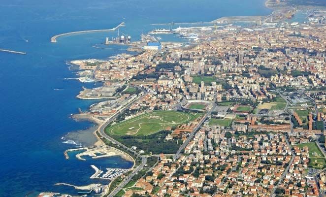
marine vessels (boats). The paper includes a case-study of For this work, the harbour of Livorno (Leghorn), Italy, has
the Livorno Harbour in Italy. Livorno has been chosen as been taken as a realistic case study to assess the capability of
it represents a busy maritime hub. Simulations are passive radar to monitor harbour traffic. Livorno (Fig. 1) has
provided to determine the theoretical radar performance, been chosen as it presents a favourable scenario, not only for
which are then compared with experimental results from the presence of various targets (including petroleum tankers),
a DVB-T-based passive radar. It will be shown that but also for different kinds of illuminators of opportunity.
passive radars represent a viable solution for harbour
protection applications.
I. INTRODUCTION
A number of nations and organisations have an interest in
investigating the potential of bistatic and passive bistatic
radar to act as a security sensor for the protection of special
areas. The special areas, designated sanctuary zones, of
particular focus in this investigation are important harbour
areas. Harbour protection sensors, therefore, should be
capable of detecting ground-based, marine-based, and
airborne targets.
Other works have shown the relevance of passive radar for
air and ground surveillance of targets. However, the primary Fig. 1. Livorno Harbour
objective of this work is to investigate the use of passive
radar for monitoring marine traffic (ships, etc.) in the Livorno is one of the busiest harbours in Italy. This is
proximity of a harbour. It is not always feasible for port evident from the number of shipping routes in Fig. 2. All of
authorities to invest in an expensive infrastructure of primary the shipping routes from Genoa, in the north of Italy, to the
radars. Therefore, cost-competitive passive radars utilising south of the Mediterranean Sea, pass in front of Livorno,
illuminators of opportunity may provide a better means to yielding an abundance of potential targets.
manage vessel traffic within a harbour. This can include the
monitoring of potentially malevolent operators, such as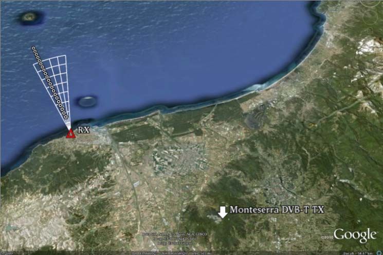
Target Trajectory

                                                                                             20 km

                                                                                                             32 km

Fig. 2. Google Map image of the Livorno region of Italy. The map shows                       Fig. 3. Experiment scenario geometry.
transmitters of opportunity near Livorno. Blue: FM radio, Red: DVB-T,
Yellow: UMTS.

                                                                            IV.    THEORETICAL PERFORMANCE OF A PBR FOR
                      III.   PASSIVE RADAR                                                    HARBOUR PROTECTION
    The principles of passive radar have been                               As part of this feasibility study, simulations have been
comprehensively covered in textbooks such as [1] and [2].                performed to estimate the bistatic radar coverage out into the
However, in this section only the particular specifications of           sea around Livorno. These simulations have been performed
the PBR used in this work will be described.                             using both Matlab and a bistatic radar Mission Planning Tool
                                                                         (MPT) developed at Fraunhofer-FHR, which includes digital
To demonstrate the value of passive radar for harbour                    terrain data of the region of interest.
protection applications, an experimental trial was conducted
at Livorno using a DVB-T passive radar demonstrator                      For both simulations and the experimental trial, the Monte
situated at a site along the coast.                                      Serra DVB-T transmitter was used as the illuminator of
                                                                         opportunity. The relevant system parameters are outlined in
The radar demonstrator was based on a flexible, low-cost,                Table 1.
Software Defined Radio (SDR) concept (a USRP board). The
system consists of a reference and surveillance channel, for                         Table 1. DVB-T passive radar system parameters.
the reception of the reference signal and target signal,                    Parameters                                  Values
respectively. Low-cost Yagi-Uda antennas were used with a
                                                                               EIRP                                     40 dBW
gain of 18 dBi and a half-power-beamwidth (HPBW) of 20°.
Following the antennas and RF front-end, analogue-to-digital                                                                      Height (AMSL):
                                                                                                 Latitude:           Longitude:
converters (ADCs) with 12-bit resolution sampled the DVB-T                   Tx position                                          900 m (incl. 120
                                                                                                43.74719°            10.55498°
                                                                                                                                      m mast)
signal at 64 MS/s. The DVB-T channel of interest during the
experiment had a carrier frequency centred on 818 MHz.                        Livorno
                                                                                                Latitude:            Longitude:   Height (AMSL):
                                                                            Harbour (Rx
                                                                                                43.5295°              10.3079°         2m
                                                                             position)
The receiver was located at the “CSSN-ITE G. Vallauri”
institute in Livorno. The illuminator of opportunity was the               Rx-Tx baseline                                32 km
Monte Serra transmitter and the baseline separation between
the two sites was 32 km, with the primary area of surveillance               Frequency                                 818 MHz
being the sea in front of Livorno. The experimental scenario                  DVB-T
                                                                                                                       7.61 MHz
is shown in Fig. 3                                                           bandwidth
                                                                           Noise figure Rx                                5 dB

                                                                             System loss                                  5 dB

                                                                          Integration time                                0.5 s
                                                                          Assumed bistatic                                    2
                                                                          RCS (for boats)                                30 m

                                                                         To properly utilise a passive radar it is important to
                                                                         characterise, as well as possible, the parameters of the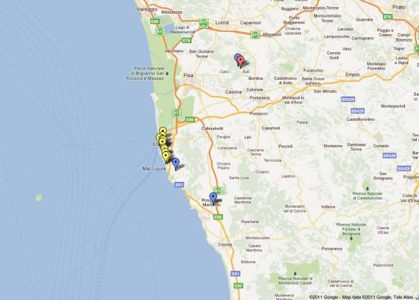
transmitter. In addition to the signal properties, it is critical to
know the azimuth and elevation patterns. The Monte Serra
transmitter is an 8-bay DVB-T antenna, with an omni-
directional azimuth pattern. The elevation pattern has been
simulated in Fig. 4 and shows the HPBW to be approximately
8o. It should be noted that vertical beam tilt has not been
included in the simulated pattern, as the focus of this paper
has been to demonstrate radar performance for detecting
vessels on the sea-surface (the elevation pattern of broadcast
transmitters is usually directed towards the users on the
ground). O’Hagan in [3] provides a broader analysis of the
elevation properties of common illuminators of opportunity.

                                                                         Fig. 5.         Passive radar coverage map plotted on DTED level 1
                                                                                         terrain.

                                                                       Fig. 5 shows that the PBR demonstrator is capable of
                                                                       detecting 30 m2 targets at a range of about 30 km from the
Fig. 4.   Simulated elevation pattern of an 8-bay DVB-T antenna.       harbour with an 11 dB minimum SNR for the detection
                                                                       threshold. The 11 dB detection threshold provides a high
                                                                       confidence of true detection. Future work will look at the
By utilising the system parameters in Table 1, the expected            detection threshold which is actually needed to give an
coverage capability of the passive radar demonstrator has              acceptable false alarm rate with the relatively small number
been estimated using the MPT, which includes level 1 Digital           of resolution cells in the system. It should also be noted that
Terrain Elevation Data (DTED). The coverage map relative               the baseline distance of 32 km provides adequate Direct-
to the Monte Serra DVB-T transmitter and a receiver located            Signal Interference (DSI) isolation to avoid receiver
at Livorno Harbour is shown in Fig. 5. The ability of the              saturation. The residual DSI has been suppressed using
MPT to indicate regions with poor coverage caused by terrain           conventional adaptive filter routines, thereby unmasking the
masking should be noted. The more intense colours (i.e. the            targets of interest.
more black) indicate those areas of highest altitude.
                                                                           Another important feature of the geometry of passive
For the coverage simulation, the receiver antenna has been             radar for harbour protection is that the mode of operation is
approximated as omni-directional in azimuth, except for a              often in an over-the-shoulder configuration. That is, the
20 dB     null   directed    towards     the    transmitter.           transmitter is normally behind the receiver and the targets
                                                                       normally reside along the extended baseline in the pseudo-
                                                                       monostatic region. In this region, the bistatic radar operates in
                                                                       a similar manner to an equivalent monostatic radar (centred at
                                                                       the receiver site) in terms of system resolution performance.
                                                                       This is an important consideration as bistatic range resolution
                                                                       depends on the relative positions of the transmitter, receiver
                                                                       and target. To better evaluate the radar resolution within the
                                                                       considered scenario, a specific map is shown in Fig. 6. The
                                                                       bistatic range resolution regions are plotted on a Cartesian
                                                                       map centred on the receiver (hottest colours equates to the
                                                                       best/finest resolution).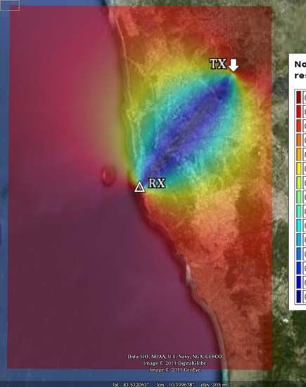
Fig. 8. Expected Doppler frequencies for sh
hips departing from the nearby
harbour (receding fromm receiver).
Within the confines of a harbour, assumed
a here to be 0 nm
to 3 nm, and assuming a vessel speedd of between 5 kts and
10 kts, the asolute Doppler frequency
y will lie between -20 Hz
Fig. 6. Bistatic range resolution variability normaliseed to the equivalent and -60 Hz.
monostatic range resolution. The finest resolution coorresponding to the
monostatic case is approximately 20 m.
A pre-processing technique based
d on NLMS (Normalised
Least Mean Squares) filtering hass been used in order to
V. EXPERIMENTAL RESULTS OF A PBR FOR reduce the DSI in the surveillannce channel. The Cross-
HARBOUR PROTECTION Ambiguity Function (CAF) obtaineed after pre-processing is
presented in Fig. 9.
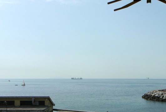
The surveillance area during the acquissition is shown in
the photo in Fig. 7, where the target of iinterest has been
highlighted with a circle. The target in this case is a large boat The echo relative to the ship is clearly visible at a range of
approximately 170 m long. The director elements of the about 2.1 nm with a negative Doppleer frequency equal -32 Hz
surveillance channel Yagi antenna are visiblle at the top of the (i.e.: about 6.5 kts). It should be noted that the target echo is
photo. actually formed by two main peaaks at the same Doppler
frequency. The strongest peak is fu urther from the radar than
the weaker and they correspond to two scattering structures
on the same target, a large bow and another, slightly smaller,
stern structure. The two main peaks visible in the CAF can be
directly associated with the two main scattering structures of
the measured target (see Fig. 10). Th he target length of around
170 m is in accordance with the distance
d of the two main
target peaks in the CAF (around 160 0 m).
Fig. 7. Surveillance area during the acquuisition.
To estimate the expected Doppler frequenncies in a bistatic
scenario, the following equation is used:
G G G G
1 ⎡ r1 ⋅ v r2 ⋅ v ⎤
fd = ⎢ G + G ⎥ (1)
λ ⎣ r1 r2 ⎦
G G
where v is the target velocity vector, r1 is the transmitter
G Fig. 9. DVB-T CAF of the su
urveillance area.
to target velocity vector, and r2 is the targett receiver velocity
vector.
The signal to noise ratio (in Fig. 9), although clearly
In Fig. 8 the expected Doppler frequuencies for ships substantial, is well below what wo ould naively be expected
departing from the nearby harbour are shownn. for a vessel of this size at this rangee. The monostatic RCS of
such a ship could be assumed to be of the order of 10000 m2,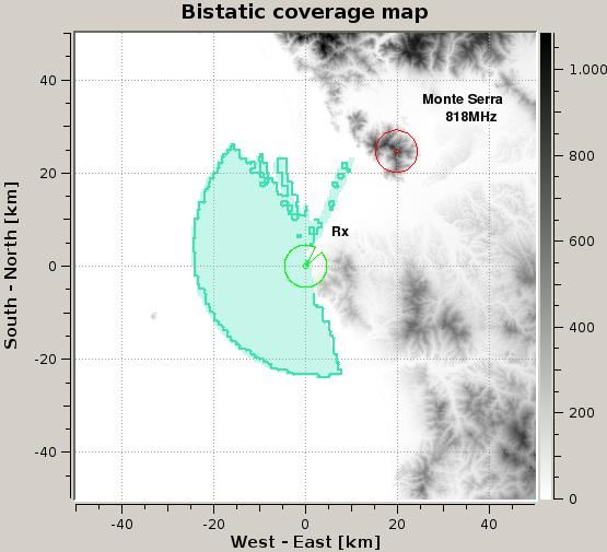
in which case a free-space extrapolation from the coverage                  various size) will be measured during the trial and one key
prediction in Fig. 5 would suggest that the signal to noise                 priority is to determine detection performance against small
ratio would be more than 60 dB. The difference is most                      boats in moderate sea states.
probably due to the effects of low-elevation multipath over
the sea, which will be very significant at long wavelengths
and low sea states, and which was not included in the
calculations which produced Fig. 5.                                                                  REFERENCES

Fig. 10 shows the target of opportunity corresponding to the                [1] N. J. Willis, “Bistatic Radar 2nd Ed.”, SciTech Publishing Inc.
                                                                                New Jersey, 1995.
target in the CAF in Fig. 9. This vessel is typical of the
                                                                            [2] M. Cherniakov, “Bistatic Radar Emerging Technology”, Wiley
marine traffic in the vicinity of Livorno.                                      and Sons, England, 2008.
                                                                            [3] D. W. O’Hagan, “Antenna elevation analysis of common
                                                                                illuminators of opportunity”, 3rd PCL Focus Days, FHR,
                                                                                Wachtberg, May 2011.

   Fig. 10. Target of opportunity corresponding to the measured target in
                                   Fig. 9.

             VI.     ANALYSIS AND CONCLUSIONS
In this preliminary investigation the feasibility of passive
radar for harbour protection applications has been
demonstrated. The work has focused on the busy harbour of
Livorno and has provided site-specific simulations of the
environment. It has been found that it is theoretically possible
to detect targets in the order of 30 m2 to ranges in excess of
40 km from the harbour. This offers detection ranges which
are comparable with a monostatic marine radar and which
may be useful for generating a general vessel-management
scheme.

For the experimental trial, only targets of opportunity were
available from which to derive an evaluation of system
performance. A close-in harbour surveillance area has been
defined as between 0 nm and 3 nm (from the harbour). The
result in Fig. 9 has shown that the DVB-T system has
detected a large vessel which has been confidently identified
as a large ship approximately 170 m long which was seen at a
range of about 2 nm. Future work will compare the signal to
noise ratio seen on the target with what would theoretically
be expected.

This work has demonstrated the feasibility of employing
(potentially) cost-competitive passive radars to secure
harbours. However, future research is required to refine
system performance. Currently research is ongoing to
investigate the impact that bistatic sea clutter has on radar
performance.

Based on the results presented here, a future trial has been
planned with updated hardware and greater system dynamic
range. Furthermore, a range of calibration targets (boats of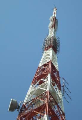

You can also read