PHANTOM-BASED LUMBAR SPINE EXPERIMENTAL INVESTIGATION AND VALIDATION OF A MULTIBODY MODEL
←
→
Page content transcription
If your browser does not render page correctly, please read the page content below
S. Borrelli, et al., Int. J. Comp. Meth. and Exp. Meas., Vol. 9, No. 3 (2021) 226–238
PHANTOM-BASED LUMBAR SPINE EXPERIMENTAL
INVESTIGATION AND VALIDATION OF A MULTIBODY
MODEL
SIMONE BORRELLI1,2, ANDREA FORMAGGIO1,2, VITTORIA CIVILINI1,2 & ANDREA T. LUGAS1,2
1 Department of Mechanical and Aerospace Engineering, Politecnico di Torino, 10129 Turin, Italy.
2 PolitoBIOMedLab, Politecnico di Torino, 10129 Turin, Italy.
ABSTRACT
The study of the biomechanics of the human spine is not yet developed extensively. Recent develop-
ments in this field have heightened the need for observing the spine from a comprehensive perspective
to understand the complex biomechanical patterns, which underlie the kinematic and dynamic responses
of this multiple-joint column. Within this frame of exigence, a joint study embracing experimental tests
and multibody modelling was designed. This study provides novel insights to the segmental contribu-
tion profiles in flexion and extension, analysing different forms of sagittal-plane angles. Moreover,
the validation of the multibody model contributes to defining the key aspects for a consistent spine
modelling as well as it introduces the basis for simulating pathological conditions and post-orthopaedic
surgical outcomes.
Keywords: Lumbar spine multibody model, Lumbar spine phantom, Multi-segment spine, Sawbones
lumbar spine, Spine biomechanics.
1 INTRODUCTION
At present, experimental and numerical investigations are being exploited hand-in-hand to
answer current biomechanical issues effectively. Therefore, the implementation of a joint
approach has permitted relevant steps forward in the understanding of various biomechanical
aspects, thus permitting relevant improvements in the clinical sphere, such as in surgical or
biomedical procedures [1–5], implants realisation [6–12] and prosthesis design [13–17]. On
the one hand, experimental analysis provides further insights into materials characterisation
at different scales [18–26], objectifies clinical qualitative outcomes [27–35] and lets numeri-
cal models be validated [36]. On the other hand, numerical studies allow studying wider test
scenarios and inferring physical quantities otherwise tough to figure out because of feasibility
and costs reasons [37–50]. Despite human joint kinematic mechanism and intersegmen-
tal forces distribution in human joints have revealed to be a fertile topic for this twofold
approach, far too little attention has been paid to investigate load-motion response of mul-
ti-level segment of human spine. So far, indeed, experimental studies have mainly reported
dynamic responses of single intervertebral joints (functional spinal units [FSU]), providing
scant attention to spine’s comprehensive biomechanical behaviour [51,52]. Consequently,
even the consistency of numerical multi-segment models has been negatively affected since
in silico models can only be partially validated by those local results [53–55]. In this frame-
work, the current work intends to provide a joint experimental and numerical contribution
to the representation of multi-level lumbar spine biomechanics. In particular, this study set
out to assess experimentally the global rotation of a lumbar segment phantom loaded by
flexion-extension moments and to validate the corresponding multi-segmental multibody
model, discerning the compressive load effects.
© 2021 WIT Press, www.witpress.com
ISSN: 2046-0546 (paper format), ISSN: 2046-0554 (online), http://www.witpress.com/journals
DOI: 10.2495/CMEM-V9-N3-226-238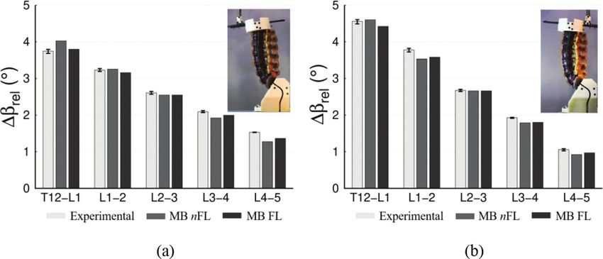
S. Borrelli, et al., Int. J. Comp. Meth. and Exp. Meas., Vol. 9, No. 3 (2021)   227

                         2 IN VITRO AND IN SILICO METHODS
This study performed an experimental and numerical joint analysis, providing a compre-
hensive insight on the lumbar segment of human spine. The research work consisted of two
complementary sections: first, a Sawbones (Sawbones Europe AB, Malmö, Sweden) lumbar
spine phantom was characterised in flexion-extension motion and second, a multibody model
was designed in MSC Adams environment (MSC Software, Hexagon Corporate Services
Ltd., UK). The set up used during experimental tests was re-created in the numerical environ-
ment in terms of geometry and load characteristics applied; this way, a consistent comparison
between experimental and in silico results was achievable.

2.1 Experimental tests

The experimental tests were performed on a Sawbones spinal phantom replicating not only
the lumbar segment but also the adjacent vertebrae T12 and S1 (SKU3430). The phantom
includes the intervertebral discs and the main ligaments; authors well distinguished the
anterior and posterior longitudinal ligaments, ligamenta flava, intertransverse ligaments,
supraspinal and interspinal ligaments. The latter two were created together.
   Flexion and extension tests were realised by applying motion-control linear loadings with
a linear-torsion test machine (Instron E3000, Instron Corporation, Norwood, MA, USA).
Each test was run at a displacement rate of 20 mm/min aiming to reduce the viscous effects
given by the materials representing ligaments and intervertebral discs which could generate
adverse effects; the maximum linear displacement of the machine actuator was set at 10 mm.
These parameters were settled so that they could result suitable to the aim of the work and,
with the intention of future studies involving the phantom, to preserve its integrity. Both
flexion and extension tests consisted of five different replicas. For each replica, the initial
position of the model was not in contact with the test machine, thus resulting slacked. Conse-
quently, since the experimental set up did not introduce an initial pre-stressed condition, the
obtained force-displacement curves were re-aligned at 1N threshold (less than the 2% of the
maximum load recorded), compensating the initial experimental noise. The experimental set
up configuration is shown in Fig. 1: the load was transmitted to the upper extremity through
spherical and translational joints, suitably designed to apply a load with a constant arm with
respect to the global constraint at S1.
   The test machine-phantom couplings were specifically designed in CAD environment and
3D printed (StratasysuPrint SE Plus, Stratasys Ltd., Eden Prairie, MN, USA) to hold both
ends of the lumbar phantom; moreover, they were prepared to account for the anatomical
space orientation of the lumbar spine. Additionally, each test was recorded with a CANON
EOS 5D MarkII camera (Canon Inc. Tokyo, Japan) in order to analyse vertebrae’s kinematic
patterns along the sagittal plane. To do so, markers were manually positioned on the centre
of vertebral bodies and spinous processes and the planar motion tracking was post-processed
by the means of GOMCorrelate software.

2.2 Multibody modelling

The multibody model was designed starting from the vertebral CAD geometry made avail-
able by Sawbones, which declared a correspondence with the physical model. Passive
elements were added to characterise the model with the same anatomical features of the
aforementioned phantom. Averaged density of each vertebra, taking care of both cortical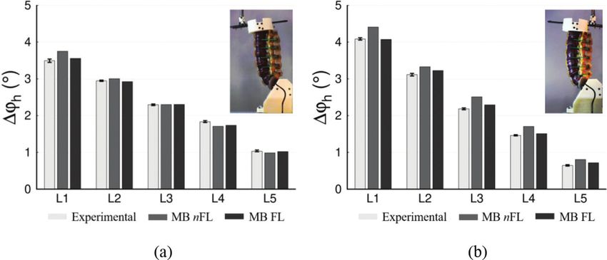
228 S. Borrelli, et al., Int. J. Comp. Meth. and Exp. Meas., Vol. 9, No. 3 (2021)
Figure 1: In vitro and in silico set up: (a-b) flexion, (c-d) extension.
and cancellous bone, was suggested by previous literature works [56–58], and the resulting
masses were in accordance with previous in vitro studies [58]. Furthermore, facet joints were
not only modelled as contact forces between the vertebral bodies, but attractive forces were
also added oriented along the surfaces of the facets in order to limit the relative motion,
accordingly to the permitted physiological ones.
Ligaments: The model distinguished the anterior (ALL) and posterior (PLL) longitudinal
ligaments, ligamenta flava (LF right-left), supraspinal (SSL) and interspinal (ISL) ligaments
and intertransverse ligaments (ITL right-left) for each FSU. The insertion points were posi-
tioned based on anthropometric data, and a particular focus was given to those spanning the
entire lumbar segment, in order to respect the intrinsic spine’s curvature. In vitro studies
showed that spine’s ligaments know a pre-strained condition when the spine is at upright neu-
tral position and characterised by stress–strain curve with two main distinguishable regions:
(1) non-linear segment (toe region) and (2) linear segment. Due to these aspects, it is widely
spread in multibody modelling literature to reproduce ligaments’ biomechanical behaviour
through tension-only force constrained to follow the line of sight between their attachments
[57, 59–63]. Accordingly, all the ligaments were described as a pre-tensioned spring element
in parallel to a damper. The rest length l0 was inversely computed from the distance between
the defined attachment points and the pre-strains ε 0 . Table 1 reports the assigned initial strain
of ligaments, ε 0 , and the strain at the toe-linear regions transaction, 2ε r ; all the values fall
within the physiological ranges provided by in vitro studies [62, 64–66]. Starting from the
suggested mechanical characterisation given by Putame et al. [2], we developed the following
l − l0
law to describe ligaments’ stress–strain (given ε = ):
l0
ε ≤ 0 0
ε2
− cvrel l
ε ≤ 2ε r − 0.25kn ()
ε > 0 εr (1)
ε > 2ε
r − kn ( ε − ε r ) − cvrel l
()
S. Borrelli, et al., Int. J. Comp. Meth. and Exp. Meas., Vol. 9, No. 3 (2021)           229

Where kn corresponds to a stiffness per unit strain [N], calculated from data provided by
Pintar et al. [63], c is the damping constant, l and vrel are the distance and relative velocity
of ligament’s attachment points, respectively. The choice to go to adimensioned stiffnesses
guarantees the removal of possible biases due to different initial lengths between in vitro and
in silico data. Finally, little adjustments were performed in order to make each taut length fall
in its corresponding toe region range after the dynamic transitory.
   Intervertebral discs: The implementation of the 6DOF of the intervertebral discs was
obtained by the means of bushing force elements, typically described as non-coupled stiff-
ness and damping matrices. Rotational and translational stiffnesses were initially extracted
from reference values [58, 67–69], and then slightly adjusted with respect to the experimental
behaviour revealed. Intervertebral discs were supposed at rest in the original spine stance of
Sawbones CAD geometry. The orientation of discs’ reference system was set for each FSUin
order to comply withits local geometry. Therefore, the longitudinal axis was directed along
the conjunction line of the centroids of the adjacent endplates, while the anterior–posterior
axis parallel to the line joining the endplate centroid and the spinous process midpoint of the
upper vertebra. The subsequent third axis was directly obtained by the previous ones to get a
right-handed reference system.
   Pre-load: A compressive pre-load aims to simulate the physiological compressive load
that the lumbar spine encounters supporting the weight of the upper part of the body. The
pre-load was designed in forms of a follower load of 800 N, also satisfying the absence of
induced transmission of moment or shear forces to the vertebrae. In the multibody environ-
ment, this kind of pre-load was created by compressing each bushing with a force acting
along each disc’s longitudinal axis, approximately passing through each FSU’s instantaneous
center of rotation [70–73].
   Contacts: The only spots where contacts could take place where in correspondence of
adjacent vertebrae’s facet joints. Thus, deformable contacts were settled to be consistent with
the particular cartilage present therein. The following relationship was adopted:

                                        Fc = K δ e + C (δ ) δ                                       (2)

Where K is the contact stiffness, δ and δ are the penetration depth displacement and velocity,
respectively, e is a non-linear scaling factor, and C is a sigmoid damping function based on δ .
Values were extracted by previous studies [53]. Due to the small entities of the displacement
applied, contacts appeared during extension only at the end of the motion.

Table 1: Values of pre-strain ε 0 and strain at transaction from toe region to linear region,
           ε l = 2ε r . All the ligaments presented in the multibody model are listed. ALL:
          anterior longitudinal ligament, PLL: posterior longitudinal ligament, LF: ligamen-
          tum flavum, ITL intertransverse ligament, SSL: supraspinous ligament.
                                                 Ligaments
         ALL             PLL             LF                 ISL             ITL              SSL
  ε0     5.3%            6%              7.0%               4.3%            7.0%             -6.0%
  εl     14.0%           13.0%           18.0%              12.0%           15.0%            12.0%
230 S. Borrelli, et al., Int. J. Comp. Meth. and Exp. Meas., Vol. 9, No. 3 (2021)
Two multibody models, differing only for the presence of the compressive follower-load,
were compared with the experimental results in a twofold way, dynamic and kinematic. On
the one hand, flexion-extension moment-angle behaviours of the in silico models were com-
pared to the one resulted experimentally. Experimentally, the moment was obtained from
the sagittal vertical force measured by the load-cell of the testing machine multiplied by its
constant arm; the angle measured, named ϑS 1,T 12 , was formed by the vertical axis and the line
joining the center of mass of S1 (obtained from the multibody and add as a marker on the S1
constraint) and the T12 vertebral body center. The angular displacement was post-processed
thanks to the motion tracking tool.
Vertebrae’s range of motions (ROM) were considered in a double form: first, we measured
the variation of the angle described by the vertical axis and the line joining the centres of mass
of adjacent vertebral bodies (CMVB), ∆βrel; second, we measured the variation of the hori-
zontal angles of the lines joining the center of the spinous processes and their corresponding
vertebral CMVB., ∆ϕh. The ∆βrel provides details about the relative displacements between
vertebrae, while the ∆ϕh gives evidence of the variation of orientation of each vertebra.
3 RESULTS
3.1 Dynamic aspects investigation
Experimental tests reveal an optimal reproducibility both in flexion and extension motion-
control loads: in flexion, the momentum calculated at the maximum angular displacement
(2°) shows a standard deviation of 0.15 N*m less than the 4.4% of the corresponding mean
value. Concerning the extension moment, the deviation from one replica to the other is even
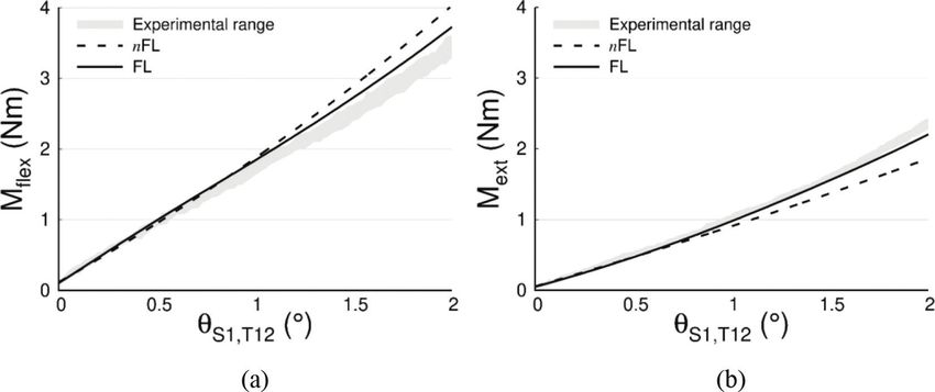
less (0.05 N*m, 2.1 %). Figure 2 outlines, concurrently with the experimental results, the
moment-angle profile of the two in silico models: the one without preload (nFL) and the
other subjected to 800 N of follower load (FL). Interestingly, the rachis phantom shows a
stiffer response in flexion than in extension along the small angular displacements investi-
Figure 2: Bending moment applied vs angular global displacement ϑS 1,T 12 . The experimental
range represents the range of variation obtained from the five test replicas. (a)
Flexion motion; (b) extension motion.S. Borrelli, et al., Int. J. Comp. Meth. and Exp. Meas., Vol. 9, No. 3 (2021) 231
gated. Concerning the numerical curves, the follower load has a marked impact as the angle
increases. In both cases, the application of the follower-load enables the model to describe
better the experimental pattern.
At 2° of flexion, the nFL curve diverges from the experimental mean value by a deviation
of 0.8 N*m (23%). Conversely, the FL curve overestimates the experimental results with a
lower error, maximum at 2° of bending: 0.31 N*m (9%).
In extension, the FL curve displays a satisfactory moment-angle profile with respect to
experimental data: the model load curve fell within the experimental range for most part of
the plot, and the maximum separation from it, amounts to -0.16 N*m (-6.9 %). The model
without pre-load assumes more deviation from all the other cases as the maximum extension
moment differs of -0.71 N*m (- 30.2%).
3.2 Kinematic aspects investigation
Finally, the kinematic analysis demonstrates good consistency between the in silico mod-
els and the lumbar phantom. Figures 3 and 4 illustrate the ROM (∆βrel and ∆ϕh) calculated
as the difference of the angles at rest configuration and at 2° bended. Results show a
cranio-caudally angular displacement decreasing pattern: upper vertebrae display greater
mobility than the distal ones. The high reproducibility of the experimental tests is con-
firmed by the low variability of kinematic results, almost negligible. Furthermore, extension
motion-control loading induces wider variation of angles for upper vertebrae: T12-L1 and
L1-L2 ∆βrel are almost 1° greater than in flexion. This cannot be said for the lower part of
the lumbar segment, where L3-L4 behaviour is almost the same in the two circumstances
and L4-L5 demonstrates a more pronounced mobility in flexion (0.5° greater). Therefore,
the gradient of ∆βrel ranges along the spine segment reveals being higher in extension
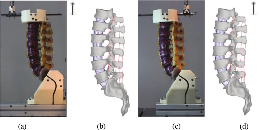
than in flexion. The chart in Fig. 4, reporting the results of ∆ϕh, illustrates interesting
aspects: the direction of the motion-control loading seems not varying the orientation
variances, except for the extremes of the lumbar segment. Indeed, L1 registers an incli-
nation greater of 0.6° in flexion than in extension, while L5’s pitch angle decreases of
almost 0.5° in extension.
Figure 3: Variation of the angle created by two consecutive CMVBs and the vertical axis,
∆βrel. Experimental values (grey) are presented with their range obtained from the
five replicas. (a) Flexion motion applied; (b) extension motion applied.232 S. Borrelli, et al., Int. J. Comp. Meth. and Exp. Meas., Vol. 9, No. 3 (2021)
Figure 4: Singular vertebra angle, ∆ϕh, formed by spinous processes - CMVB connecting line.
Experimental values (grey) are presented with their range obtained from the five
replicas. (a) Flexion motion applied; (b) extension motion applied.
Finally, observing the in silico models, it is possible to assess that the follower loaded
multibody model reveals a very strong kinematic accuracy since in almost all cases it provides
angular values included in the experimental range. On the contrary, the multibody model not
pre-compressed generally shows larger estimates.
4 DISCUSSION
The purpose of the current study was to determine the comprehensive behaviour of the lum-
bar spine phantom when subjected to flexion-extension motion-control load. Moreover, two
multibody models were recreated starting from its geometry to understand whether the intro-
duction of a follower load provided greater adherence to the experimental results.
In our study, the load resulted applied to the extremity of the phantom is consistent with
the ones applied during in vitro tests [70, 74]. Anyway, our study makes use of a linear
motion-control load to execute the torque actions on the phantom, whereas in literature, the
adoption of a pure-moment loading is spread [75]: the resulted stiffer behaviour in flexion
than in extension is not fully in accordance with in vitro state of art [70, 76–78]. Authors sup-
posed that the reason of this discrepancy could be led by the way of load application, which
could influence the behaviour of the spine (motion-control vs load-control). Moreover, the
motion was not applied directly to the extremity of the phantom but through a constant arm.
Finally, another aspect to keep into consideration is that in [77] the bending stiffness of a
lumbar phantom resulted greater in flexion than in extension as highlighted in this study.
Finally, the designing of the numerical multibody models corroborates the effects of the
follower load depending on the direction of the bending, already registered in in vitro and in
silico studies. Anteriorly, the follower load induces an increasing bending ROM under for a
given load, while posteriorly, it is the opposite.
Besides that, the introduction of the follower load makes the multibody model fit to the
experimental results, both in terms of moment-angle profile and kinematic analysis and allows
the numerical multibody model to be considered validated with respect to the Sawbones
phantom. Therefore, starting from the validated numerical model both spinal pathological
conditions and post-orthopaedic surgical outcomes can be consistently simulated. This way,
future studies will be pursued to objectify their effects and compare them with the corre-S. Borrelli, et al., Int. J. Comp. Meth. and Exp. Meas., Vol. 9, No. 3 (2021) 233
sponding physiological results. To the best knowledge of the authors, this aspect has not been
exploited yet in spinal biomechanics literature[79, 80].
5 DECLARATION OF COMPETING INTEREST
None of the authors have any conflicts of interest to disclose.
REFERENCES
[1] Logozzo, S., Kilpelä, A., Mäkynen, A., Zanetti, E.M. & Franceschini, G., Recent
advances in dental optics - Part II: Experimental tests for a new intraoral scanner.
Optics and Lasers in Engineering, 54, pp. 187–196, 2014. https://doi.org/10.1016/j.
optlaseng.2013.07.024
[2] Putame, G., et al., Surgical treatments for canine anterior cruciate ligament rupture:
Assessing functional recovery through multibody comparative analysis. Frontiers
in Bioengineering and Biotechnology, 7, pp. 1–11, 2019. https://doi.org/10.3389/
fbioe.2019.00180
[3] Terzini, M., Bignardi, C., Castagnoli, C., Cambieri, I., Zanetti, E.M. & Audenino, A.L.,
Ex vivo dermis mechanical behavior in relation to decellularization treatment length.
The Open Biomedical Engineering Journal, 10, pp. 34–42, 2016. https://doi.org/10.21
74/1874120701610010034
[4] Putame, G., et al., Application of 3D Printing Technology for Design and Manufacturing
of Customized Components for a Mechanical Stretching Bioreactor. Journal of Health-
care Engineering, Article ID 3957931, 2019. https://doi.org/10.1155/2019/3957931
[5] Zanetti, E.M., et al., A structural numerical model for the optimization of double pelvic
osteotomy in the early treatment of canine hip dysplasia. Veterinary and Comparative
Orthopaedics and Traumatology, 30(4), pp. 256–264, 2017. https://doi.org/10.3415/
vcot-16-05-0065
[6] Putame, G., Pascoletti, G., Terzini, M., Zanetti, E.M. & Audenino, A.L. Mechanical
behavior of elastic self-locking nails for intramedullary fracture fixation: A numerical
analysis of innovative nail designs. Frontiers in Bioengineering and Biotechnology, 8,
pp. 1–10, 2020. https://doi.org/10.3389/fbioe.2020.00557
[7] Calì, M., Pascoletti, G., Gaeta, M., Milazzo, G. & Ambu, R., A new generation of bio-
composite thermoplastic filaments for a more sustainable design of parts manufactured
by FDM. Applied Sciences, 10(17), p. 5852, 2020. https://doi.org/10.3390/app10175852
[8] Corapi, D., Morettini, G., Pascoletti, G. & Zitelli, C., Characterization of a polylactic
acid (PLA) produced by fused deposition modeling (FDM) technology. Procedia Struc-
tural Integrity, 24, pp. 289–295, 2019. https://doi.org/10.1016/j.prostr.2020.02.026
[9] Calì, M., Pascoletti, G., Gaeta, M., Milazzo, G. & Ambu, R., New filaments with natural
fillers for FDM 3D printing and their applications in biomedical field. Procedia Manu-
facturing, 51, pp. 698–703, 2020. https://doi.org/10.1016/j.promfg.2020.10.098
[10] Zanetti, E.M., et al., Modal analysis for implant stability assessment: Sensitivity of this
methodology for different implant designs. Dental Materials, 34(8), pp. 1235–1245,
2018. https://doi.org/10.1016/j.dental.2018.05.016
[11] Dichio, G., et al., Engineering and manufacturing of a dynamizable fracture fixa-
tion device system. Applied Sciences, 10(19), p. 6844, 2020. https://doi.org/10.3390/
app10196844
[12] Lugas, A.T., et al., In vitro simulation of dental implant bridges removal: Influence of
luting agent and abutments geometry on retrievability. Materials (Basel), 13, pp. 1–11,
2020. https://doi.org/10.3390/ma13122797234 S. Borrelli, et al., Int. J. Comp. Meth. and Exp. Meas., Vol. 9, No. 3 (2021)
[13] Putame, G., Pascoletti, G., Franceschini, G., Dichio, G. & Terzini, M., Prosthetic
Hip ROM from multibody software simulation. Proceeding of Annual International
Conference of the IEEE Engineering in Medicine and Biology Society (EMBC), pp.
5386–5389, 2019. https://doi.org/10.1109/embc.2019.8856993
[14] Lugas, A.T., et al., In vitro impact testing to simulate implant-supported prosthesis
retrievability in clinical practice : Influence of cement and abutment geometry. Materi-
als (Basel), 13(7), p. 1749, 2020. https://doi.org/10.3390/ma13071749
[15] Terzini, M., Di Pietro, A., Aprato, A., Artiaco, S., Massè, A. & Bignardi, C., Are sup-
rapectineal quadrilateral surface buttressing plates performances superior to traditional
fixation ? A finite element analysis. Applied Sciences, 11(2), p. 858, 2021. https://doi.
org/10.3390/app11020858
[16] Terzini, M., et al., Multibody modelling of ligamentous and bony stabilizers in the
human elbow. Muscles, Ligaments and Tendons Journal, 7, pp. 493–502, 2017. https://
doi.org/10.11138/mltj/2017.7.4.493
[17] Bignardi, C., et al., Pelvic manipulator for fractures reduction. International Jour-
nal of Radiology and Imaging Technology, 9, pp. 570–580, 2018. https://doi.
org/10.23937/2572-3235.1510035
[18] Pascoletti, G., Pressanto, M.C., Putame, G., Terzini, M., Audenino, A.L. & Zanetti,
E.M., On-site testing of sutured organs: An experimental set up to cyclically tighten
sutures. Journal of the Mechanical Behavior of Biomedical Materials, 109, pp. 103803,
2020. https://doi.org/10.1016/j.jmbbm.2020.103803
[19] Pascoletti, G., et al., Dynamic characterization of the biomechanical behaviour of
bovine ovarian cortical tissue and its short-term effect on ovarian tissue and follicles.
Materials (Basel), 13(17), p. 3759, 2020. https://doi.org/10.3390/ma13173759
[20] Pascoletti, G., Pressanto, M.C., Putame, G., Terzini, M., Franceschini, G. & Zanetti,
E.M., Design of a loading system for cyclic test on sutured organs. MethodsX, 7(7), p.
100988, 2020. https://doi.org/10.1016/j.mex.2020.100988
[21] Pascoletti, G., Pressanto, M.C., Putame, G., Terzini, M., Franceschini, G. & Zanetti,
E.M., Data from cyclic tensile tests on sutured organs to evaluate creep behaviour,
distraction, and residual thread strength. Data Brief, 30, p. 105644, 2020. https://doi.
org/10.1016/j.dib.2020.105644
[22] Belviso, I., et al., Decellularized human dermal matrix as a biological scaffold for car-
diac repair and regeneration. Frontiers in Bioengineering and Biotechnology, 8, p. 229,
2020. https://doi.org/10.3389/fbioe.2020.00229
[23] Zanetti, E.M., Perrini, M., Bignardi, C. & Audenino, A.L., Bladder tissue passive
response to monotonic and cyclic loading. Biorheology, 49, pp. 49–63, 2012. https://
doi.org/10.3233/bir-2012-0604
[24] Bhushan, B., Galasso, B., Bignardi, C., Nguyen, C.V., Dai, L. & Qu, L., Adhesion, fric-
tion and wear on nanoscale of MWNT Tips and SWNT and MWNT arrays. Nanotech-
nology, 19, p. 125702, 2008. https://doi.org/10.1088/0957-4484/19/12/125702
[25] Peluccio, M.S., Bignardi, C., Lombardo, S., Montevecchi, F.M. & Carossa, S., Compar-
ative study of nanomechanical properties of cements used in teeth restoration. Journal
of Physics: Condensed Matter, 19, p. 395003, 2007. https://doi.org/10.1088/0953-
8984/19/39/395003
[26] Serino, G., Gusmini, M., Audenino, A.L., Bergamasco, G., Ieropoli, O. & Bignardi,
C., Multiscale characterization of isotropic pyrolytic carbon used for mechanical heart
valve production.Processes, 9, p. 338, 2021. https://doi.org/10.3390/pr9020338S. Borrelli, et al., Int. J. Comp. Meth. and Exp. Meas., Vol. 9, No. 3 (2021) 235
[27] Pascoletti, G., et al., A novel technique for testing osteointegration in load-bearing con-
ditions. WIT Trans. Engeering & Sciences, 124, pp. 187–194, 2019.
[28] Aldieri, A., et al., Osteoporotic hip fracture prediction: Is T-score-based criterion
enough? A hip structural analysis-based model. Journal of Biomechanical Engineer-
ing, 140(11), Art no. 111004, 2018. https://doi.org/10.1115/1.4040586
[29] Bignardi, C., Zanetti, E.M., Terzini, M., Ciccola, A.R., Schierano, G. & Audenino,
A.L., Reliability, learnability and efficiency of two tools for cement crowns retrieval in
dentistry. The Open Biomedical Engineering Journal, 12(1), pp. 27–35, 2018. https://
doi.org/10.2174/1874120701812010027
[30] Terzini, M., Bignardi, C., Castagnoli, C., Cambieri, I., Zanetti, E.M. & Audenino,
A.L., Dermis mechanical behaviour after different cell removal treatments. Medical
Engineering & Physics, 38, pp. 862–869, 2016. https://doi.org/10.1016/j.medeng-
phy.2016.02.012
[31] D’Amelio, P., et al., Bone mineral density and singh index predict bone mechanical
properties of human femur. Connective Tissue Research, 49, pp. 99–104, 2008. https://
doi.org/10.1080/03008200801913940
[32] Bellia, E., Boggione, L., Terzini, M., Manzella, C. & Menicucci, G., Immediate loading
of mandibular overdentures retained by two mini-implants: A case series preliminary
report. The International Journal of Prosthodontics, 31, pp. 558–564, 2018. https://doi.
org/10.11607/ijp.5589
[33] Menicucci, G., Ceruti, P., Barabino, E., Screti, A., Bignardi, C. & Preti, G., A prelimi-
nary in vivo trial of load transfer in mandibular implant-retained overdentures anchored
in 2 different ways: Allowing and counteracting free rotation. The International Journal
of Prosthodontics, 19(6), pp. 574–576, 2006.
[34] Manzella, C., Burello, V., Bignardi, C., Carossa, S. &Schierano, G., A method to
improve passive fit of frameworks on implant-supported prostheses: An in vivo study.
The International Journal of Prosthodontics, 26(6), pp. 577–579, 2013. https://doi.
org/10.11607/ijp.3326
[35] Manzella, C., Bignardi, C., Burello, V., Carossa, S. & Schierano, G., Method to improve
passive fit of frameworks on implant-supported prostheses: An in vitro study. The Jour-
nal of Prosthetic Dentistry, 116(1), pp. 52–58, 2016. https://doi.org/10.1016/j.pros-
dent.2016.01.006
[36] Aldieri, A., Terzini, M., Bignardi, C., Zanetti, E.M. & Audenino, A.L. Implementation
and validation of constitutive relations for human dermis mechanical response. Medi-
cal & Biological Engineering & Computing, 56(11), pp. 2083–2093, 2018. https://doi.
org/10.1007/s11517-018-1843-y
[37] Pascoletti, G., Catelani, D., Conti, P., Cianetti, F. & Zanetti, E.M., A multibody simula-
tion of a human fall: Model creation and validation. Procedia Structural Integrity, 24,
pp. 337–348, 2019. https://doi.org/10.1016/j.prostr.2020.02.031
[38] Pascoletti, G., Cianetti, F., Putame, G., Terzini, M. & Zanetti, E.M., Numerical simu-
lation of an intramedullary Elastic Nail: Expansion phase and load-bearing behavior.
Frontiers in Bioengineering and Biotechnology, 6, p. 174, 2018. https://doi.org/10.3389/
fbioe.2018.00174
[39] Falvo D’Urso Labate, G., et al., Bone structural similarity score: A multiparametric tool
to match properties of biomimetic bone substitutes with their target tissues. Journal of
Applied Biomaterials & Functional Materials, 14, pp. e277–e289, 2016. https://doi.
org/10.5301/jabfm.5000283236 S. Borrelli, et al., Int. J. Comp. Meth. and Exp. Meas., Vol. 9, No. 3 (2021)
[40] Aimetti, M., Manavella, V., Corano, L., Ercoli, E., Bignardi, C. & Romano, F., Three-
dimensional analysis of bone remodeling following ridge augmentation of compromised
extraction sockets in periodontitis patients: A randomized controlled study. Clinical
Oral Implants Research, 29, pp. 202–214, 2018. https://doi.org/10.1111/clr.13099
[41] Pascoletti, G., Catelani, D., Conti, P., Cianetti, F. & Zanetti, E.M., Multibody models
for the analysis of a fall from height: Accident, suicide, or murder? Frontiers in Bioengi-
neering and Biotechnology, 7, p. 419, 2019. https://doi.org/10.3389/fbioe.2019.00419
[42] Zanetti, E.M., Bignardi, C. & Audenino, A.L., Human pelvis loading rig for static and
dynamic stress analysis. Acta of Bioengineering and Biomechanics, 14, pp. 61–66,
2012. https://doi.org/10.3233/bir-2012-0604
[43] Zanetti, E.M., Crupi, V., Bignardi, C. & Calderale, P.M., Radiograph-based femur
morphing method. Medical & Biological Engineering & Computing, 43, pp. 181–188,
2005. https://doi.org/10.1007/bf02345952
[44] Zanetti, E.M. & Bignardi, C., Mock-up in hip arthroplasty pre-operative planning. Acta
of Bioengineering and Biomechanics, 15, pp. 123–128, 2013.
[45] Manavella, V., Romano, F., Garrone, F., Terzini, M., Bignardi, C. & Aimetti, M., A
novel image processing technique for 3D volumetric analysis of severely resorbed alve-
olar sockets with CBCT. Minerva Stomatologica, 66(3), pp. 81–90, 2017.
[46] Aldieri, A., Terzini, M., Audenino, A.L., Bignardi, C. & Morbiducci, U., Combining
shape and intensity dxa-based statistical approaches for osteoporotic HIP fracture risk
assessment. Computers in Biology and Medicine, 127, Article no. 104093, 2020. https://
doi.org/10.1016/j.compbiomed.2020.104093
[47] Putzer, D., Nogler, M., Terzini, M., Mannara, R. & Bignardi, C., A finite element analy-
sis for a new short stem concept design with spherical bone interface for hip resurfac-
ing. Journal of Mechanical Science and Technology, 9(3), pp. 923–935, 2018. https://
doi.org/10.1007/bf02916333
[48] Terzini, M., Aldieri, A., Nurisso, S., De Nisco, G. & Bignardi, C., Finite element model-
ing application in forensic practice: A periprosthetic femoral fracture case study. Fron-
tiers in Bioengineering and Biotechnology, 8, pp. 1–11, 2020. https://doi.org/10.3389/
fbioe.2020.00619
[49] Terzini, M., Aldieri, A., Rinaudo, L. & Osella, G., Improving the hip fracture risk predic-
tion through 2D finite element models from DXA images: Validation against 3D mod-
els. Frontiers in Bioengineering and Biotechnology, 7, 2019. https://doi.org/10.3389/
fbioe.2019.00220
[50] Vitale, M.C., Chiesa, M., Coltellaro, F., Bignardi, C., Celozzi, M. & Poggio, C., FEM anal-
ysis of different dental root canal-post systems in young permanent teeth. European Jour-
nal of Paediatric Dentistry, 9(3), pp. 111–117, 2008. https://doi.org/10.1111/ipd.12587
[51] Heuer, F., Schmidt, H., Klezl, Z., Claes, L. & Wilke, H.J., Stepwise reduction of func-
tional spinal structures increase range of motion and change lordosis angle. Journal of
Biomechanics, 40, pp. 271–280, 2007. https://doi.org/10.1016/j.jbiomech.2006.01.007
[52] Vinyas, V., Adhikari, R. & Shyamasunder Bath, N., Review on the progress in develop-
ment of finite element models for functional spinal units: Focus on lumbar and lum-
bosacral levels. Malaysian Journal of Medicine and Health Sciences, 16, pp. 66–74,
2020. https://doi.org/10.1097/bsd.0b013e31812e6276
[53] Abouhossein, A., Weisse, B. & Ferguson, S.J., Quantifying the centre of rotation pattern
in a multi-body model of the lumbar spine. Computer Methods in Biomechanics and
Biomedical Engineering, 16, pp. 1362–1373, 2013. https://doi.org/10.1080/10255842.
2012.671306S. Borrelli, et al., Int. J. Comp. Meth. and Exp. Meas., Vol. 9, No. 3 (2021) 237
[54] Zheng, J., Tang, L. & Hu, J., A numerical investigation of risk factors affecting lum-
bar spine injuries using a detailed lumbar model. Applied Bionics and Biomechanics,
Article ID 8626102, 2018. https://doi.org/10.1155/2018/8626102
[55] Schlager, B., Niemeyer, F., Galbusera, F., Volkheimer, D., Jonas, R. & Wilke, H.J.,
Uncertainty analysis of material properties and morphology parameters in numerical
models regarding the motion of lumbar vertebral segments. Computer Methods in Bio-
mechanics and Biomedical Engineering, 21, pp. 673–683, 2018. https://doi.org/10.108
0/10255842.2018.1508571
[56] Ghezelbash, F., et al., Modeling of human intervertebral disc annulus fibrosus with
complex multi-fiber networks. Acta Biomaterialia, 123, pp. 208–221, 2021. https://doi.
org/10.1016/j.actbio.2020.12.062
[57] Rupp, T.K., Ehlers, W., Karajan, N., Günther, M. & Schmitt, S., A forward dynamics
simulation of human lumbar spine flexion predicting the load sharing of intervertebral
discs, ligaments, and muscles. Biomechanics and Modeling in Mechanobiology, 14,
pp. 1081–1105, 2015. https://doi.org/10.1007/s10237-015-0656-2
[58] Christophy, M., Senan, N.A.F., Lotz, J.C. & O’Reilly, O.M., A Musculoskeletal model
for the lumbar spine. Biomechanics and Modeling in Mechanobiology, 11, pp. 19–34,
2012. https://doi.org/10.1007/s10237-011-0290-6
[59] Damm, N., Rockenfeller, R. & Gruber, K., Lumbar spinal ligament characteristics
extracted from stepwise reduction experiments allow for preciser modeling than lit-
erature data. Biomechanics and Modeling in Mechanobiology, 19, pp. 893–910,
2020. https://doi.org/10.1007/s10237-019-01259-6
[60] Panjabi, M.M., et al., Human lumbar vertebrae quantitative three-dimntional anatomy.
Spine (Phila. Pa. 1976), 17, pp. 299–306, 1992. https://doi.org/10.1097/00007632-
199203000-00010
[61] Panjabi, M.M., Goel, V.K. & Takata, K., Physiologic Strains in the Lumbar Spinal Liga-
ments. Spine (Phila. Pa. 1976), 7, pp. 192–203, 1982. https://doi.org/10.1097/00007632-
198205000-00003
[62] Aspden, R.M., Review of the functional anatomy of the spinal ligaments and the
lumbar erector spinae muscles. Clinical Anatomy, 5, pp. 372–387, 1992. https://doi.
org/10.1002/ca.980050504
[63] Pintar, F.A., Yoganandan, N., Myers, T., Elhagediab, A. & Sances, A., Biomechanical
properties oh human lumbar spine ligaments. Journal of Biomechanics, 25, pp. 1351–
1356, 1992. https://doi.org/10.1016/0021-9290(92)90290-h
[64] Nachemson, A.L. & Evans, J.H., Some mechanical properties of the third human lum-
bar interlaminar ligament (ligamentum flavum). Journal of Biomechanics, 1(3), pp.
211–220, 1968. https://doi.org/10.1016/0021-9290(68)90006-7
[65] Chazal, J., et al., Biomechanical properties of spinal ligaments and a histological study
of the supraspinal ligament in traction. Journal of Biomechanics, 18, pp. 167–176,
1985. https://doi.org/10.1016/0021-9290(85)90202-7
[66] Robertson, D.J., Von Forell, G.A., Alsup, J. & Bowden, A.E., Thoracolumbar spi-
nal ligaments exhibit negative and transverse pre-strain. Journal of the Mechanical
Behavior of Biomedical Materials, 23, pp. 44–52, 2013. https://doi.org/10.1016/j.
jmbbm.2013.04.004
[67] Gardner-Morse, M.G. & Stokes, I.A.F., Structural behavior of human lumbar spi-
nal motion segments. Journal of Biomechanics, 37, pp. 205–212, 2004. https://doi.
org/10.1016/j.jbiomech.2003.10.003238 S. Borrelli, et al., Int. J. Comp. Meth. and Exp. Meas., Vol. 9, No. 3 (2021)
[68] Huynh, K.T., Gibson, I., Lu, W.F. & Jagdish, B.N., Simulating dynamics of thoraco-
lumbar spine derived from life MOD under haptic forces. World Academy of Science,
Engineering and Technology, 64, pp. 278–285, 2010.
[69] Meng, X., Bruno, A.G., Cheng, B., Wang, W., Bouxsein, M.L. & Anderson, D.E., Incor-
porating six degree-of-freedom intervertebral joint stiffness in a lumbar spine musculo-
skeletal model - Method and performance in flexed postures. Journal of Biomechanics
Engineering, 137, pp. 1–9, 2015. https://doi.org/10.1115/1.4031417
[70] Patwardhan, A.G., Havey, R.M., Carandang, G., Simonds, J., Voronov, L.I., Ghanayem,
A.J., Meade, K.P., Gavin, T.M. & Paxinos, O., Effect of compressive follower preload
on the flexion-extension response of the human lumbar spine. Journal of Orthopaedic
Research, 21, pp. 540–546, 2003. https://doi.org/10.1016/s0736-0266(02)00202-4
[71] Bell, K.M., Debski, R.E., Sowa, G.A., Kang, J.D. & Tashman, S., Optimization of com-
pressive loading parameters to mimic in vivo cervical spine kinematics in vitro. Journal of
Biomechanics, 87, pp. 107–113, 2019. https://doi.org/10.1016/j.jbiomech.2019.02.022
[72] Volkheimer, D., Malakoutian, M., Oxland, T.R. & Wilke, H.J., Limitations of current
in vitro test protocols for investigation of instrumented adjacent segment biomechan-
ics: Critical analysis of the literature. European Spine Journal, 24, pp. 1882–1892,
2015. https://doi.org/10.1007/s00586-015-4040-9
[73] Bell, K.M., Yan, Y., Hartman, R.A. & Lee, J.Y., Influence of follower load application
on moment-rotation parameters and intradiscal pressure in the cervical spine. Journal of
Biomechanics, 76, pp. 167–172, 2018. https://doi.org/10.1016/j.jbiomech.2018.05.031
[74] Widmer, J., Cornaz, F., Scheibler, G., Spirig, J.M., Snedeker, J.G. & Farshad, M., Bio-
mechanical contribution of spinal structures to stability of the lumbar spine—novel
biomechanical insights. The Spine Journal, 20, pp. 1705–1716, 2020. https://doi.
org/10.1016/j.spinee.2020.05.541
[75] Widmer, J., Fornaciari, P., Senteler, M., Roth, T., Snedeker, J.G. & Farshad, M., Kine-
matics of the Spine Under Healthy and Degenerative Conditions: A systematic review.
Annals of Biomedical Engineering, 47, pp. 1491–1522, 2019. https://doi.org/10.1007/
s10439-019-02252-x
[76] Cripton, P.A., Bruehlmann, S.B., Orr, T.E., Oxland, T.R. & Nolte, L.P., In vitro axial
preload application during spine flexibility testing: Towards reduced apparatus-related
artefacts. Journal of Biomechanics, 33, pp. 1559–1568, 2000. https://doi.org/10.1016/
s0021-9290(00)00145-7
[77] Demetropoulos, C.K., Yang, K.H., Grimm, M.J., Khalil, T.B. & King, A.I., Mechanical
properties of the cadaveric and hybrid III lumbar spines. SAE Technical Paper Series,
107, pp. 2862–2871, 1998.
[78] Panjabi, M.M., Oxland, T.R. , Yamamoto, I. & Crisco, J.J., Mechanical behavior of the
human lumbar and lumbosacral Spine as shown by three-dimensional load-displace-
ment curves. The Journal of Bone & Joint Surgery, 76(3), pp. 413–424, 1994. https://
doi.org/10.2106/00004623-199403000-00012
[79] Zhang, C., Mannen, E.M., Sis, H.L., Cadel, E.S., Wong, B.M., Wang, W., Cheng, B.,
Friis, E.A. & Anderson, D.E., Moment-rotation behavior of intervertebral joints in
flexion-extension, lateral bending, and axial rotation at all levels of the human spine:
A structured review and meta-regression analysis. Journal of Biomechanics, 100,
p. 109579, 2020. https://doi.org/10.1016/j.jbiomech.2019.109579
[80] Oxland, T.R., Fundamental biomechanics of the spine-What we have learned in the past
25 years and future directions. Journal of Biomechanics, 49, pp. 817–832, 2016. https://
doi.org/10.1016/j.jbiomech.2015.10.035You can also read