Photon Spectra of a Bragg Microresonator with Bigyrotropic Filling
←
→
Page content transcription
If your browser does not render page correctly, please read the page content below
hv
             photonics

Communication
Photon Spectra of a Bragg Microresonator with
Bigyrotropic Filling
Svetlana V. Eliseeva * , Irina V. Fedorova and Dmitry I. Sementsov

                                           Department of High Technology Physics and Engineering, Ulyanovsk State University, Lev Tolstoy 42,
                                           432700 Ulyanovsk, Russia; irinkafyodorova@yandex.ru (I.V.F.); sementsovdi42@mail.ru (D.I.S.)
                                           * Correspondence: eliseeva-sv@yandex.ru

                                           Abstract: In this article, we have obtained the transmission spectra of a microresonator structure
                                           with Bragg mirrors, the working cavity of which is filled with a magnetically active finely layered
                                           ferrite-semiconductor structure with material parameters controlled by an external magnetic field.
                                           It is shown that a change in the external field and the size of the cavity (filling layer thickness)
                                           provokes a controlled rearrangement of the transmission spectrum of TM and TE waves. The
                                           polarization characteristics of the microcavity, their dependence on the external field, and the ratio
                                           of the thicknesses of the layers that make up the period of the ferrite-semiconductor structure
                                           are investigated.

                                           Keywords: polarization of light; one-dimensional photonic-crystal; transmission spectra; microcavities

                                           1. Introduction
                                                 Photonic-crystal microresonators (MCRs) have recently attracted the close attention of
                                           researchers both in terms of their fundamental properties and in connection with the wide
                                           possibilities of their practical application. One-dimensional MCRs represent a structure in
                                           which dielectric Bragg reflectors are used as mirrors [1–7]. Microresonators are used to cre-
Citation: Eliseeva, S.V.; Fedorova,        ate a wide class of radiation control devices (switches, modulators, filters) of various ranges,
I.V.; Sementsov, D.I. Photon Spectra       performing the function of amplifying various types of light interaction with a propagation
of a Bragg Microresonator with
                                           medium. Thus, in the optical range, in order to increase the rate of spontaneous emission of
Bigyrotropic Filling. Photonics 2022, 9,
                                           single quantum emitters, resonators based on optical fibers are widely considered, in which
391. https://doi.org/10.3390/
                                           the working cavity is enclosed between Bragg gratings [8–13]. A symmetric photonic
photonics9060391
                                           crystal MCR is formed from two identical dielectric Bragg mirrors (BMs) separated from
Received: 13 May 2022                      each other by a certain distance along their axis, and it is necessary to change the order of
Accepted: 30 May 2022                      the layers in one of the BMs. The area between the mirrors (cavity) is usually filled with an
Published: 31 May 2022                     active medium. Due to the multiple reflection of radiation between the mirrors, standing
Publisher’s Note: MDPI stays neutral
                                           waves (resonator modes) are formed. In plane-parallel resonators, only those modes are
with regard to jurisdictional claims in    supported for which the distance between the mirrors is a multiple of half the propagating
published maps and institutional affil-    radiation wavelength. In this case, transmission resonances are observed in photonic band
iations.                                   gaps (PBGs). Their number, position, and amplitude are determined by the width of the
                                           cavity and the reflection coefficient of the mirrors. For many practical applications, it is
                                           important to be able to tune the resonant frequency of the MCR by changing the external
                                           parameters. Efficient rearrangement of the transmission and reflection spectra of the MCR
Copyright: © 2022 by the authors.          can be achieved by introducing into the cavity between the mirrors a medium whose
Licensee MDPI, Basel, Switzerland.         material parameters depend on easily changed external factors [11–17].
This article is an open access article           In this work, we study the features of the transmission spectrum of a structure MCR
distributed under the terms and            whose working cavity is filled with a magnetically active finely layered structure with
conditions of the Creative Commons
                                           material parameters controlled by an external magnetic field. For this kind of structure
Attribution (CC BY) license (https://
                                           materials, we chose doped semiconductor p-InP and ferrospinel NiFe2 O4 . This choice
creativecommons.org/licenses/by/
                                           (semiconductor and magnet) is due to the fact that the frequencies of the magnetic and
4.0/).

Photonics 2022, 9, 391. https://doi.org/10.3390/photonics9060391                                           https://www.mdpi.com/journal/photonics
Photonics 2022, 9, 391                                                                                                                      2 of 9

                         cyclotron resonances are close and fall into the first band gap of the BMs. In this case, both
                         orthogonally polarized eigenwaves (TE and TM) become controlled by an external magnetic
                         field. The use of this fine-layered structure makes it possible to effectively control the radia-
                         tion passing through the microresonator (and, consequently, reflected). The paper presents
                         the frequency and field dependences of the structure eigenwaves transmission coefficient
                         at different thicknesses of the effective medium filling the working cavity. The polarization
                         characteristics of radiation passing through a MCR and the possibility of polarization
                         control using an external magnetic field are studied.

                         2. Basic Relationships
                               Let us consider a symmetrical MCR formed by two Bragg mirrors (BMs) and a cavity
                         separating them. The period of the BMs consists of two layers of isotropic dielectrics with
                                                                                          √         √
                         permittivity ε 1 and ε 2 and equal optical thicknesses L1 ε 1 = L2 ε 2 . The cavity, the length
                         of which L3 and the permittivity ε 3 = 1, will be filled with a magnetically active flat-layered
                         structure, composed of semiconductor and ferrite layers with thicknesses l1 and l2 (see
                         Figure 1). The material parameters (permittivity and permeability of each of the layers)
                         in the studied high-frequency range are scalar-tensor quantities, i.e., for a semiconductor,
                         this is ε̂ s and µs , for a ferrite, ε f and µ̂ f . In the absence of an external magnetic field, such
                         one-dimensional structure has the properties of the uniaxial crystal with symmetry axis
                         perpendicular to the interfaces between the layers (OZ axis). A plane linearly polarized
                         wave is introduced into the structure along this axis and propagates in it.

                         Figure 1. Sketch of the symmetrical microcavities structure.

                              The action of the magnetic field leads to the anisotropy of the optical properties of the
                         semiconductor and ferrite. For the field H0 oriented in the layer plane along the OX axis,
                         the tensor parameters have the form:

                                                       ε xx      0            0 !               µ xx           0     0 !
                                             ε̂ s =     0       ε yy         ε yz ,   µ̂ f =     0            µyy   µyz .                     (1)
                                                        0       ε zy         ε zz                0            µzy   µzz

                              In this geometry, the corresponding components of the semiconductor permittivity
                         tensor ε yy = ε zz = ε, ε xx = ε k , ε yz = −ε zy = iε a depend on the frequency and external
                         magnetic field as follows [18]:

                                                      ω 2p ων                                  ω 2p                      ε l ω 2p ωc
                                                                     !                                !
                                    ε = εl 1 +                           ,     εk = εl 1 −                ,     εa =                    ,     (2)
                                                  ω (ων2 − ωc2 )                               ωων                     ω (ων2 − ωc2 )

                         wherepthe plasma and cyclotron frequencies of the semiconductor are introduced
                         ω p = 4πe2 n0 /m∗ ε l and ωc = eH0 /m∗ c, ε l is the lattice part of the permittivity, e is the
                         electron charge, n0 and m∗ are the concentration and effective mass of carriers, ων = ω + iν,
                         ν is the relaxation parameter. For ferrite, the components of the tensor magnetic permeabil-
                         ity µyy = µzz = µ, µyz = −µzy = iµ a and µ xx have the form [19,20]: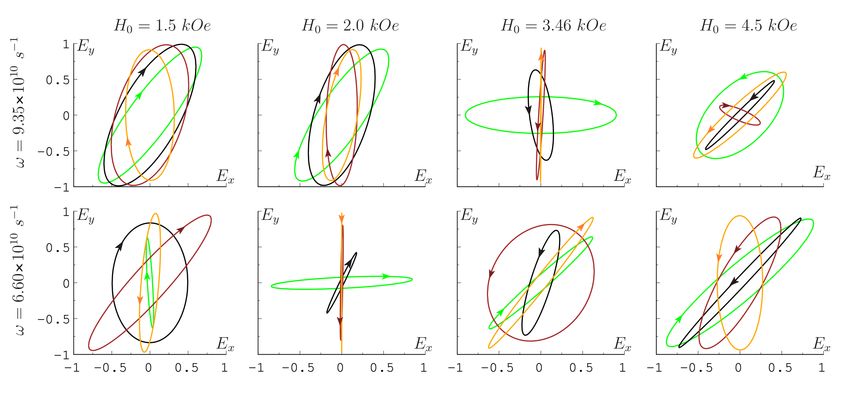
Photonics 2022, 9, 391                                                                                                                   3 of 9

                                                ω M (ω H + i∆ω )                                ωM ω
                                   µ = 1+                         ,            µa =                           ,              µ xx = 1,     (3)
                                                 − ω 2 + 2iω H ∆ω
                                              ω 2H                                    ω 2H   − ω 2 + 2iω H ∆ω

                         where ω M = 4πγM0 , M0 is saturation magnetization, ω H = γH0 , ∆ω = γ∆H is the width
                         of the magnetic resonance line, and γ is the magnetomechanical relationship. In this case,
                         the permeability of the semiconductor is taken equal to unity (µs = 1), and the permittivity
                         of ferrite is ε f = 13.7 (spinel NiFe2 O4 ).
                                Furthermore, we assume that the thickness of the semiconductor and ferrite layers
                         is small compared to the length of the waves propagating in the structure and its period
                         is ls + l f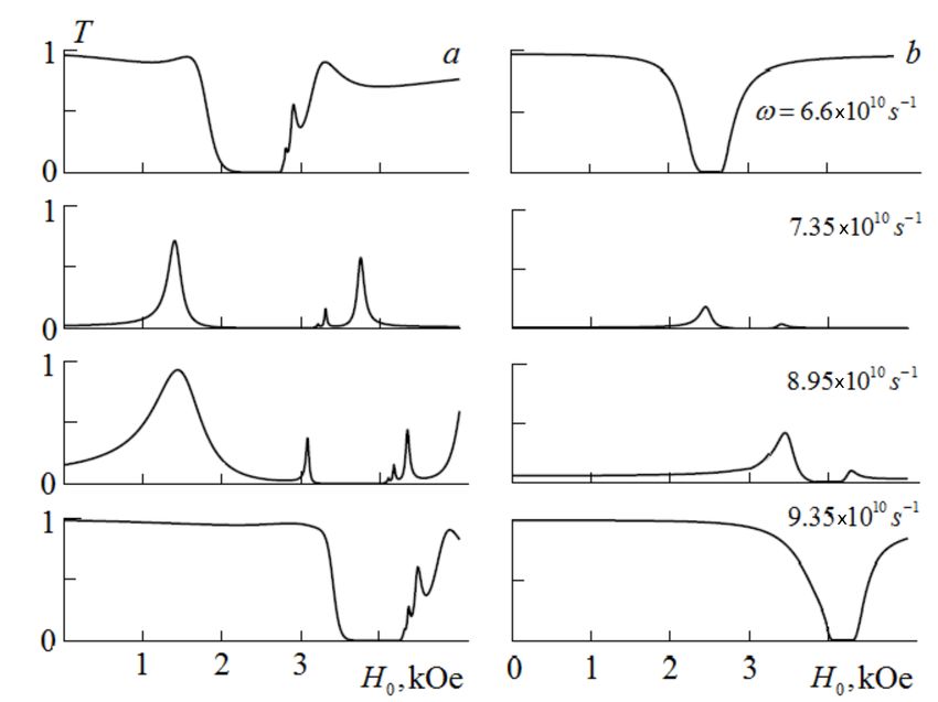
Photonics 2022, 9, 391                                                                                                      4 of 9

                                                                                  k0 ξ j
                                                            cos k j L j       i          sin k j L j !
                                                                                   kj
                                               Nj =       ik j                                           ,   j = 1 − 3,       (6)
                                                                sin k j L j         cos k j L j
                                                         k0 ξ j
                                                                                         √
                         where ξ j = µ j for TE-wave and ξ j = ε j for TM-wave, k1,2 = k0 ε 1,2 are the propagation
                         constants in the layers of the BM, the propagation constants for the effective medium k3TE
                         and k3TM are determined by the relations (4), k0 = ω/c, ω and c are the frequency and the
                         wave speed in the vacuum. If the resonator cavity remains empty, then k3 = k0 .
                              The amplitude reflection and transmission coefficients for the entire MCR structure
                         are determined through the matrix elements of the transfer matrix [23]:

                                                G11 + G12 − G21 − G22                                 2
                                           r=                         ,               t=                          .           (7)
                                                G11 + G12 + G21 + G22                       G11 + G12 + G21 + G22

                              The energy reflection and transmission coefficients in this case have the form R = |r |2 ,
                         T = |t|2 . When absorption in layers is taken into account, the fraction of energy absorbed
                         by the structure is determined by the quantity A = 1 − R − T.
                              To reveal the spectral features of the MCR that arise when the cavity is filled with an
                         effective bigyrotropic medium, let us first consider the distribution of the wave field over
                         a structure with an unfilled cavity. We assume that the period of the BM consists of two
                         layers of isotropic dielectrics Si3 N4 and ZrO2 with permittivity ε 1 = 7.16 and ε 2 = 4.16
                                                             √          √
                         and equal optical thicknesses L1 ε 1 = L2 ε 2 = λ0 /4. Here, λ0 = 2πc/ω0 , where the
                         operating frequency is chosen equal to ω0 = 8 × 10¹⁰ s−1 . In this case, the real thicknesses
                         of the layers are L1 ' 2201 µm and L2 ' 2888 µm. In each of the mirrors, the number of
                         periods is a = 5, and the period of the structure is L1 + L2 = 2052 µm, the thickness of each
                         mirror is L = 1.03 cm.
                              Figure 3a,b shows the distribution over the MCR structure of the normalized electric
                         field | E(z)/E0 |2 squared modulus for different cavity sizes. The operating frequency,
                         for which the distribution of the electric field amplitude is constructed, corresponds to the
                         frequency of the central mode ω0 . The thin line shows the distribution of the permittivity
                         along the longitudinal coordinate of the MCR. It can be seen that, for the structure with
                         L3 = λ0 /2 (a) at its center, the electric field amplitude reaches the minimum, and two
                         maxima occur at the side boundaries of the cavity. In this case, the amplitude of the
                         magnetic field in the center of the cavity reaches the maximum, and at its boundaries with
                         BMs, it reaches the minimum. The incident wave weakly penetrates into the structure, since
                         at the chosen operating frequency the cavity plays the role of a reflecting quarter-wave
                         plate; this follows at L3 = λ0 /4 (b) from the field distribution.

                         Figure 3. Field distribution over the MCR structure with the cavity of thickness L3 = λ0 /2; λ0 /4 (a,b).
Photonics 2022, 9, 391 5 of 9
3. Transmission Spectra of the Microcavity
Let us consider the transformation of the MCR transmission spectrum when its cavity
is filled with an effective medium. Figure 4 shows the frequency dependences of the
transmittance T for the case of an unfilled cavity (left) and a filled one (right). The spectra
were obtained at H0 = 0 for the cavity size L3 = 2λ0 , λ0 , λ0 /2, λ0 /4 (a − d). It can be seen
that the width and number of narrow peaks in the PBG change with increasing L3 . For the
first three values of the unfilled cavity thickness at the band gap center, there is a narrow
transmission peak (defective mode). In the case of a quarter-wavelength thickness (d),
this peak is absent. Note that the effective medium is isotropic in the layer plane (YZ)
when there is no external magnetic field, so the realized spectrum does not depend on the
polarization of the eigenwave propagating in the structure.
When theq cavity is filled with a bigyrotropic effective medium, its optical thickness
opt
L3 = L3 Re εe f µe f is not constant but depends on both the frequency and the magnitude
of the external field. In this case, the phase-matching conditions become field-dependent;
therefore, the nature of the spectrum also depends on the external field and changes
significantly in comparison with the spectra in the absence of the field and, moreover, in the
absence of the cavity filling.
Figure 4. Transmission spectra of the MCR with the vacuum cavity (a–d) and the cavity filled with
a finely layered ferrite-semiconductor medium (e–h) with the thickness L3 = 2λ0 , λ0 , λ0 /2, λ0 /4;
λ0 = 2.36 cm at H0 = 0.
Figure 5 show the transmission spectra of TE (a,c) and TM (b,d) waves of the MCR
filled with an effective medium for two cavity sizes L3 = λ0 /2 (a,b) and λ0 /4 (c,d),
at magnetic field values H0 = 1.5, 2.0, 3.5, 4.5 kOe (curves 1–4). It can be seen that, as the
field increases, the character of the frequency dependence of the transmission coefficient
changes significantly and depends both on the thickness of the effective medium and on
the type of the incident wave.Photonics 2022, 9, 391 6 of 9
Figure 5. Transmission spectra of TE and TM waves with a cavity thickness L3 = λ0 /2 = 1.178 cm
(a,b) and L3 = λ0 /4 = 0.589 cm (c,d) filled with a finely layered medium at different values of the
magnetic field.
Figure 6 shows the external field dependences of the TE and TM waves (a,b) transmis-
sion coefficient at several frequencies and size L3 = λ0 /4 for an MCR with the cavity filled
with an effective medium. It can be seen that for some frequencies there are fields’ intervals
where the transmission of waves of both polarizations is almost complete, and there are
intervals where the wave transmission is complete only for one polarization. The presence
of such intervals in the spectrum makes it possible to use a structure similar to a MCR as
a filter or polarizer controlled by a magnetic field.
Figure 6. Transmission spectra of TE and TM waves (a,b) with a cavity thickness L3 = λ0 /4 =
0.589 cm filled with a finely layered medium at different frequencies.
4. Polarization Characteristics
To determine the polarization characteristics of a MCR with an effective medium, we
assume that the polarization plane of the wave incident on the structure makes angle ψ0
with the OX axis (i.e., with the vector H0 ). The electric field of the wave transmitted through
a MCR can be represented as the sum of the fields of eigenwaves E = E TE + E TM . At the
exit from the MCR, the components of the electric field are determined by the expressionsPhotonics 2022, 9, 391 7 of 9
Ex = E TM = t TM E0 cos ψ0 , Ey = E TE = t TE E0 sin ψ0 . (8)
To describe the transmitted wave polarization state, we introduce the complex polar-
ization variable [24]:
|t TE | TE TM
χ = (tgψ)eiδ = TM ei(δ −δ ) , (9)
|t |
where ψ is the angle of inclination of the ellipse major axis to the axis OX, and δ is the
phase mismatch of eigenwaves when passing through the MCR. The angle ψ and ellipticity
E parameters are determined by the expressions:
2Reχ 2Imχ
tg2ψ = , E = tgφ, sin 2φ = − . (10)
1 − | χ |2 1 − | χ |2
Figure 7 shows the polarization ellipses of the wave transmitted through the structure,
obtained with the orientation of the plane of the wave incident polarization on the structure
ψ0 = π/4, at two frequencies and four values of the parameter θ = 0.5, 1.0, 2.0, 10 (green,
black, brown, and yellow lines, the arrows indicate the direction of vector E motion). It can
be seen from the shape of the polarization ellipses that both the magnitude of the ellipticity
and the angle of inclination of the major axis depend significantly on the frequency, on the
applied magnetic field, and on the ratio of the layer thicknesses in the structure period.
Therefore, these parameters of the wave passing through the MCR are easily controlled
within a fairly wide range.
Figure 7. Polarization ellipses of the transmitted radiation at frequency ω = 6.6 × 10¹⁰ s−1 and
ω = 9.35 × 10¹⁰ s−1 for various values of the field and parameter θ = 0.5, 1, 2, 10 (green, black,
brown, and yellow) arrows show the direction of polarization clockwise and counterclockwise.
5. Discussion
In the present work, when modeling the transmission spectra of a Bragg MCR, we used
the parameters of an impurity semiconductor p-InP and a ferrospinel NiFe2 O4 . Specific
materials of the layered structure were chosen so that the frequencies of the magnetic and
cyclotron resonances were close and fell into the PBG of the BMs. In this case, the change
in the magnetic field leads to a significant change in the character of the transmission
spectrum for waves of both polarizations. Note that, by choosing the materials of ferrite
and semiconductor, it is possible to spread the indicated frequencies into different ranges
(for example, Y3 Fe5 O12 and n-InSb). At the same time, only the TE wave spectrum canPhotonics 2022, 9, 391 8 of 9
be magnetically sensitive at a low operating frequency, and only the TM wave spectrum
can be magnetically sensitive at a high operating frequency. By choosing the materials of
the effective medium layers and changing the BM period, the operating range of the MCR
can also be transferred to the infrared or optical region. To do this, it is necessary to create
an effective medium for the resonator cavity based on two semiconductors (for example,
n-InSb and p-InSb-type with a sufficiently high carrier concentration). In this case, only
the TM wave with the control regions separated in frequency will be controlled by the
magnetic field.
A distinctive feature of photonic crystals including MCR structures for the microwave
range is high manufacturability, macroscopicity, and the possibility of their implemen-
tation on the basis of ordered arrays of various shapes’ elements. The presence of pro-
nounced band gaps and narrow allowed minibands (defect modes) makes it possible
to use microwave photonic crystals of the considered geometry as controllable narrow-
band transmission filters and polarization elements. We also note that the advantage of
one-dimensional photonic crystal structures in comparison with two-dimensional and
three-dimensional ones is the simplicity and low cost of their fabrication. At the same time,
despite their good knowledge, one-dimensional structures continue to be the objects of
research to obtain new or modify existing materials with new optical properties.
6. Conclusions
As a result of the analysis, the features of the microresonator transmission spec-
trum with dielectric BMs and a working cavity filled with a magnetically active “ferrite-
semiconductor” structure were revealed. Each of these materials has a resonant frequency
dependence of one of the material parameters, the value of which can be effectively con-
trolled by an external magnetic field. The paper presents the frequency and field depen-
dences of the coefficient of transmission through the MCR structure of eigen TM and TE
waves, as well as the polarization characteristics of the radiation transmitted through the
microcavity. The material parameters of the magnetoactive structure used were obtained in
the approximation of finely layered structure. Specific materials of the layered structure
were chosen so that the frequencies of the magnetic and cyclotron resonances were close
and fell into the photonic band gap of the BMs. In this case, the change in the magnetic
field leads to a significant change in the character of the transmission spectrum for waves
of both polarizations. Note that, by choosing the materials of ferrite and semiconductor, it
is possible to spread the indicated frequencies into different ranges (for example, Y3 Fe5 O12
and n-InSb). At the same time, only the spectrum of the TE wave can be magnetically
sensitive at a low operating frequency, and only the spectrum of the TM wave can be
magnetically sensitive at a high operating frequency.
Author Contributions: Conceptualization, D.I.S.; methodology, S.V.E. and I.V.F.; software, S.V.E. and
I.V.F.; formal analysis, S.V.E. and I.V.F.; investigation, S.V.E., I.V.F. and D.I.S.; resources, D.I.S.; data
curation, S.V.E. and I.V.F.; writing—original draft preparation, I.V.F. and D.I.S.; writing—review and
editing, S.V.E.; supervision, D.I.S.; project administration, D.I.S. All authors have read and agreed to
the published version of the manuscript.
Funding: This work was supported by the Ministry of Science and Higher Education of the Russian
Federation within the framework the State task No. 0830-2020-0009.
Institutional Review Board Statement: Not applicable.
Informed Consent Statement: Not applicable.
Data Availability Statement: Not applicable.
Acknowledgments: This work was supported by the Ministry of Science and Higher Education of
the Russian Federation within the framework the State task No. 0830-2020-0009.
Conflicts of Interest: The authors declare no conflict of interest. The funders had no role in the design
of the study; in the collection, analyses, or interpretation of data; in the writing of the manuscript,
or in the decision to publish the results.Photonics 2022, 9, 391 9 of 9
Abbreviations
The following abbreviations are used in this manuscript:
MCRs microresonators
BMs Bragg mirrors
PBGs photonic band gaps
References
1. Heebner, J.; Grover, R.; Ibrahim, T. Optical Microresonator Theory; Springer: New York, NY, USA, 2008.
2. Hodgson, N.; Weber, H. Optical Resonators: Fundamentals, Advanced Concepts, Applications; Springer Science & Business Media:
Berlin, Germany, 2005; Volume 108.
3. Mohebbi, M. Refractive index sensing of gases based on a one-dimensional photonic crystal nanocavity. J. Sens. Sens. Syst. 2015,
4, 209–215. [CrossRef]
4. Arkhipkin, V.; Gunyakov, V.; Myslivets, S.; Gerasimov, V.; Zyryanov, V.Y.; Vetrov, S.Y.; Shabanov, V. One-dimensional photonic
crystals with a planar oriented nematic layer: Temperature and angular dependence of the spectra of defect modes. J. Exp. Theor.
Phys. 2008, 106, 388–398. [CrossRef]
5. Eliseeva, S.; Sementsov, D. Defect modes and magnetooptical activity of a one-dimensional magnetophotonic crystal. J. Exp.
Theor. Phys. 2011, 112, 199–203. [CrossRef]
6. Averkov, Y.O.; Yakovenko, V.; Yampol’Skii, V.; Nori, F. Terahertz transverse-electric-and transverse-magnetic-polarized waves
localized on graphene in photonic crystals. Phys. Rev. B 2014, 90, 045415. [CrossRef]
7. Tang, R.Y.; Wu, J.W.; Nakarmi, B. Investigation of band-gap properties in one-dimensional ternary photonic crystals with a single
defect layer. Quantum Electron. 2016, 46, 640. [CrossRef]
8. Kumar, V.; Suthar, B.; Malik, J.; Kumar, A.; Singh, K.S.; Singh, T.; Bhargva, A. Defect mode properties and origin in one-
dimensional, photonic crystal. Photonics Optoelectron. 2013, 2, 19–25.
9. Chremmos, I.; Schwelb, O.; Uzunoglu, N. Photonic Microresonator Research and Applications; Springer: New York, NY, USA;
Dordrecht, The Netherlands; Heidelberg, Germany; London, UK, 2010; Volume 156.
10. Vetrov, S.Y.; Avdeeva, A.Y.; Timofeev, I. Spectral properties of a one-dimensional photonic crystal with a resonant defect
nanocomposite layer. J. Exp. Theor. Phys. 2011, 113, 755–761. [CrossRef]
11. Lei, F.; Ward, J.M.; Romagnoli, P.; Chormaic, S.N. Polarization-controlled cavity input-output relations. Phys. Rev. Lett. 2020,
124, 103902. [CrossRef] [PubMed]
12. Ke, L.; Rajagopal, S.R.; Rosenberger, A. Dynamical determination of the strength of cross-polarization coupling in a whispering-
gallery microresonator. Phys. Rev. A 2021, 104, 053534. [CrossRef]
13. Li, W.; Du, J.; Chormaic, S.N. Tailoring a nanofiber for enhanced photon emission and coupling efficiency from single quantum
emitters. Opt. Lett. 2018, 43, 1674–1677. [CrossRef] [PubMed]
14. Sadegzadeh, S.; Mousavi, A. A Comparative Study of a Defective Superconductor/Semiconductor-Dielectric Photonic Crystal.
Int. J. Phys. Math. Sci. 2017, 11, 247–250.
15. AL-Zahrani, H.A.M. Simulation and design of photonic crystal with nonlinear components. Sciences 2018, 8, 690–704.
16. Fedorova, I.V.; Eliseeva, S.V.; Sementsov, D.I. Photonic spectra of a Bragg microresonator with a ferroelectric resonator layer.
Superlattices Microstruct. 2018, 117, 488–494. [CrossRef]
17. Kłos, J.W.; Krawczyk, M.; Dadoenkova, Y.S.; Dadoenkova, N.; Lyubchanskii, I. Photonic-magnonic crystals: Multifunctional
periodic structures for magnonic and photonic applications. J. Appl. Phys. 2014, 115, 174311. [CrossRef]
18. Tarapov, S.; Belozorov, D. Microwaves in dispersive magnetic composite media. Low Temp. Phys. 2012, 38, 603–625. [CrossRef]
19. Bayindir, M.; Kural, C.; Ozbay, E. Coupled optical microcavities in one-dimensional photonic bandgap structures. J. Opt. Pure
Appl. Opt. 2001, 3, S184. [CrossRef]
20. Gurevich, A.G.; Melkov, G.A. Magnetization Oscillations and Waves; CRC Press: Boca Raton, FL, USA, 2020.
21. Eliseeva, S.; Sannikov, D.; Sementsov, D. Anisotropy, gyrotropy and dispersion properties of the periodical thin-layer structure of
magnetic–semiconductor. J. Magn. Magn. Mater. 2010, 322, 3807–3816. [CrossRef]
22. Hu, C.A.; Liu, J.W.; Wu, C.J.; Yang, T.J.; Yang, S.L. Effects of superconducting film on the defect mode in dielectric photonic
crystal heterostructure. Solid State Commun. 2013, 157, 54–57. [CrossRef]
23. Born, M.; Wolf, E. Principles of Optics: Electromagnetic Theory of Propagation, Interference and Diffraction of Light; Elsevier: Amsterdam,
The Netherlands, 2013.
24. Yariv, A.; Yeh, P. Optical Waves in Crystals; Wiley: New York, NY, USA, 1984; Volume 5.You can also read