SMARTLINE Transmission Line Rating Platform
←
→
Page content transcription
If your browser does not render page correctly, please read the page content below
SMARTLINE®
Transmission Line Rating Platform

Unique Advantages of SMARTLINE®

Numbers to know:

TABLE OF CONTENTS

The SMARTLINE® Pla orm       4
TLM® Conductor Monitor       6
SMARTLINE-DLRTM So ware      8
SMARTLINE-TCFTM So ware      9
SMARTLINE Process            10
Conductor Asset Monitoring   12
Data Security & Interfaces   14

3

SMARTLINE® Transmission Line Rating Platform
The SMARTLINE pla orm consists of cloud-based so ware and line mounted sensors which work together to
develop real- me dynamic line ra ngs and highly accurate forecasts of transmission line power carrying
capacity. The system ensures ra ngs and capacity forecasts are in compliance with electrical clearance limits
and avoid conductor thermal overloads. Forecasts can be provided in one-hour to one-week increments with
98% or be er confidence. SMARTLINE is ideal for engineering, opera ons, and planning func ons. The system
can be easily integrated with EMS systems in both day-ahead and real- me markets.

SMARTLINE SYSTEM OVERVIEW                                COMPONENTS OF THE SMARTLINE SYSTEM:
MEASURE • RATE • FORECAST • MONITOR                      •       MEASURE: Lindsey TLM® Transmission Line Monitors
                                                                 provide the real- me conductor behavior informa on
The SMARTLINE Pla orm provides real me line
                                                                 required by the SMARTLINE so ware systems.
ra ngs, forecast line capacity, and meaningful
measurements of conductor behavior.                      •       RATE: The SMARTLINE-DLRTM SoŌware engine uses
                                                                 ac ve learning techniques to develop a conductor
Four elements of the SMARTLINE System provide
                                                                 behavior model that provides real- me dynamic line
seamless line monitoring, DLR and transmission
                                                                 ra ngs (DLR) for each monitored transmission line.
capacity forecas ng solu ons.
                                                         •       FORECAST: The SMARTLINE-TCFTM SoŌware engine
                                                                 develops forecast line ra ngs for use in emergency
                                                                 situa ons, day-ahead markets, and other short- to
                                                                 medium-horizon opera ons.
                                                         •       MONITOR: The op onal conductor asset monitoring
                                                                 module for SMARTLINE provides real- me indica on of
                                                                 conductor life by tracking loss of strength.

                        Transmission line congesƟon associated with renewable energy can oŌen be
                        relieved or eliminated through the applicaƟon of DLR.

                                                             4
SMARTLINE® provides both detailed graphical informa on showing line informa on, forecasts, and weather
   parameters, and simple numeric only ra ngs for use on EMS screens. Any data may also be imported directly
   to EMS with ease. All data collected by the conductor monitors and real- me or forecasted weather data may
   be viewed graphically or exported for off-line analysis.

   EMS Operator Screen:
   Numeric display of
   cri cal data

Detailed Forecast Display:
RATE:
SMARTLINE-DLRTM
The shape of this curve
is representa ve of the
rapidly fluctua ng nature of
dynamic line ra ngs.

FORECAST:
SMARTLINE-TCFTM
Patented algorithms
indicate the line may be
operated at the forecast level
with a 98% confidence factor.
Two-hour (orange) and
24-hour (green) forecasts as
indicated.

UƟlity Provided:

2-Hour Emergency (red) and
Sta c Line (gold) ra ngs
provide a familiar frame of
reference. Users can specify
this type of custom
informa on to be added           MEASURE:
during system set-up.
                                 Data from TLM® Monitor
                                 Display of the actual power being carried by the line.
                                 Other displays (not shown) show addi onal measured
                                 data.

                                                               5
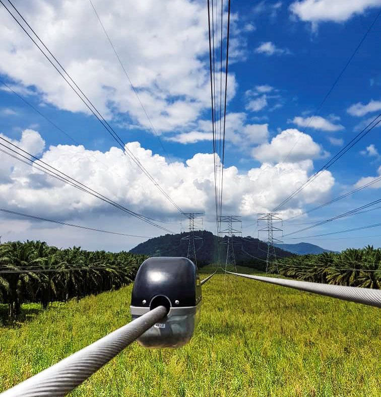
TLM® Transmission Line Conductor Monitor: MEASURE
SMARTLINE® requires real- me informa on regarding conductor behavior. The TLM conductor monitor
is an accurate, real- me, conductor clearance measurement device for use with the SMARTLINE
system. The Lindsey TLM Conductor Monitor provides a complete picture of conductor behavior
including actual conductor clearance-to-ground, conductor temperature, and line current. Unlike other
transmission line monitors that use other measurements to infer sag, the TLM monitor provides
accurate, ac onable, clearance-to-ground distance measurements. The TLM monitor is an easily
installed, self-powered conductor monitoring solu on for system voltages up to 765kV.

Conductor Clearance                                         Self-Powered, Simple Installation
The distance to ground from the conductor is                TLM Monitors are self-powered by line current as low as 50A.
measured using an on-board LIDAR sensor providing           Installa on can be accomplished quickly by using hot s ck,
a highly accurate line clearance measurement                helicopter, or bare hand prac ces. Lines do not have to be
regardless of tower or insulator mo on, varying span        de-energized for installa on. No modifica ons to transmission
lengths or other line condi ons. Mul ple TLM                towers or insulator/hardware assemblies are required.
monitors can also be used to ensure line clearance is       The TLM monitor is suitable for use on bundled conductors.
maintained to under-crossing lines.
                                                            Conductor Span Temperature
Line Current                                                Accurate conductor temperatures are important to develop
TLM monitors provide accurate line current                  accurate dynamic line ra ngs. No conductor models are required
measurements which are me-aligned with conductor            as SMARTLINE’s learning algorithms develop as-built models of
clearance measurements. TLM monitors can also be            conductor behavior for each monitored span. Combined with
used independently of SMARTLINE for                         direct distance to ground measurements, these models compute
stand-alone current monitoring applica ons.                 the averaged conductor temperature across the length of the
                                                            spans, regardless of any shielding effects caused by surrounding
                                                            terrain.

                                                        6
Choose from Cellular or Satellite Communications
TLM® monitors are available with either cellular or Iridium satellite communica on op ons. All monitors are
pre-configured to ensure hands-free communica on upon power-up.

Cellular Communications                                     Satellite Communications
For those who prefer cellular communica ons, TLM            Built-in Iridium satellite radio ensures reliable
monitors are available with a built-in global Tri-Band      communica ons in even the most remote loca ons
LTE-FDD and Dual-Band GPRS/EDGE modem which                 with no dependence on any other infrastructure.
supports LTE CAT-M/NB-IoT protocol. Lindsey                 Use of the Iridium satellite network requires no other
provided cellular phone service provides coverage           hardware to be installed on the line other than the
in most countries.                                          TLM monitors, and requires no other effort as is
                                                            typically associated with an RTU. TLM monitors
                                                            are factory configured for immediate connec on to the
                                                            Iridium network a er installa on on a transmission line.

                                                            Specifications
                                                            Parameter                       SpecificaƟon
                                                            Conductor current nominal       50 - 1500A
                                                            Conductor voltage               765kV L-L max
                                                            AC voltage frequency            50Hz - 60Hz
                                                            Conductor temperature           356°F (180°C) max
                                                            Conductor size                  Up to 1.8” (46mm)
                                                            Conductor type                  Aluminum or copper
                                                            Power on line current           80A
                                                            Minimum line current            50A
                                                            Tilt-pitch                      -90° to +90°
                                                            Angle-roll                      -90° to +90°
                                                            Height sensor distance          328 (100m) max
                                                            Height sensor accuracy          +/- 4” (+/- 100mm)
                                                            Opera ng ambient temperature    158°F (70°C) max
                                                                                            16.5” (L) x 6.75” (W) x 8.75” (H)
                                                            Dimensions
The TLM monitor uses built-in LiDAR to directly                                             (420mm x 170mm x 220mm)
measure the distance from the conductor to
the ground below. Compared to other methods                 Weight                          17 lbs (7.7kg)
that determine conductor sag, this method
accurately provides the actual electrical
clearance of the line.
Photo Courtesy of StatneƩ:
Pilot project in Norway

                                                           7
SMARTLINE-DLRTM Software: RATE
Dynamic Line Ra ng, or DLR, is a transmission line’s actual real- me power carrying capacity based on
real- me conductor and weather condi ons along with knowledge of conductor behavior.
A line’s DLR is typically 10 - 25% higher than a line’s sta c (or base) ra ng. This addi onal capacity is usually
available 95% of the me. DLR capacity provides opportuni es in economic dispatch, trading, opera ons,
and conges on mi ga on.

The Next Generation of DLR
                                                            DLR or AAR?
Dynamic line ra ngs must ensure a line’s electrical
                                                            Only DLR provides situational awareness
clearance-to-ground would not be violated if the
line was opera ng at its DLR value. The ra ng                                             Seasonally adjusted ra ngs
must also ensure the conductor does not                                                   (SAR) and ambient
overheat, which would result in thermal damage                                            adjusted ra ngs (AAR) are
and permanent weakening of the conductor.                                                 commonly used to increase
                                                                                          a line’s sta c ra ng. These
•   SMARTLINE-DLR uses con nuous line
                                                                                          techniques acknowledge
    clearance monitoring to ensure
                                                                                          different prevailing
    clearance-to-ground limits are not exceeded.
                                                            ambient temperature condi ons exist at different mes
•   SMARTLINE-DLR uses averaged conductor span              of the year. However, they ignore the impact of wind,
    temperatures to track the thermal performance of        which has a significantly greater impact on line ra ngs
    the line. Validated by direct temperature               than ambient temperature.
    measurements, the system ensures thermal limits
    are not exceeded.                                                                              Further, the
                                                                                                   recommenda on
•   Learning-based algorithms ac vely learn line
                                                                                                   that wind speed
    behavior, resul ng in much more accurate
                                                                                                   assump ons
    ra ngs than other methods. This technique
                                                                                                   should be
    properly reflects “as-built” line condi ons
                                                                                                   reduced when
    compared to using “as-designed”
                                                                                                   considering
    assump ons.
                                                            lower ambient temperatures* is usually ignored,
The combina on of learning-based conductor                  increasing the risk associated with AAR and SAR.
behavior models and direct measurements of
                                                            Dynamic line ra ng is a transmission line’s actual,
cri cal conductor parameters make
                                                            real- me, power carrying capacity. Using real- me
SMARTLINE-DLR line ra ngs unmatched.
                                                            measurements, DLR takes into account all weather
The advanced algorithms used by SMARTLINE-DLR               parameters including ambient temperature, wind
provides the core input to SMARTLINE-TCFTM                  speed, wind direc on, and solar radia on, as well as
which then develops forecast line ra ngs.                   actual line behavior, including clearance to ground and
                                                            conductor temperature. Dynamic line ra ng provides
                                                            the situa onal awareness of a line’s actual ra ng.

                                                            * “GUIDE FOR SELECTION OF WEATHER PARAMETERS FOR BARE
                                                            OVERHEAD CONDUCTOR RATINGS,” CIGRE, CIGRE and IEEE Joint
                                                            Task Force Working Group B2-12, August 2006, Sec on 1.5.3.1

                                                        8
SMARTLINE-TCFTM Software: FORECAST
SMARTLINE-TCF builds on the learned line behavior models and dynamic line ra ng capabili es of
SMARTLINE-DLRTM to develop highly accurate forecasts of transmission line power carrying capacity.

Firm, Fixed Forecasts                                Selective Data Presentation
Firm transmission line power capacity forecasts      SMARTLINE-TCF provides detailed interac ve graphic display
can be provided from 1-hour to seven days ahead.     for engineering analysis, simple numeric display for EMS
For example, a 2-hour forecast indicates the line    operator screen display, and flexible discrete data import
may be operated at the forecast level for the next   into EMS systems.
two hours, while a 24-hour forecast allows
opera on at the forecast level for the next
24 hours.

Flexible Forecast Scheduling
                                                          Why Transmission Line Capacity
Forecasts can be scheduled to be run once a day,
or updated periodically. For example, a                   Forecasting?
12-hour forecast could be run once at midnight            Forecasting is not the same as DLR
and then be updated hourly star ng at 8 am.
                                                          DLR is a transmission line’s real- me power
Forecast Bundles                                          carrying capacity. SMARTLINE-TCF builds on the
Sets of forecasts can be set to run on a regular          situa onal awareness provided by DLR and
basis. Define one set of forecasts to support the         provides stable forecasts of transmission line
day-ahead market, another for the real- me                power carrying capacity with a very high confidence
market, and another for transmission                      factor. Unlike the more variable nature of DLR,
engineering and planning departments.                     the stability and high confidence factors of these
                                                          forecast ra ngs make them suitable for a wide
High Confidence                                            range of opera onal applica ons.
By default, SMARTLINE-TCF forecasted ra ngs are           Numerous studies have shown this addi onal
set to ensure a 98% confidence factor is achieved         capacity provides opportuni es in economic
for the forecast ra ng. This means the                    dispatch, trading, opera ons, and conges on
instantaneous DLR during the forecast period has          mi ga on. Applica on of DLR and forecas ng are
only a 2% likelihood of being below the                   powerful tools for improving con ngency planning, cost
forecast ra ng for that moment in me.                     effec vely addressing lines with slow load growth,
If desired, higher or lower confidence factors may        and deferring or elimina ng the need for line
be used.                                                  upgrades or reconductoring.
Clearance Compliant
The use of real- me, LiDAR-based measurements
of conductor clearance-to-ground ensures forecast
ra ngs maintain compliance to clearance limits in
addi on to adhering to all conductor thermal
limits.

                                                      9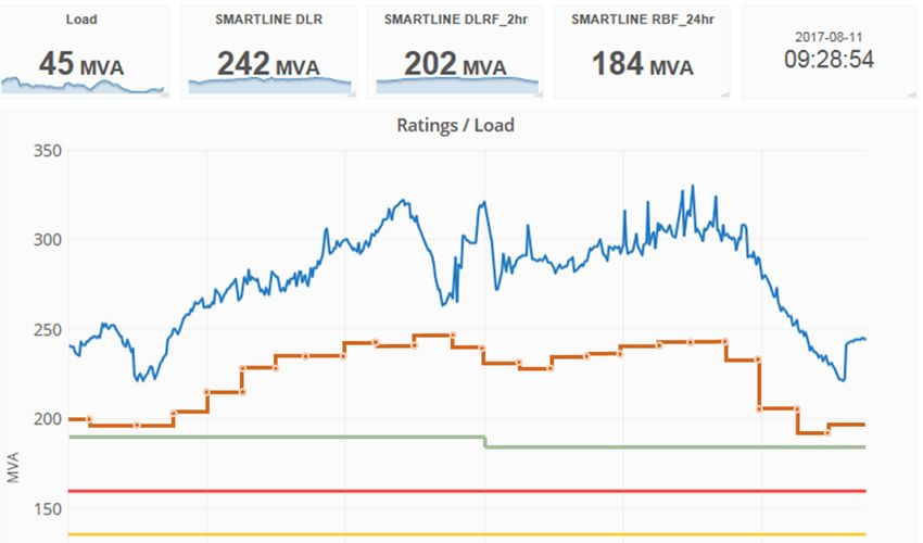
The SMARTLINE® Process

                Lindsey TLM® Conductor
                monitors provide direct
                measurement of conductor
                current, conductor spot
                temperature, ground
                temperature, and actual
                conductor-to-ground distance
                via built-in LiDAR. The la er
                eliminates the need for sag
                es ma ons and avoids issues
                associated with differences
                between plan profile drawings
                and actual as-built condi ons.
                                                  SMARTLINE-DLRTM is the underlying
                                                  DLR so ware that feeds SMARTLINE-
                                                  TCFTM. As-built conductor behavior
                                                  models are learned for each span
                                                  using real- me data and measured
                                                  parameters. Instantaneous DLR
                                                  ra ngs are developed using real- me
                                                  weather data and data computed
                                                  from the learned behavior models.
                                                  No assumed conductor models are
                                                  used, resul ng in consistent, less
                                                  sporadic ra ngs.

                                             10
The op onal asset monitoring The overall line forecast
module uses the learned is set at the lowest level
conductor behavior modeling forecast of all line
of SMARTLINE® to track the sec ons during the
effects of mechanical loading forecast window.
The SMARTLINE-TCFTM so ware develops
events on the conductor. This
future DLR ra ngs for the desired forecast
module provides a real- me
me-period based on forecasted weather
indica on of loss of strength
data. These are compared to the
based on conductor creep.
corresponding instantaneous DLR at the
forecasted me. Sta s cal analysis of the
results over me allows SMARTLINE-TCF to
generate forecasts with a 98% confidence
factor. Forecasts are generated for each
monitored line sec on.
11Conductor Asset Monitoring (Optional): MONITOR
Predic ng conductor lifecycle is a difficult task. O en, such analysis only takes place a er one or more failure
events on a transmission line. At this point, it is too late to avoid outages or to allow for proac ve capital
budge ng and project planning.
The op onal Conductor Asset Health module for SMARTLINE® system provides an accurate, live assessment of
conductor life. The learning-based conductor behavior model used by SMARTLINE allows the system to track
conductor life as a percentage of the conductor’s maximum lifecycle creep. The result is shown in an intui ve
bar graph for each monitored span.
Establishing a Baseline
SMARTLINE systems are generally installed
on exis ng lines, where years of opera onal
loading and exposure to the environment
has typically resulted in loss of conductor
strength. This loss of strength introduces
creep (or elonga on of the conductor) over
the conductor’s ini al “no creep” condi on.
During system set-up, Lindsey engineers will
analyze the line design including PLS-CADD
models and LiDAR scan data as available, to
determine the line’s final design creep level
and its ul mate design creep. The la er
typically reflec ng a 10% loss in strength.
However, SMARTLINE allows the user to
specify the residual strength criterion.
Dynamic Modeling
TLM® conductor monitors installed along the
line provide con nuous sensing of the
conductor’s behavior. Events that affect a
conductor’s life, such as galloping, major ice
loading, and wildfires, will be reflected by
changes in creep. The dynamic modeling
provided by SMARTLINE provides a reliable
indicator of where the conductor is along its
lifecycle. This mi gates risk by monitoring
Monitoring conductor life is vital for reliable system operaƟon.
conductors for op mal replacement while SMARTLINE’s Asset Health Module tracks the permanent elongaƟon of
maximizing the life of each conductor. conductors and the resulƟng loss of strength.
12Span L6-L7
TLM 0978i
Health %
0 10 20 30 40 50 60 70 80 90 100 110 120
% Lifecycle Conductor Creep
Ini al Design Final Design Real Time Replacement Creep
“No Creep” Creep In-Situ Creep (Predefined acceptable lifecycle
creep, e.g. 10% strength loss)
IntuiƟve Conductor Aging Indicator:
Conductor creep is the permanent elonga on a conductor experiences over its life and is related to loss
of strength. SMARTLINE® provides an intui ve display showing the current status of the conductor’s aging
process as related to conductor creep. As loading condi ons over the life of a transmission line will affect
each span differently, SMARTLINE provides this display for each monitored span.
1314
Data Security and Interfaces
SMARTLINE® is designed as a highly secure system that is easy to integrate into u lity applica ons, which
provides useful graphical tools for engineering analysis.
Cyber Security Graphical User Interface
• TLM® monitors are inherently cyber secure. • Graphical representa on of all line and weather data
Monitors are installed mid-span on the HV and forecasts are provided for engineering analysis. All
transmission line and are not accessible for data can be downloaded in convenient CSV or JSON
physical a ack as compared to RTUs, formats for off-line analysis.
ground-based or tower-based sensors, • View output by line or individual TLM monitor output.
and/or radios. View forecasts for each line sec on or for the overall
line.
Iridium-based TLM monitors have no
on-board communica on port or SIM card Application Programming Interface Included
and provide no terrestrial path to the
• SMARTLINE includes an easy to use applica on
data server.
programming interface (API) which allows for quick
Iridium based communica on is inherently integra on into EMS, asset management systems, and
secure due to its use of naturally short other cri cal applica ons.
messages, non-con nuous transmission,
• The interface has been designed as a RESTful API that
doppler frequency shi s and short beam
uses h ps requests to collect data using less bandwidth
handover me.
than other methods making it ideal for internet usage.
Cellular-based TLM monitors use TLS1.2
secret key encryp on algorithms to provide
end-point authen ca on and
communica on security over IP.
• Two-factor authen ca on ensures access is
granted only to the person authorized.
SMARTLINE provides for unlimited users.
• Regular penetra on tes ng assesses the
effec veness of SMARTLINE’s security
controls by simula ng real-world
cyber-a acks.
• All databases and so ware have full
redundant backup ensuring minimal The direct-to-satellite communicaƟons provided by Iridium-
based TLM monitors is ideal where exisƟng communicaƟons
disrup on in the event of failure.
infrastructure is either not available or less than ideal.
• Independent databases are maintained for all
customers ensuring no commingling of data.
15About Lindsey Systems
Lindsey Systems is recognized globally as an innovator in the electric power industry.
As a supplier of systems, products, and product solu ons for the transmission and
distribu on of electricity, Lindsey enables u li es to meet the challenges of the
modern-day electrical grid.
With over 70 years of experience and a reputa on as a thought leader in the industry,
Lindsey Systems’ products are known around the world for reliability and performance.
Lindsey is ISO-9001, ISO-14001 and CSA W47.2 Cer fied.
For more informa on, visit www.Lindsey-USA.com.
Thoughtful Solutions in Transmission Line Monitoring
Lindsey Manufacturing Co., dba Lindsey Systems
760 N. Georgia Avenue | Azusa, CA 91702 USA
Tel. +1-626-969-3471 | www.lindsey-usa.com
©2021 Lindsey Systems, Lindsey, SMARTLINE, SMARTLINE-DLR, SMARTLINE-TCF, and TLM
are trademarks or registered trademarks of Lindsey Manufacturing Co.
Iridium is a trademark of Iridium Communica ons Inc.
U.S. Patents 7,786,894 and 8,738,318 and other U.S. and foreign patents pending.
Publica on Number 11B-002 SMARTLINE-TCF • March 2021
16You can also read