PHYSICAL REVIEW RESEARCH 2, 013247 (2020) - Physical ...
←
→
Page content transcription
If your browser does not render page correctly, please read the page content below
PHYSICAL REVIEW RESEARCH 2, 013247 (2020)

            Scattering of Dirac electrons from a skyrmion: Emergence of robust skew scattering

                                     Cheng-Zhen Wang ,1 Hong-Ya Xu,1 and Ying-Cheng Lai                     1,2,*
               1
                   School of Electrical, Computer and Energy Engineering, Arizona State University, Tempe, Arizona 85287, USA
                                   2
                                     Department of Physics, Arizona State University, Tempe, Arizona 85287, USA

                                  (Received 20 November 2019; accepted 7 February 2020; published 3 March 2020)

                   We study electron scattering from a closed magnetic structure embedded in the top surface of a topological
                insulator. Outside the structure there is a uniform layer of ferromagnetic insulators, leading to a positive effective
                mass for the Dirac electrons. The mass inside the structure can be engineered to be negative, leading to a
                skyrmion structure. The geometric shape of the structure can be circular or deformed, leading to integrable or
                chaotic dynamics, respectively, in the classical limit. For a circular structure, the relativistic quantum scattering
                characteristics can be calculated analytically. For a deformed structure, we develop an efficient numerical
                method, the multiple-multipole method, to solve the scattering wave functions. We find that, for scattering
                from a skyrmion, an anomalous Hall effect, as characterized by strong skew scattering, can arise, which is
                robust against structural deformation due to the emergence of resonant modes. In the short- (long-)wavelength
                regime, the resonant modes manifest themselves as confined vortices (excited edge states). The origin of the
                resonant states is the spin phase factor of massive Dirac electrons at the skyrmion boundary. Further, in the
                short-wavelength regime, for a circular skyrmion, a large number of angular momentum channels contribute
                to the resonant modes. In this regime, in principle, classical dynamics is relevant, but we find that geometric
                deformations, even those as severe as leading to fully developed chaos, have little effect on the resonant modes.
                The vortex structure of the resonant states makes it possible to electrically charge the skyrmion, rendering
                feasible the electrical manipulation of its motion. In the long-wavelength regime, only the lowest angular
                momentum channels contribute to the resonant modes, making the skew scattering sharply directional. These
                phenomena can be exploited for applications in generating dynamic skyrmions for information storage and in
                Hall devices.

                DOI: 10.1103/PhysRevResearch.2.013247

                         I. INTRODUCTION                                     phase space. In this case, there is sensitive dependence on
                                                                             initial condition because two nearby trajectories will diverge
   This paper is devoted to studying relativistic quantum
                                                                             from each other exponentially, the hallmark of chaos. Since
scattering of Dirac electrons in systems involving magnetism.
                                                                             geometric deformations are inevitable in applications, it is
There are two motivations. First, quantum scattering of spin-
                                                                             necessary in the study of quantum scattering to take into
1/2 fermions is fundamental to developing two-dimensional
                                                                             account the nature of classical dynamics. In particular, it is
(2D) Dirac-material-based devices. Second, magnetic materi-
                                                                             useful to consider deformed domains to uncover the possible
als have been efficient carriers of information and the physics
                                                                             effects of classical chaos on quantum scattering.
of magnetic textures has been a topic of significant interest. In
                                                                                 We employ the setting of a 2D closed magnetic structure
general, in quantum scattering, the nature of the underlying
                                                                             embedded in a uniform layer of ferromagnetic insulator (FMI)
classical dynamics can play a role. For example, consider
                                                                             materials on the top of a 3D topological insulator (TI). Outside
electronic scattering from a 2D electrical potential domain
                                                                             the structure, due to the FMI layer and the proximity effect,
generated by an external gate voltage. In the classical limit
                                                                             the electrons obey the Dirac equation with a positive mass.
of zero wavelength, the electrons are point particles and the
                                                                             The mass of the closed structure can be engineered to be
domain is effectively a 2D billiard system in which electrons
                                                                             negative, making it a skyrmion [1–4]. The skyrmion structure
move along straight lines and are reflected when hitting the
                                                                             can be deformed so that the classical particle motion inside is
boundary. For a circular domain, the classical dynamics are
                                                                             chaotic. The massive Dirac electrons moving on the surface
integrable. However, for a deformed domain, e.g., a stadium-
                                                                             of the TI are scattered by the structure. The system thus not
shaped domain, the classical dynamics can be ergodic in the
                                                                             only provides a setting for exploring new physics associated
                                                                             with scattering of Dirac electrons from a magnetic skyrmion
                                                                             for applications, e.g., in spintronics, but also represents a
 *
     ying-cheng.lai@asu.edu                                                  paradigm to study the effects of classical chaos on relativistic
                                                                             quantum scattering in the presence of magnetism.
Published by the American Physical Society under the terms of the                To be systematic and general, we consider the cases where
Creative Commons Attribution 4.0 International license. Further              the magnetic structure on top of the TI can be of either
distribution of this work must maintain attribution to the author(s)         the skyrmion or the nonskyrmion type. The structure can
and the published article’s title, journal citation, and DOI.                simply be a circle, in which case the classical dynamics is

2643-1564/2020/2(1)/013247(13)                                  013247-1                              Published by the American Physical Society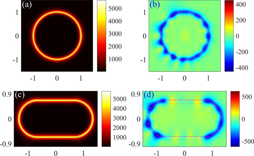
WANG, XU, AND LAI                                                                PHYSICAL REVIEW RESEARCH 2, 013247 (2020)

integrable, or it can be deformed from the circular shape,          of the competition between the Dzyaloshiskii-Moriya (DM)
e.g., a stadium, where there is fully developed chaos in the        interactions, Heisenberg exchange, and Zeeman interactions.
classical limit. For a circular structure, the various scattering   It has been demonstrated that metallic skyrmions can be
cross sections can be obtained analytically from the standard       driven by spin transfer torque from the electric current [7–9].
partial-wave analysis. For a deformed structure, we adopt an        Optical skyrmion lattices have been achieved in an evanescent
efficient method, the multiple multipole (MMP) method in            electromagnetic field [10]. In addition, the topological spin
optics, to solving the scattering wave functions of the two-        Hall effect has been demonstrated in which a pure trans-
component Dirac fermion in the magnetic system. We focus            verse spin current is generated from a skyrmion spin texture
on two regimes: the short-wavelength regime, where the size         [11–15].
of the magnetic structure is larger than the wavelength so that
the underlying classical dynamics is relevant, and the long-
wavelength regime, where the structure size is comparable to                           B. Topological insulators
or smaller than the wavelength. There are two main results.             Topological insulators are quantum materials with surface
First, a skyrmion can lead to strong skew scattering due to         states residing in the bulk insulating gap [16,17]. The edge
the emergence of resonant modes that manifest themselves as         states are topologically protected and are robust against non-
confined vortices inside the skyrmion in the short-wavelength       magnetic disorders due to a strong spin-momentum locking.
regime or confined edge states in the long-wavelength regime.       The electron motion on the surface follows the 2D linear
The resonant modes are the result of mass sign change across        dispersion with a single band-touching Dirac point and are
the skyrmion boundary. For a circular skyrmion, in the short-       described by the Dirac equation. In spite of the strong spin-
wavelength regime, a large number of angular momentum               momentum locking, the surface electronic states are sensi-
channels contribute to the resonant modes and electron charg-       tive to magnetic perturbations. That is, the electrons will
ing arises, providing a way to electrically manipulate the          be scattered off upon encountering a magnetic structure on
skyrmion motion. In the long-wavelength regime, only the            the surface of the TI. The interaction between the topolog-
lowest angular momentum channels contribute to the resonant         ical surface states and magnetic materials in a quasi-one-
states, leading to strongly directional skew scattering with        dimensional setting has been studied [18–20] where, due to
implications in developing Hall devices. The second result          the spin-momentum locking, the exchange coupling between
is that classical chaos generated by geometrical deformations       the magnetization and the surface electronic states can lead to
has little effect on the scattering from a skyrmion. The scat-      intriguing phenomena such as anomalous magnetoresistance
tering phenomena uncovered for the circular case are thus           and unconventional transport behaviors [21,22]. The interac-
robust. The immunity of the scattering dynamics to severe           tion can also lead to nonlinear or even chaotic dynamics in
deformation of the skyrmion structure is advantageous for           the evolution of magnetization of the FMI [23,24]. For exam-
spintronic device applications.                                     ple, complicated dynamics can emerge in the magnetization
    This paper is organized as follows. In Sec. II we provide the   switching due to a Hall-current-induced effective anisotropic
background of our research in terms of magnetic skyrmion,           field [18,25–27] and steady self-oscillations can arise in an
TIs, the marriage between the skyrmion and TI, and relativis-       FMI/TI heterostructure [28–30]. A quite recent computa-
tic quantum chaos. In Sec. III we describe the Hamiltonian          tional study has revealed phase locking in the magnetization
and outline the methods (analytic and numerical). In Sec. IV        dynamics of two FMIs on top of a 3D TI [31].
we demonstrate the emergence of robust resonant states in
scattering from the skyrmion for both integrable and chaotic
classical dynamics. In Sec. V we develop a partial-wave-                                 C. Skyrmion and TI
decomposition-based analysis for resonances associated with            Efforts in improving thermal efficiency and better ma-
scattering corresponding to classical integrable dynamics. In       nipulating skyrmions have led to the marriage between the
Sec. VI we summarize the main findings and discuss exper-           skyrmion and TI, where skyrmions arise on the surface of a
imental feasibility and open issues. Finally, in the Appendix       TI. Electric charging of magnetic vortices on the surface of
we detail the MMP method developed for numerically calcu-           a TI was investigated [32] and the confinement state in the
lating the scattering wave functions associated with deformed       skyrmion structure on the surface of a TI was discovered,
domain hosting chaotic dynamics in the classical limit.             paving the way to driving skyrmion motion using an applied
                                                                    electric field [33]. Electron skew scattering induced by the
                                                                    skyrmion structure on the TI surface was also studied [34].
                      II. BACKGROUND                                Quite recently, the combination of two skyrmions with op-
                                                                    posite winding numbers, called skyrmionium, in an FMI/TI
                    A. Magnetic skyrmion                            heterostructure was observed in the physical space [35–37].
   Generally, a skyrmion is a particlelike magnetic excitation      Theoretically, fluctuation-induced Néel and Bloch skyrmions
with a swirling topological 2D spin texture, i.e., the spin at      on the surface of a TI have been predicted [38].
the core and the spin at the perimeter point are in opposite           Previous studies focused on scattering of electrons from
directions [1–4]. The small size of the skyrmions and the           radially symmetric skyrmion structures. Deformed skyrmion
possibility of moving them with electrical currents of small        structure has been studied in recent years. For example, it was
density (∼105 A/m2 ) make them promising candidates for             found that Majorana modes are robust against skyrmion defor-
spintronic storage or logic devices [1,2]. Skyrmions have been      mations [39]. Quantum engineering of Majorana fermions in
experimentally observed in chiral magnets [5,6] as a result         a deformed skyrmion structure was also studied [40,41] and

                                                              013247-2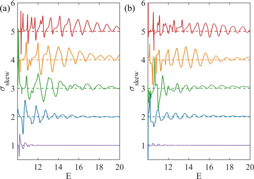
SCATTERING OF DIRAC ELECTRONS …                                                    PHYSICAL REVIEW RESEARCH 2, 013247 (2020)

deformed (elongated) skyrmions were used for stabilization
and control of Majorana bound states in proximity to an s-
wave superconductor [42]. Shape-dependent resonant modes
have been discovered recently in skyrmions in magnetic nan-
odisks [43].

                 D. Relativistic quantum chaos
    The study of the manifestations of classical chaos in
relativistic quantum systems was pioneered by Berry and
Mondragon [44] and recently emerged as an interdisciplinary
field of research [45,46] with applications to Dirac material
systems [47,48]. In contrast to the traditional field of (non-
relativistic) quantum chaos [49,50], where classical chaos
often bears strong signatures in the corresponding quantum               FIG. 1. Schematic illustration of electron scattering from a
systems, such identifying characteristics tend to be weakened        skyrmion structure in a thin FMI film deposited on top of a TI.
in the relativistic quantum counterparts [51,52]. For example,       (a) Band structure of the FMI/TI heterostructure. Outside (inside)
in scattering, e.g., electronic transport through a quantum-dot      the skyrmion structure, the mass corresponding to the band gap is
structure, chaos tends to smooth out fluctuations in scat-           positive (negative). (b) Illustration of electron scattering behavior
tering matrix elements, quantum transmission, or conduc-             from the skyrmion structure. The red (up) and blue (down) arrows
tance [53–58] if the quantum behaviors are governed by the           represent the magnetization vector n(r). For electronic states outside
Schrödinger equation. However, in 2D Dirac materials such as         and inside the skyrmion, the associated spin direction is different due
graphene, strong fluctuations of the quantum scattering char-        to the opposite signs of mass.
acteristics can persist to a certain extent in spite of classical
chaos [59,60]. Another example is a 2D deformed ring with            n can lead to an emergent magnetic field in the form
a line of magnetic flux through the center, where Schrödinger
electrons are localized but Dirac electrons can keep circulating                                     cdivn (r)
                                                                                            B(r) =               .
along the edges of the ring domain, generating a superper-                                             eh̄vF
sistent current in spite of fully developed classical chaos in
the domain [61], a phenomenon that can be exploited for              For a swirling skyrmion structure, the emergent magnetic field
creating a robust relativistic qubit [62]. Quite recently, the       B is zero and the in-plane component can be gauged away
weakening of the manifestations of chaos in spin-1/2 Dirac           [33,34]. In this case, the hard-wall approximation nz (r) = ±1
fermion systems was studied [52] using the approach of an            can be invoked [33,34], with the points inside and outside
out-of-time-ordered correlator [63]. It has also been revealed       the skyrmion structure taking on the value of minus one
that, for scattering in spin-1 Dirac-Weyl fermion systems, a         and one (n1 = 1 and n2 = −1), respectively. In experiments,
class of robust resonant modes can emerge that defy classical        such a structure can be realized using materials with a strong
chaos completely [51].                                               out-of-plane magnetic anisotropy. In our study, we assume
                                                                     that the magnetic structure is fixed and unaffected by the
                                                                     interface electrons. Experimentally, a skyrmion structure can
                 III. MODEL AND METHOD                               be stabilized via the DM interaction in the FMI [1,2], where
   We place an FMI thin film, e.g., Cu2 OSeO3 , on top of            the skyrmion size depends on materials parameters such as
a TI with a single magnetic structure at the center of the           the relative strength of the Heisenberg and DM exchange
thin film, as schematically illustrated in Fig. 1. The motion        interactions [1,2]. Our model is valid for skyrmions with a
of the surface electrons is affected by the structure with the       vortical magnetic texture as described. However, for hedgehog
magnetization vector n(r). The Hamiltonian of the system is          skyrmions, the in-plane magnetic field cannot be gauged away
                                                                     due to the emergent magnetic flux and the structure is not as
                H = vF ( p̂ × σ)z − s n(r) · σ,              (1)    stable as vortical skyrmions [1,2].
where vF is the Fermi velocity, p̂ = −i∇ is the momentum                The energy-momentum dispersion for electrons in free
operator, σ = (σx , σy , σz ) are the Pauli matrices, and s (> 0)   space with a uniform magnetic texture (constant mass) is
is the spin-splitting energy from the exchange interaction be-       given by
tween the electron and the magnetization. In polar coordinates
r = (r, θ ), for a circular structure, the magnetization vector                     E± = ± h̄2 vF2 kx2 + ky2 + 2 nz2 ,          (3)
can be parametrized as
                                                                   as shown in Fig. 1(a). While the energy dispersion curve in-
                                                                   side the skyrmion appears similar to that outside the skyrmion,
   n(r) = − sin θ 1 − nz2 (r), cos θ 1 − nz2 (r), nz (r) . (2)
                                                                     the spin direction is different for the electronic state due to the
For a deformed magnetic structure, there is swirling spin            opposite signs of mass. An electron will then go through a
texture with magnetic moment points up on the edge and               scattering process in this 2D system. Because of the breaking
down in the center [64]. The out-of-plane component of the           of the time-reversal symmetry, skew scattering will arise.
magnetic texture nz (r) acts as a Dirac mass term, which opens          For a circular magnetic structure, the scattering wave
a gap in the electronic band structure. The in-plane component       function and the related behavior can be solved analytically

                                                               013247-3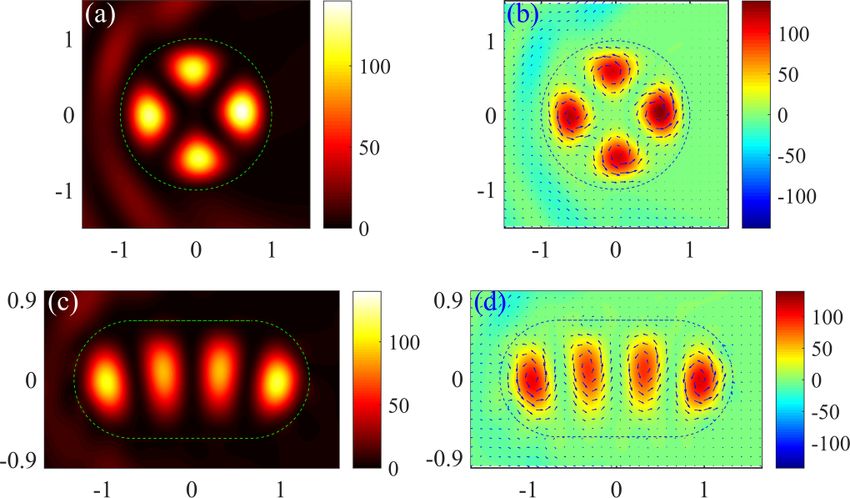
WANG, XU, AND LAI PHYSICAL REVIEW RESEARCH 2, 013247 (2020)
using the partial-wave-decomposition method (Sec. V). For a
deformed skyrmion, analytic solutions of the scattering wave
function are not feasible. We have developed an MMP-based
method, which has its origin in optics [65–69] and has recently
been extended to scattering of pseudospin-1 particles [51].
The basic idea is to assume two sets of fictitious poles along
and in the vicinity of the entire boundary of the magnetic
structure: one outside and another inside the boundary. Each
pole emits a wave in the form of a Hankel function (spherical
wave in the far field). The transmitted wave function at each
point inside the scatterer can be expressed as the superposi-
tion of the waves emitted by the poles outside the scatterer. FIG. 2. Skew scattering and transport cross sections versus inci-
Similarly, the refracted wave function at each point outside dent electron energy in the short-wavelength regime. (a) Skew scat-
the scatterer can be written as the combination of the waves tering cross section versus the energy. The red and blue curves cor-
emitted by the poles inside the scatterer. The incident plane respond to a circular and a stadium-shaped skyrmion, respectively.
wave and the reflected and transmitted waves are matched on The mass values are m1 = 10 and m2 = −10. (b) Backscattering
the boundary to enable the poles to be determined, and the cross section as a function of electron energy for the two skyrmion
expansion coefficients can be obtained by solving the matrix shapes as in (a). In each panel, the red curve has been shifted upward
eigenfunctions. (The details of the MMP method adopted by an amount specified by the horizontal red dashed line for better
for scattering from a magnetic structure are given in the visualization and comparison with the blue curve.
Appendix.) We validate the method by comparing the MMP
solutions with the analytic solution based on partial-wave terms outside and inside the magnetic structure, and f (θ )
expansion for a circular skyrmion. Overall, the MMP method denotes the 2D far-field scattering amplitude in the direction
is effective and efficient for solving both the near- and far-field defined by the angle θ with the x axis. For a circular structure,
scattering problem for a magnetic scatterer of arbitrary shape. f (θ ) can be obtained analytically. For a chaotic structure, once
In our calculation, we use the dimensionless quantity ob- the reflection function is calculated from the MMP method,
tained via consideration of the scales of the physical quan- f (θ ) can be obtained. The differential cross section is
tities involved. In particular, the energy scale in the FMI/TI
dσ
heterostructure is on the order of meV. In free space with zero = | f (θ )|2 . (5)
mass, the wave vector corresponding to the energy of 1 meV dθ
is k ∼ 1 meV/h̄vF = 3.04 × 10⁻³ nm−1 . We take the dimen- The transport and skew cross sections are defined, respec-
sionless radius of the magnetic structure (circular shape) to be tively, as
R = 1, which corresponds to a real structure of size of 100 nm. 2π
We then set the dimensionless energy corresponding to 1 meV σtr = dθ | f (θ )|2 (1 − cos θ ) (6)
to be kR = 0.304. For = 10, the corresponding energy gap 0
is 10/0.304 ≈ 33 meV. and
2π
IV. EMERGENCE OF ROBUST RESONANT STATES σskew = dθ | f (θ )|2 sin θ . (7)
0
IN SCATTERING FROM THE SKYRMION
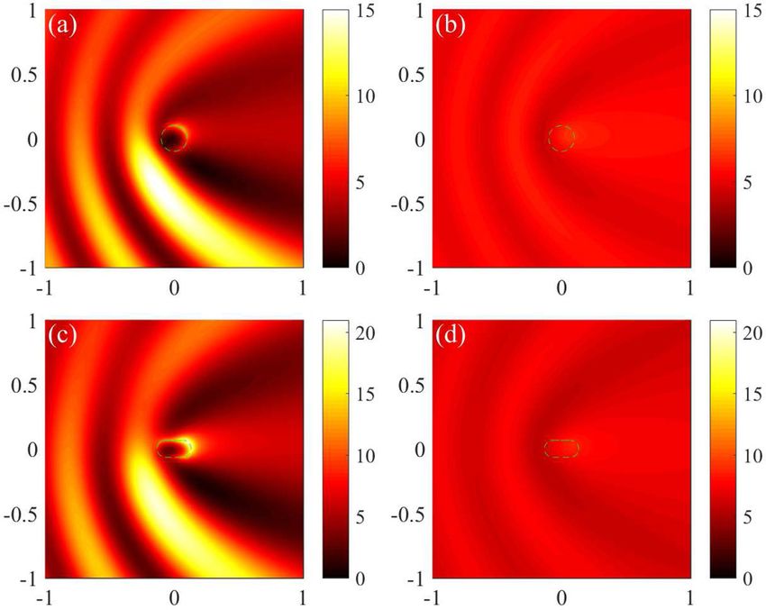
Figures 2(a) and 2(b) show, respectively, the skew scattering
A. Short-wavelength regime: Resonant vortices and edge modes and transport cross sections as a function of incident electron
We concentrate on a regime where the wavelength of energy, for a skyrmion (negative value of m2 ) of circular shape
the incoming Dirac electron is smaller than the size of the (upper panel) and stadium shape (lower panel) of the same
magnetic structure so that the classical dynamics inside the area π in dimensionless units. The stadium shape is chosen
structure is relevant. We consider a circular structure as well because of its mirror symmetry for the incident plane waves
as a deformed structure that leads to chaos in the classical so as to avoid an unnecessary complication: mixing of skew
limit to identify any effect of chaos on the electron scattering scattering and backscattering (or reflection). The aspect ratio
behavior. for the stadium shape is set to be 2. For both skyrmion shapes,
there are sharp resonant peaks in the skew cross section in
1. Far-field behavior the lower-energy range close to the gap, an indication of the
emergence of the anomalous Hall effect associated with Dirac
Far away from the scattering center, for unit incident
electron scattering from the skyrmion. As the incident energy
density the spinor wave function can be written as
is increased, the peak height is reduced but its width becomes
I = inc + ref larger, as a higher-energy value corresponds to less distortion
in the energy-momentum dispersion with the mass gap. Note
1 ikr cos θ
e−iθ f (θ ) ikr that there is little difference in the skew scattering cross-
≈ C h̄vF k e + C h̄vF k √ e , (4)
i E −m1 i E −m1 r section curves for the two skyrmion shapes, indicating that the
√ nature of the classical dynamics hardly affects the scattering.
where C is the normalization factor, k = kx2 + ky2 is the For the curves of the transport cross section, as shown in
electron wave vector, m1 = s n and m2 = s n are the mass Fig. 2(b), its value decreases with increasing energy. For
013247-4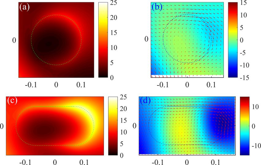
SCATTERING OF DIRAC ELECTRONS …                                                          PHYSICAL REVIEW RESEARCH 2, 013247 (2020)

    FIG. 3. Probability and current density distribution for selected
vortex states. (a) Probability distribution for scattering from a circu-       FIG. 4. Wave-function probability and current density distribu-
lar skyrmion for m1 = 10, m2 = −10, and E = 11.225. (b) In-plane           tion associated with selected edge states. (a) Probability distribution
current (marked by arrows) and spin-z component (color coded)              for scattering from a circular skyrmion for m1 = 10, m2 = −10, and
density distribution in the circular skyrmion region. (c) and (d) Cor-     E = 11.461. (b) Corresponding in-plane current (marked by arrows)
responding probability, current, and spin distribution for scattering      and spin-z component (represented by colors) density distribution.
from a stadium-shaped skyrmion for m1 = 10, m2 = −10, and E =              (c) and (d) Probability and spin distributions associated with scatter-
11.42.                                                                     ing from a stadium-shaped skyrmion for m1 = 10, m2 = −10, and
                                                                           E = 10.564.

low-energy values, the valleys in the transport cross section
correspond exactly to the skew scattering peaks. Sharp peaks               (color coded) in the 2D skyrmion structure, as shown in
also exist in the backscattering cross-section curve. Similar to           Figs. 3(b) and 3(d). We see that the confined resonant states
the skew cross section, the nature of the classical dynamics               form vortices with counterclockwise currents. There is also
has no appreciable effect. The results in Fig. 2 indicate that             an out-of-plane spin component along the positive z direction.
skyrmion skew scattering is robust against geometric defor-                The vortices have an apparent directionality, so they can affect
mations that are so severe as to change the classical behavior             the skew scattering direction and magnitude. The vortices
completely: from integrable dynamics to chaos.                             are formed by the interference of waves reflected from the
                                                                           boundary and are robust against boundary deformation. As
                       2. Near-field behavior                              a result, the nature of the classical dynamics, integrable or
   To understand the origin of the deformation- (chaos-)                   chaotic, has no significant effect on scattering.
independent far-field scattering (transport) behavior, we study               In addition to the confined vortex states inside the skyrmion
the near-field scattering behavior by examining the probability            structure, another form of confined states arises along the
density and the current density distribution associated with               skyrmion boundary, as shown in Figs. 4(a) and 4(c), for
some specific energy state. In particular, the probability                 scattering from a circular and a stadium-shaped skyrmion,
density is given by P =  † , where  = (ψ1 , ψ2 )T is the                respectively. There is strong confinement of the scattering
wave function, and the probability current operator is Jˆ =                wave function near the boundary with clockwise current and a
∇ p H = vF (σy , −σx ). The current density can be obtained as             spin-z component along the negative z axis direction, as shown
                                                                           in Figs. 4(b) and 4(d). The edge states correspond to sharp
           J = (Jx , Jy ) = vF [2(iψ1 ψ2∗ ), −2(ψ1 ψ2∗ )].          (8)    resonant peaks in the backscattering cross section marked by
The probability density distribution of the spin-z component               closed circles in Fig. 2(b). For the circular skyrmion, the edge
is given by                                                                states have no corresponding sharp peaks in skew scattering.
                                                                           For the stadium-shaped skyrmion, the edges states correspond
                       σz = |ψ1 |2 − |ψ2 |2 .                             to sharp valleys in the skew scattering cross section.
We choose a representative energy value corresponding to
a skew scattering cross section peak: E = 11.225 for the                             B. Long-wavelength regime: Resonant modes
circular skyrmion and E = 11.42 for the stadium-shaped                                          near the boundary
skyrmion, marked as the red and blue stars, respectively, in
Fig. 2(a). The probability and the current density distributions                                   1. Far-field behavior
are shown in Fig. 3. From both skyrmion structures, there are                 We consider the regime where the skyrmion size is smaller
scattering resonant states, as shown in Figs. 3(a) and 3(c).               than the electronic wavelength: R  1/k. This can be realized
The resonant patterns correspond to weak backscattering but                by setting the area of the skyrmion structure to be 0.01π
stronger skew scattering cross sections, indicating that these             for both circular (R = 0.1) and stadium-shaped skyrmions.
are effectively quasiconfined states. Further insights into the            In this long-wavelength regime, for a deformed skyrmion
contribution of the resonant states to skew scattering can be              structure, the MMP method is still effective for calculating
gained by examining the current density distribution (marked               the far-field cross sections and the near-field state distri-
by arrows) and the spin-z component density distribution                   bution. Representative results on the skew scattering and

                                                                     013247-5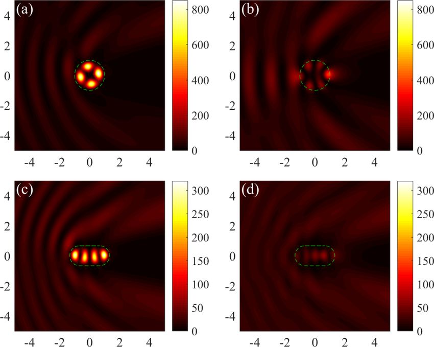
WANG, XU, AND LAI                                                                    PHYSICAL REVIEW RESEARCH 2, 013247 (2020)

   FIG. 5. Characteristics of Dirac electron scattering from a mag-
netic skyrmion in the long-wavelength regime. (a) Skew scattering
and (b) backscattering cross sections versus energy. The red and
blue curves correspond to a circular and a stadium-shaped skyrmion,
respectively. The mass values are m1 = 10 and m2 = −10. In each            FIG. 6. Wave-function probability and current density distribu-
panel, the red curve has been shifted upward for a proper amount for   tions for selected states for scattering in the long-wavelength regime.
better visualization and comparison with the blue curve.               (a) Probability distribution and (b) in-plane current together with the
                                                                       spin-z component density distributions, for scattering from a circular
                                                                       skyrmion for m1 = 10, m2 = −10, and E = 12.072. (c) and (d) Cor-
transport cross sections versus the incident energy are shown          responding results for scattering from a stadium-shaped skyrmion for
in Fig. 5. Different from the scattering behaviors in the short-       m1 = 10, m2 = −10, and E = 11.46.
wavelength regime, the oscillations of the skew scattering
cross section with energy are weak. For example, in the energy
range 10 < E < 20, only one smooth peak appears. There is              among the five cases, the resonant oscillations of the cross
hardly any difference in the scattering characteristics between        section with energy last longer for m2 = −9. On the contrary,
the two skyrmion structures, which is understandable as any            for m2 = 9 (nonskyrmion), the oscillations diminish rapidly
structural differences are not resolved in the long-wavelength         as the energy is increased. These behaviors hold regardless
regime. Because of a lack of appreciable oscillations, there is        of whether the underlying classical dynamics is integrable
directional skew scattering over a large energy range, a desired       or chaotic. Overall, a large difference between the masses
feature in Hall device applications.                                   inside and outside the magnetic structure can lead to stronger
                                                                       and long-lasting resonant modes and consequently to more
                      2. Near-field behavior                           pronounced skew scattering. Figures 8(a) and 8(b) show the
                                                                       probability density distribution for m2 = 9 and m2 = −9,
    We examine the state associated with the energy value
that leads to the lowest skew scattering cross section: E =
12.072 for the circular and E = 11.46 for the stadium-shaped
skyrmion; the respective probability density distributions are
shown in Figs. 6(a) and 6(c). The states are concentrated in
the vicinity of the boundary, which are different from the
vortex states observed in the short-wavelength regime. The
edge states thus represent a different type of resonant states
with directional current, as shown in Figs. 6(b) and 6(d). It
can be seen that the current direction is downward at the
edge, contributing to skew scattering. The spin-z component
is along the negative z direction.

      C. Further demonstration of strong skew scattering
                  from a skyrmion structure
    To further demonstrate the shape-independent skew scat-
tering behavior of Dirac electrons from a magnetic structure,
we study the effects of changing the mass of the skyrmion                  FIG. 7. Effects of varying mass on Dirac electron scattering in
texture. To be concrete, we set m1 > 0 and choose a set of pos-        the short-wavelength regime. The area of the magnetic structure is
itive and negative m2 values. In this setting, there is a skyrmion     π . (a) Skew scattering cross section versus the electron energy for a
for m2 < 0 but the magnetic structure is a nonskyrmion for             circular structure for mass values m2 = −9, −5, 0, 5, 9, represented
m2 > 0.                                                                by the red, orange, green, blue, and purple solid curves, respectively.
    We first examine the short-wavelength regime to probe into         In each panel, the curves have been shifted upward for better visual-
the origin of the emerged confined vortex states. Figures 7(a)         ization and comparison, where each horizontal dashed line denotes
and 7(b) show the skew scattering cross sections for the               the zero reference point. The mass outside the magnetic structure
circular and stadium-shaped magnetic structures, respectively,         is m1 = 10. (b) Corresponding curves for a stadium-shape structure
for m1 = 10 and m2 = −9, −5, 0, 5, 9. It can be seen that,             with the same mass values as in (a).

                                                                 013247-6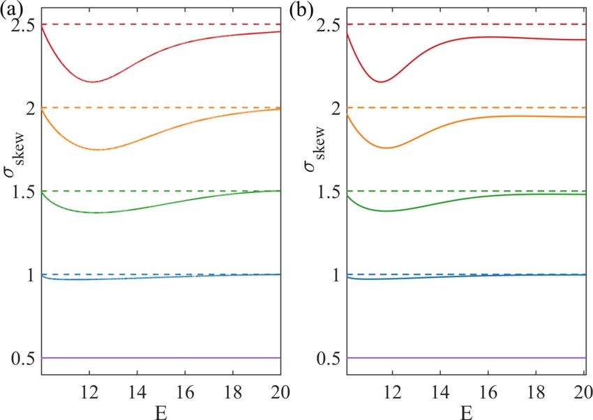
SCATTERING OF DIRAC ELECTRONS …                                                         PHYSICAL REVIEW RESEARCH 2, 013247 (2020)

                                                                              FIG. 9. Skew scattering for different mass values of the magnetic
                                                                          structure in the long-wavelength regime. The area of the structure is
    FIG. 8. Probability density distribution for selected states in the   π /100 and the mass outside the structure is m1 = 10. (a) For a circu-
circular and stadium-shaped structures for different masses in the        lar structure, skew scattering cross section for m2 = −9, −5, 0, 5, 9,
short-wavelength regime. (a) Circular skyrmion structure (m2 = −9)        represented by the red, orange, green, blue, and purple solid curves,
for E = 10.349, (b) circular nonskyrmion structure (m2 = 9) for E =       respectively. In each panel, the curves have been shifted upward for
10.234, (c) stadium-shaped skyrmion (m2 = −9) for E = 10.552,             better visualization and comparison, with the horizontal dashed lines
and (d) stadium-shaped structure (m2 = 9) for E = 10.514.                 denoting the zero reference point. (b) Corresponding results for a
                                                                          stadium-shaped magnetic structure.
respectively, for the circular magnetic structure. The corre-
sponding results for the stadium-shaped structure are shown               Because the circular and stadium-shaped skyrmion structures
in Figs. 8(c) and 8(d). For both structures, there are resonant           generate similar scattering behavior, the analytic results from
modes for m2 = −9 (when the magnetic structure is of the                  the circular skyrmion case also provides an understanding of
skyrmion type) but not for the case of m2 = 9.                            the emergence of strong skew scattering in the stadium-shaped
   In the long-wavelength regime, regardless of the shape of              skyrmion.
the magnetic structure (circular or stadium shaped), the skew                For a circular skyrmion, the rotational symmetry stipulates
scattering cross section decreases as the relative mass differ-           conservation of the total angular momentum Jˆz , [Jˆz , H] = 0,
ence is reduced, as shown in Fig. 9 for m2 = −9, −5, 0, 5, 9.
Figure 10 shows representative resonant states for the circular
and stadium-shaped structures for m2 = ±9. Again, when the
magnetic structure is of the skyrmion type, skew scattering is
strong, making the scattering electrons directional. However,
when the structure is not of the skyrmion type, skew scattering
is weak.

V. PARTIAL-WAVE-DECOMPOSITION-BASED ANALYSIS
   Numerically, we have observed strong skew scattering of
Dirac electrons from a skyrmion structure, which is robust
against geometric deformation. We now provide an analytic
understanding of skew scattering based on the method of
partial-wave decomposition. Consider a circular skyrmion.
Key to pronounced skew scattering is the resonant modes
emerged from the scattering process. In the short-wavelength
regime, a large number of angular momentum components
are involved in the scattering, leading to a large number
of resonant modes as the result of various combinations of                   FIG. 10. Probability density distribution for the states corre-
the angular momentum components, which are manifested                     sponding to the minimum of the skew scattering cross section
as peaks in the curve of the cross section with the en-                   in circular and stadium-shaped magnetic structures in the long-
ergy. In the long-wavelength regime, typically only a single              wavelength regime: (a) a circular skyrmion structure for m2 = −9
resonant mode is dominant, implying the involvement of                    and E = 12.152, (b) a circular nonskyrmion structure for m2 = 9 and
only the several lowest angular momentum components. The                  E = 12.317, (c) a stadium-shaped skyrmion structure for m2 = −9
asymmetric contribution from different angular momentum                   and E = 11.53, and (d) a stadium-shaped nonskyrmion structure for
channels leads to the observed pronounced skew scattering.                m2 = 9 and E = 11.72.

                                                                    013247-7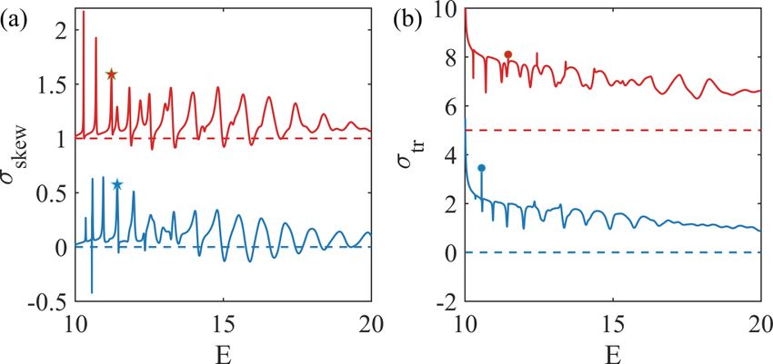
WANG, XU, AND LAI                                                                          PHYSICAL REVIEW RESEARCH 2, 013247 (2020)

and the partial-wave component with total angular momen-
tum j (= ±1/2, ±3/2, . . .) in polar coordinates (r, θ ) can be
written as
                                   u j (r)ei( j−1/2)θ
                    ψ j (r) =                         .               (9)
                                   v j (r)ei( j+1/2)θ
The Hamiltonian in the polar coordinates is

                  −  sn
                               −e −iθ ∂
                                      ∂r
                                           +  e−iθ i∂
   H = h̄vF iθ ∂ h̄vFiθ i∂              s n
                                                  r∂θ
                                                       .            (10)
             e ∂r + e r∂θ                h̄vF

Substituting the partial-wave form from Eq. (9) into the
Hamiltonian (10) leads to an eigenvalue problem and conse-
quently to the explicit expression for the partial waves.
   The transmitted wave inside the skyrmion structure (r < R)
can be expanded in terms of the partial waves as
                     ∞

                                   Jl−1 (k  r)ei(l−1)θ                          FIG. 11. Partial-wave-decomposition coefficients as a function
     ψ (r, θ ) = C
       T                   l−1
                          i Bl                              (11)
                   l=−∞
                                  − Eh̄vFk
                                             J (k  r)eilθ
                                      −s n l
                                                                             of total angular momentum for a circular magnetic structure in the
                                                                             short-wavelength regime. Among the quantities plotted, the Al ’s are
and the reflected wave outside the skyrmion (r > R) can be                   the coefficients for the reflected waves outside the structure and
written as                                                                   the Bl ’s are the transmitted wave coefficients. For a skyrmion struc-
                                                                           ture (m1 = 10 and m2 = −9), (a) |Al |2 and (b) |Bl |2 are plotted as a
                       ∞                       i(l−1)θ
                                    Hl−1  (kr)e                              function of j, where the corresponding state is shown in Fig. 8(a).
     ψ R (r, θ ) = C      il−1 Al                       , (12)               For a nonskyrmion structure (m1 = 10 and m2 = 9), (c) |Al |2 and
                                   − Eh̄vFk
                                            J (kr)eilθ
                                       −s n l
                     l=−∞                                                    (d) |Bl |2 are plotted versus j, where the corresponding state is shown
where C is a normalization factor and l = j + 1 = 2, Al and                  in Fig. 8(b).
Bl are the partial-wave expansion coefficients, Jl is the Bessel
function of the first kind, and Hl is the Hankel function of the             where
first kind of integer order l. We denote
                                        2 by         m1 =
                                                          s n(m2 =                                h̄vF k                  h̄vF k
s n ) the mass term and by k =
                                         E −2s n2
                                                     (k =
                                                            E 2 −2s n2
                                                                         )               τ =−             ,     τ = −              .
                                           h̄2 vF2              h̄2 vF2                          E − s n                E − s n
the wave vector outside (inside) the skyrmion structure. For
                                                                                 Using the explicit formulas for Al and Bl as given in
the incident electron in the free region outside the skyrmion
                                                                             Eqs. (17) and (18), respectively, we obtain the decomposition
structure, the wave function is
                                                                           coefficients versus the total angular momentum for R = 1.
                                  1                                          Figures 11(a) and 11(b) show, for the case of scattering
                   ψ =C
                      I
                                        eikr cos θ .                  (13)   from a skyrmion structure (m1 = 10 and m2 = −9), the ex-
                             i Eh̄vFk
                                 −s n                                       pansion coefficients versus the total angular momentum j.
Using the Jacobi-Anger identity                                              Figures 11(c) and 11(d) show the corresponding results for
                                                                             the nonskyrmion case (m1 = 10 and m2 = 9). It can be seen
                                    ∞
                                                                             that several angular momentum components contribute to the
                     eiz cos θ ≡          il Jl (z)eilθ ,           (14)     reflected wave component Al and the asymmetric distribution
                                   l=−∞                                      of the angular momentum components about zero leads to
we can expand the plane wave in the form                                     skew scattering. For the transmitted wave components, the
                                                                           distribution of the angular components is asymmetric as well,
                                       i(l−1)θ                               leading to the emergence of resonant vortices. For the Bl
                                J l−1 e
           ψI = C      il−1                        .                (15)     coefficients, their values for the nonskyrmion case are much
                     l
                             − Eh̄vFk
                                       J (kr)eilθ
                                 −s n l
                                                                             smaller than those for the skyrmion case, indicating that
Matching the waves at the skyrmion boundary (r = R)                          the skyrmion structure can confine the electrons much more
                                                                             effectively than the nonskyrmion structure.
                    ψ I (R) + ψ R (R) = ψ T (R),                    (16)         Setting R = 0.1 lands the scattering system in the long-
                                                                             wavelength regime. Figures 12(a) and 12(b) and Figs. 12(c)
we get, after some algebraic manipulation,
                                                                             and 12(d) show the coefficients associated with different
                 Jl−1 (kR)Jl (k  R) − ττ Jl (kR)Jl−1 (k  R)               angular momentum components for the skyrmion (m1 = 10
          Al =   τ                                                  (17)     and m2 = −9) and nonskyrmion (m1 = 10 and m2 = 9) cases,
                   H (kR)Jl−1 (k  R) − Hl−1 (kR)Jl (k  R)
                 τ l                                                        respectively. In both cases, only a single angular momentum
and                                                                          component contributes to the coefficient Al , i.e., j = −1/2,
               Jl−1 (kR)Hl (kR) − Jl (kR)Hl−1 (kR)                           giving rise to the directionality in the scattering and a slow
       Bl =                                               ,        (18)     change in the resonant cross section with the energy. The value
              Hl (kR)Jl−1 (k  R) − ττ Hl−1 (kR)Jl (k  R)                   of Al for the nonskyrmion case is much smaller than that of the

                                                                       013247-8
SCATTERING OF DIRAC ELECTRONS … PHYSICAL REVIEW RESEARCH 2, 013247 (2020)
general [51,52,59–61]. Second, strong skew scattering can
arise when the magnetic structure is a skyrmion, regardless of
the nature of the classical dynamics. In the short-wavelength
regime, the pronounced skew scattering is associated with
resonant modes manifested as confined vortices inside the
skyrmion structure, which are originated from the sign change
in the mass when the Dirac electrons travel from outside
to inside the skyrmion structure. A partial-wave analysis for
scattering from a circular skyrmion has revealed that a large
number of angular momentum channels contribute to the
resonant modes. We have also studied the long-wavelength
regime, where the geometric details of the magnetic structure
are unresolved, so naturally the scattering process is expected
to be independent of the nature of the classical dynamics. In
this regime, resonant states can still emerge as confined edge
states inside the magnetic structure, to which only a single
angular momentum channel contributes, leading to highly
FIG. 12. Transmitted and reflected partial-wave coefficients as directional skew scattering.
a function of the total angular momentum for a circular magnetic In the short-wavelength regime, the resonant states mani-
structure in the long-wavelength regime. The radius of the structure fested as confined vortices inside the skyrmion structure can
is R = 0.1. (a) |Al |2 and (b) |Bl |2 are plotted versus j for m1 = 10 be exploited for electrically charging the skyrmion structure
and m2 = −9 (skyrmion case), respectively, where the state is the [32,33], enabling the surface electrons on the TI to drive
one shown in Fig. 10(a). (c) |Al |2 and (d) |Bl |2 are plotted versus j skyrmion motion with a low current and high thermal effi-
for m1 = 10 and m2 = 9 (nonskyrmion case), respectively, where the ciency. In the long-wavelength regime, the strong and robust
corresponding state is shown in Fig. 10(b). directionality for skew scattering may be exploited for device
application based on the anomalous Hall effect.
skyrmion case. For the transmitted coefficient Bl , the angular Regarding experimental realization of a skyrmion struc-
momentum component j = −3/2 dominates the skyrmion ture, we note that there is recent evidence of a mag-
case and a number of components including j = −1/2 have netic skyrmion at the interface of the ferromagnet/TI
contributions in the nonskyrmion case, and the values of Bl (Cr 2 Te3 /Bi2 Te3 ) heterostructure [70]. In addition, inhomoge-
are much larger in the skyrmion case than in the nonskyrmion neous Zeeman coupling can be tuned for a ferromagnetic strip
case, again implying stronger confinement by resonance and with strong out-of-plane magnetic anisotropy [33]. For exper-
better directionality of scattering in the skyrmion structure as imental control of electron scattering over a skyrmion struc-
compared with those in the nonskyrmion structure. ture, a quantum-dot type of configuration with a skyrmion
structure in a finite scattering region as well as with leads and
contacts is necessary. The scattering configuration employed
VI. DISCUSSION
in our work is mainly for theoretical convenience with the goal
We have investigated relativistic quantum scattering of to gain insight into the physics of electron scattering over the
Dirac electrons from a closed magnetic structure embedded skyrmion structure with classical integrable or chaotic dynam-
in the top surface of a 3D TI. Outside the structure, there ics. For this purpose, the geometrical structure of the skyrmion
is a uniform FMI layer, leading to a finite but positive mass is chosen to be either circular, for which the scattering cross
for the Dirac electron. The mass of the structure itself can be sections can be calculated analytically, or deformed, for which
engineered to be negative or positive, where a skyrmion and the numerical method of multiple multipoles can be used to
a nonskyrmion structure arise in the former and latter cases, calculate the scattering wave function and consequently the
respectively. In the short-wavelength regime, the nature of the resonant states, cross sections, current, and spin distribution.
classical dynamics in the closed structure should be relevant to Our results provide useful hints about the scattering of spin-
the quantum scattering dynamics, according to conventional 1/2 fermion over a skyrmion structure. If the device size is
wisdom from the study of quantum chaos [49,50]. For a per- significantly larger than the electron wavelength, we expect
fectly circular structure, the classical dynamics is integrable. the main results to hold.
For a deformed structure such as one with the stadium shape, A number of open issues are worth studying, such as using
there is fully developed chaos in the classical dynamics. spin transfer torque of the electrons to drive the skyrmion mo-
We have two main findings. First, in the short-wavelength tion, exploitation of skyrmion-related switches or oscillators,
regime, classical chaos hardly has any effect on the scattering and scattering from multiple skyrmions that are themselves
dynamics. In fact, similar behaviors in the scattering charac- dynamic with possible phase-locking or antiphase-locking
teristics at a quantitative level, such as the skew scattering behavior.
and backscattering cross sections, arise for the circular and
stadium-shaped structures. The diminishing effects of classi-
ACKNOWLEDGMENTS
cal chaos on relativistic quantum scattering from a magnetic
structure are consistent with previous results on weakened This work was supported by the Pentagon Vannevar Bush
manifestations of chaos in relativistic quantum systems in Faculty Fellowship program sponsored by the Basic Research
013247-9WANG, XU, AND LAI PHYSICAL REVIEW RESEARCH 2, 013247 (2020)
Office of the Assistant Secretary of Defense for Research and ClmII are the expansion coefficients. The incident plane
and Engineering and funded by the Office of Naval Research wave propagating along the direction defined by an angle β
through Grant No. N00014-16-1-2828. with the x axis in region I is given by
ψ1in 1 1 i(kx r cos θ+ky r sin θ )
APPENDIX: MULTIPLE MULTIPOLE METHOD FOR in (r) ≡ =√ iβ e . (A3)
SCATTERING OF DIRAC ELECTRONS ON TOP OF A TI
ψ2in 2 −iτIe
FROM A MAGNETIC STRUCTURE Matching the boundary conditions
We denote the area outside and inside the skyrmion struc- I
ψ1 + ψ1in r j ∈ = ψ1II rj∈
, (A4)
ture as regions I and II, respectively (see Fig. 13). The wave
function in region II can be written as I
ψ2 + ψ2in r j ∈ = ψ2II , (A5)
rj∈
ψ1I ClmI Hl−1
(1)
(kII dmI )e−iθmI ilθm we get
(r) ≡
II
= √ e I,
ψ2II 2 τII Hl(1) (kII dmI )
mI l 1
(A1) ClmII √ τI Hl(1) kI r j − rmII eilθmII
mII l
2
where
1
− ClmI √ τII Hl(1) kII r j − rmI eilθmI
kII = E2 − 2 nII
2 /h̄v ,
F mI l
2
τII = −h̄vF kII /(E − nII ), i
= √ τI eiβ eikI r (A6)
dmI = r − rmI , 2
and
θmI = ϕ r − rmI ,
1 (1)
where φ(v) represents the angle of vector v, ClmI are the ClmII √ Hl−1 kI r j − rmII ei(l−1)θmII
expansion coefficients, and Hl(1) is the Hankel function of the mII l
2
first kind of order l. The scattered wave function in region I is 1 (1)
(1) − ClmI √ Hl−1 kII r j − rmI ei(l−1)θmI
−iθmII
ψ I
C mII
H (k I dm )e mI l
2
I (r) ≡ 1
= √l l−1 II
eilθmII ,
ψ2I 2 τI H (1)
(k I dm ) 1
mII l l II
= − √ τI eiβ eikI r , (A7)
(A2) 2
which can be cast in a compact form as
where
AlmII ClmII
j I
− AlmI ClmI
j II
= − j ψ2in , (A8)
kI = E − 2 nI2 /h̄vF ,
mII l mI l
τI = −h̄vF kI /(E − nI ),
BlmII ClmII
j I
− BlmI ClmI
j II
= − j ψ1in , (A9)
dmII = r − rmII , mII l mI l
θmII = ϕ r − rmII , where
1
j I
AlmII = √ τI Hl(1) kI r j − rmII eilθmII , (A10)
2
1
AlmI = √ τII Hl(1) kII r j − rmI eilθmI ,
j II
(A11)
2
1 (1)
BlmII = √ Hl−1
j I
kI r j − rmII ei(l−1)θmII , (A12)
2
1 (1)
BlmI = √ Hl−1
j II
kII r j − rmI ei(l−1)θmI (A13)
2
and
i
j
ψ2in = − √ τI eiβ eikI r j , (A14)
2
1
ψ1 = √ eikI r j .
j in
(A15)
2
FIG. 13. Schematic illustration of the basics of the MMP
method. The placement of poles (fictitious sources) is shown inside In principle, the set consists of an infinite number of equations
and outside a magnetic structure of arbitrary shape. The scattering with an infinite number of undetermined expansion coeffi-
spinor wave functions inside (outside) the structure are determined cients ClmII and ClmI . To solve the system numerically, finite
by the poles outside (inside) the structure. truncation is necessary. We set the total number of boundary
013247-10SCATTERING OF DIRAC ELECTRONS … PHYSICAL REVIEW RESEARCH 2, 013247 (2020)
points to be J with MI and MII poles in regions I and II, with
respectively, and l → [−L, L] for all the multipoles. The
process leads to the finite-dimensional matrix equation
⎛1 (τ ) (τ ) 1 (τ ) (τ ) (τ ) ⎞
M2J×N · CN×1 = −Y2J×1 , (A16) A−L1τ · · · 1Al1τ
Al2τ · · · 1AlM τ
· · · 1ALM τ
⎜2 (τ ) (τ ) ⎟
where N = (2L + 1) × (MI + MII ) = NI + NII , ⎜ A−L1τ (τ ) 2 (τ )
· · · 2Al1 (τ )
Al2τ · · · 2AlM · · · 2ALM ⎟
⎜ τ τ τ⎟
⎛ 1II ⎞ ⎜ . . .. .. .. ⎟
C−L ⎜ .. · · · .. . ··· ··· . ⎟
⎜ . ⎟
⎜ .. ⎟ A(τ ) = ⎜ j (τ ) ⎟,
⎜ . ⎟ ⎜ A−L1 · · · jAl1τ jAl2τ · · · jAlMτ · · · jALM) τ ⎟
(τ ) (τ ) (τ ) (τ
⎜ ⎟ ⎜ τ ⎟
⎜ C 1II ⎟ ⎜ . .. .. .. .. ⎟
⎜ l ⎟ ⎜ .. ··· . . ··· ··· . ⎟
⎜ 2II ⎟ ⎛ 1 in ⎞ ⎝ . ⎠
⎜ Cl ⎟ ψ2
⎜ ⎟ J (τ )
A−L1τ J (τ ) J (τ ) J (τ )
· · · Al1τ Al2τ · · · AlMτ · · · ALMτ J (τ )
⎜ .. ⎟ ⎜ .. ⎟
⎜ . ⎟ ⎜ . ⎟
⎜ M ⎟ ⎜ j in ⎟ (A19)
⎜C II ⎟ ⎜ ψ ⎟
⎜ l ⎟ ⎜ 2⎟ ⎛1 (τ ) (τ ) ⎞
⎜ . ⎟ ⎜ .. ⎟ B−L1τ (τ ) 1 (τ )
· · · 1Bl1 (τ )
Bl2τ · · · 1BlM · · · 1BLMτ
⎜ .. ⎟ ⎜ . ⎟
⎜ ⎟ ⎜ J in ⎟ ⎜2 (τ )
τ τ
(τ ) ⎟
⎜ MII ⎟ ⎜ ψ ⎟ ⎜ B−L1τ (τ ) 2 (τ )
· · · 2Bl1 (τ )
Bl2τ · · · 2BlM · · · 2BLM ⎟
⎜CL ⎟ ⎜ 2⎟ ⎜ τ τ τ⎟
⎜ ⎟ ⎜ ⎟ ⎜ . . .. .. .. ⎟
CN×1 = ⎜
⎜
⎟, Y2J×1 = ⎜
⎟ ⎜
⎟,
⎟ (A17) ⎜ ..
⎜ · · · .. . ··· . ··· . ⎟ ⎟
⎜ ⎟ ⎜ 1 in ⎟ B(τ ) = ⎜ j (τ ) ) ⎟.
⎜ 1I ⎟ ⎜ ψ1 ⎟ ⎜ B−L1 · · · Bl1τ Bl2τ · · · BlMτ · · · BLMτ ⎟
j (τ ) j (τ ) j (τ ) j (τ
⎜ C−L ⎟ ⎜ ⎟ ⎜ τ ⎟
⎜ ⎟ ⎜ .. ⎟ ⎜ . .. ⎟
⎜ .. ⎟ ⎜ . ⎟ ⎜ .. . .. ..
⎜ . ⎟ ⎜ j in ⎟ ⎝ · · · .. . ··· . ··· . ⎟⎠
⎜ 1I ⎟ ⎜ ψ ⎟
⎜C ⎟ ⎜ 1⎟ J (τ )
B−L1τ J (τ ) J (τ ) J (τ )
· · · Bl1τ Bl2τ · · · BlMτ · · · BLMτ J (τ )
⎜ l2 ⎟ ⎜ . ⎟
⎜C I ⎟ ⎝ .. ⎠
⎜ l ⎟ (A20)
⎜ . ⎟ ψ1 2J×1
J in
⎜ .. ⎟
⎜ ⎟
⎜C I ⎟
M
⎜ l ⎟
⎜ . ⎟ Here we denote τ = I (II ) and τ̄ = II (I ) the complement
⎝ .. ⎠
of τ . As the expansions are generally nonorthogonal, more
CLMI N×1
equations are required than the number of unknowns to enable
and reduction of an overdetermined matrix system with 2J N,
which can be solved by the pseudoinverse algorithm C =
A(I ) −A(II )
M2J×N = , (A18) −pinv(M) ∗ Y .
B(I ) −B(II )
[1] N. Nagaosa and Y. Tokura, Topological properties and dynam- [9] X. Yu, N. Kanazawa, W. Zhang, T. Nagai, T. Hara, K. Kimoto,
ics of magnetic skyrmions, Nat. Nanotech. 8, 899 (2013). Y. Matsui, Y. Onose, and Y. Tokura, Skyrmion flow near room
[2] A. Fert, V. Cros, and J. Sampaio, Skyrmions on the track, temperature in an ultralow current density, Nat. Commun. 3,
Nat. Nanotech. 8, 152 (2013). 988 (2012).
[3] K. Everschor-Sitte, J. Masell, R. M. Reeve, and M. Kläui, Per- [10] S. Tsesses, E. Ostrovsky, K. Cohen, B. Gjonaj, N. Lindner, and
spective: Magnetic skyrmions—Overview of recent progress G. Bartal, Optical skyrmion lattice in evanescent electromag-
in an active research field, J. Appl. Phys. 124, 240901 netic fields, Science 361, 993 (2018).
(2018). [11] G. Yin, Y. Liu, Y. Barlas, J. Zang, and R. K. Lake, Topological
[4] H. Ochoa and Y. Tserkovnyak, Quantum skyrmionics, Int. J. spin Hall effect resulting from magnetic skyrmions, Phys. Rev.
Mod. Phys. B 33, 1930005 (2019). B 92, 024411 (2015).
[5] S. Mühlbauer, B. Binz, F. Jonietz, C. Pfleiderer, A. Rosch, A. [12] K. S. Denisov, I. V. Rozhansky, N. S. Averkiev, and E.
Neubauer, R. Georgii, and P. Böni, Skyrmion lattice in a chiral Lähderanta, Electron Scattering on a Magnetic Skyrmion in
magnet, Science 323, 915 (2009). the Nonadiabatic Approximation, Phys. Rev. Lett. 117, 027202
[6] X. Yu, Y. Onose, N. Kanazawa, J. Park, J. Han, Y. Matsui, (2016).
N. Nagaosa, and Y. Tokura, Real-space observation of a [13] K. Denisov, I. Rozhansky, N. Averkiev, and E. Lähderanta, A
two-dimensional skyrmion crystal, Nature (London) 465, 901 nontrivial crossover in topological Hall effect regimes, Sci. Rep.
(2010). 7, 17204 (2017).
[7] F. Jonietz, S. Mühlbauer, C. Pfleiderer, A. Neubauer, W. [14] P. B. Ndiaye, C. A. Akosa, and A. Manchon, Topological Hall
Münzer, A. Bauer, T. Adams, R. Georgii, P. Böni, R. A. Duine and spin Hall effects in disordered skyrmionic textures, Phys.
et al., Spin transfer torques in MnSi at ultralow current densi- Rev. B 95, 064426 (2017).
ties, Science 330, 1648 (2010). [15] K. S. Denisov, I. V. Rozhansky, M. N. Potkina, I. S. Lobanov,
[8] J. Zang, M. Mostovoy, J. H. Han, and N. Nagaosa, Dynamics E. Lähderanta, and V. M. Uzdin, Topological Hall effect for
of Skyrmion Crystals in Metallic Thin Films, Phys. Rev. Lett. electron scattering on nanoscale skyrmions in external magnetic
107, 136804 (2011). field, Phys. Rev. B 98, 214407 (2018).
013247-11WANG, XU, AND LAI PHYSICAL REVIEW RESEARCH 2, 013247 (2020)
[16] M. Z. Hasan and C. L. Kane, Colloquium: Topological insula- [35] X. Zhang, J. Xia, Y. Zhou, D. Wang, X. Liu, W. Zhao, and M.
tors, Rev. Mod. Phys. 82, 3045 (2010). Ezawa, Control and manipulation of a magnetic skyrmionium
[17] X.-L. Qi and S.-C. Zhang, Topological insulators and supercon- in nanostructures, Phys. Rev. B 94, 094420 (2016).
ductors, Rev. Mod. Phys. 83, 1057 (2011). [36] O. V. Pylypovskyi, D. Makarov, V. P. Kravchuk, Y. Gaididei, A.
[18] Y. Tserkovnyak and D. Loss, Thin-Film Magnetization Dynam- Saxena, and D. D. Sheka, Chiral Skyrmion and Skyrmionium
ics on the Surface of a Topological Insulator, Phys. Rev. Lett. States Engineered by the Gradient of Curvature, Phys. Rev.
108, 187201 (2012). Appl. 10, 064057 (2018).
[19] P. Wei, F. Katmis, B. A. Assaf, H. Steinberg, P. Jarillo-Herrero, [37] B. Göbel, A. Schäffer, J. Berakdar, I. Mertig, and S. Parkin,
D. Heiman, and J. S. Moodera, Exchange-Coupling-Induced Electrical writing, deleting, reading, and moving of magnetic
Symmetry Breaking in Topological Insulators, Phys. Rev. Lett. skyrmioniums in a racetrack device, Sci. Rep. 9, 12119 (2019).
110, 186807 (2013). [38] F. S. Nogueira, I. Eremin, F. Katmis, J. S. Moodera, J. van den
[20] F. Katmis, V. Lauter, F. S. Nogueira, B. A. Assaf, M. E. Brink, and V. P. Kravchuk, Fluctuation-induced Néel and Bloch
Jamer, P. Wei, B. Satpati, J. W. Freeland, I. Eremin, D. Heiman skyrmions at topological insulator surfaces, Phys. Rev. B 98,
et al., A high-temperature ferromagnetic topological insulat- 060401(R) (2018).
ing phase by proximity coupling, Nature (London) 533, 513 [39] M. Garnier, A. Mesaros, and P. Simon, Topological supercon-
(2016). ductivity with deformable magnetic skyrmions, Commun. Phys.
[21] T. Yokoyama, Y. Tanaka, and N. Nagaosa, Anomalous mag- 2, 126 (2019).
netoresistance of a two-dimensional ferromagnet/ferromagnet [40] S. Rachel, E. Mascot, S. Cocklin, M. Vojta, and D. K. Morr,
junction on the surface of a topological insulator, Phys. Rev. B Quantized charge transport in chiral Majorana edge modes,
81, 121401(R) (2010). Phys. Rev. B 96, 205131 (2017).
[22] Z. Wu, F. M. Peeters, and K. Chang, Electron tunneling through [41] E. Mascot, S. Cocklin, S. Rachel, and D. K. Morr, Dimensional
double magnetic barriers on the surface of a topological insula- tuning of Majorana fermions and real space counting of the
tor, Phys. Rev. B 82, 115211 (2010). Chern number, Phys. Rev. B 100, 184510 (2019).
[23] G.-L. Wang, H.-Y. Xu, and Y.-C. Lai, Nonlinear dynam- [42] U. Güngördü, S. Sandhoefner, and A. A. Kovalev, Stabilization
ics induced anomalous Hall effect in topological insulators, and control of Majorana bound states with elongated skyrmions,
Sci. Rep. 6, 19803 (2016). Phys. Rev. B 97, 115136 (2018).
[24] G.-L. Wang, H.-Y. Xu, and Y.-C. Lai, Emergence, evolution, [43] Y. Liu, R. K. Lake, and J. Zang, Shape dependent resonant
and control of multistability in a hybrid topological quan- modes of skyrmions in magnetic nanodisks, J. Magn. Magn.
tum/classical system, Chaos 28, 033601 (2018). Mater. 455, 9 (2018).
[25] I. Garate and M. Franz, Inverse Spin-Galvanic Effect in the [44] M. V. Berry and R. J. Mondragon, Neutrino billiards: Time-
Interface between a Topological Insulator and a Ferromagnet, reversal symmetry-breaking without magnetic fields, Proc. R.
Phys. Rev. Lett. 104, 146802 (2010). Soc. London Ser. A 412, 53 (1987).
[26] T. Yokoyama, J. Zang, and N. Nagaosa, Theoretical study [45] Y.-C. Lai, H.-Y. Xu, L. Huang, and C. Grebogi, Relativistic
of the dynamics of magnetization on the topological surface, quantum chaos: An emergent interdisciplinary field, Chaos 28,
Phys. Rev. B 81, 241410(R) (2010). 052101 (2018).
[27] T. Yokoyama, Current-induced magnetization reversal on the [46] L. Huang, H.-Y. Xu, C. Grebogi, and Y.-C. Lai, Relativistic
surface of a topological insulator, Phys. Rev. B 84, 113407 quantum chaos, Phys. Rep. 753, 1 (2018).
(2011). [47] A. H. C. Neto and K. Novoselov, Two-dimensional crystals:
[28] Y. G. Semenov, X. Duan, and K. W. Kim, Voltage-driven Beyond graphene, Mater. Exp. 1, 10 (2011).
magnetic bifurcations in nanomagnet–topological insulator het- [48] P. Ajayan, P. Kim, and K. Banerjee, Two-dimensional van der
erostructures, Phys. Rev. B 89, 201405(R) (2014). Waals materials, Phys. Today 69(9), 38 (2016).
[29] X. Duan, X.-L. Li, Y. G. Semenov, and K. W. Kim, Nonlinear [49] H.-J. Stöckmann, Quantum Chaos: An Introduction (Cambridge
magnetic dynamics in a nanomagnet–topological insulator het- University Press, New York, 2006).
erostructure, Phys. Rev. B 92, 115429 (2015). [50] F. Haake, Quantum Signatures of Chaos, 3rd ed., Springer
[30] P. B. Ndiaye, C. A. Akosa, M. H. Fischer, A. Vaezi, E.-A. Kim, Series in Synergetics Vol. 54 (Springer, Berlin, 2010).
and A. Manchon, Dirac spin-orbit torques and charge pumping [51] H.-Y. Xu and Y.-C. Lai, Pseudospin-1 wave scattering that
at the surface of topological insulators, Phys. Rev. B 96, 014408 defies chaos Q-spoiling and Klein tunneling, Phys. Rev. B 99,
(2017). 235403 (2019).
[31] C.-Z. Wang, H.-Y. Xu, N. D. Rizzo, R. A. Kiehl, and Y.-C. Lai, [52] C.-D. Han, H.-Y. Xu, L. Huang, and Y.-C. Lai, Manifestations
Phase Locking of a Pair of Ferromagnetic Nano-Oscillators on of chaos in relativistic quantum systems—A study based on out-
a Topological Insulator, Phys. Rev. Appl. 10, 064003 (2018). of-time-order correlator, Phys. Open 1, 100001 (2019).
[32] K. Nomura and N. Nagaosa, Electric charging of magnetic [53] R. Blümel and U. Smilansky, Classical Irregular Scattering and
textures on the surface of a topological insulator, Phys. Rev. B Its Quantum-Mechanical Implications, Phys. Rev. Lett. 60, 477
82, 161401(R) (2010). (1988).
[33] H. M. Hurst, D. K. Efimkin, J. Zang, and V. Galitski, Charged [54] R. A. Jalabert, H. U. Baranger, and A. D. Stone, Conductance
skyrmions on the surface of a topological insulator, Phys. Rev. Fluctuations in the Ballistic Regime: A Probe of Quantum
B 91, 060401(R) (2015). Chaos? Phys. Rev. Lett. 65, 2442 (1990).
[34] Y. Araki and K. Nomura, Skyrmion-induced anomalous Hall [55] Y.-C. Lai, R. Blümel, E. Ott, and C. Grebogi, Quantum Man-
conductivity on topological insulator surfaces, Phys. Rev. B 96, ifestations of Chaotic Scattering, Phys. Rev. Lett. 68, 3491
165303 (2017). (1992).
013247-12You can also read