PILOT - Interstellar medium
←
→
Page content transcription
If your browser does not render page correctly, please read the page content below

PILOT
                                                                                  J-Ph. Bernard (IRAP, Toulouse)

                                                                                    On behalf of the PILOT team

                                                                         Pilot DPC Team: A. Mangilli (PostDoc), G. Foenard
                                                                         (PhD), A. Hughes, J. Aumont, I. Ristorcelli, L.
                                                                         Montier, H. Roussel, G. deGasperis, [B. Mot]
           1 000

                                                                                • PILOT
           300

                                                                                • Observations
Latitude
           0 000 0000

                                                                                • Data analysis current status

                                                                                • Preliminary polarization results
       0
       0
           30
           1 00

                        1 000   0 300   0 000 0000   359 300   359 000   1        J.-Ph. Bernard, ColdCore, Besançon, 4 June 2017
What do we know about dust polarization SED ?
We have very little constraints on the dust FIR polarized SED
despite the importance for dust models (and CMB foreground)

                                                             emission/extinction:
                                                             exceeds current
                                                             model predictions
                                                             by ~2.5
     Vaillancourt02
                                    Vaillancourt02

                                              Vaillancourt+08

                            Blast-pol
           Model                                             Planck
                        (Gandilo+16 VelaC)
      (Bethell+07 MC)                                        all sky at high |b|

                                       2        J.-Ph. Bernard, ColdCore, Besançon, 4 June 2017
What do we know about dust polarization SED ?
We have very little constraints on the dust FIR polarized SED despite
the importance for dust models (and CMB foreground)

                                                      Only 2 recent FIR measurements:
                                                      - Gandilo+16 (VelaC)
                                                      - Ashton+17 (VelaC)

                                                        Emission/extinction:
                                                        exceeds current
                                                        model predictions
                                                        by ~2.5
                          PILOT

                                     Guillet+2017

  Accurate FIR Measurements are desperately needed, sampling various
  environments from diffuse to dense and including external galaxies, …
  in particular to link alignment with dust optical properties
                                      3        J.-Ph. Bernard, ColdCore, Besançon, 4 June 2017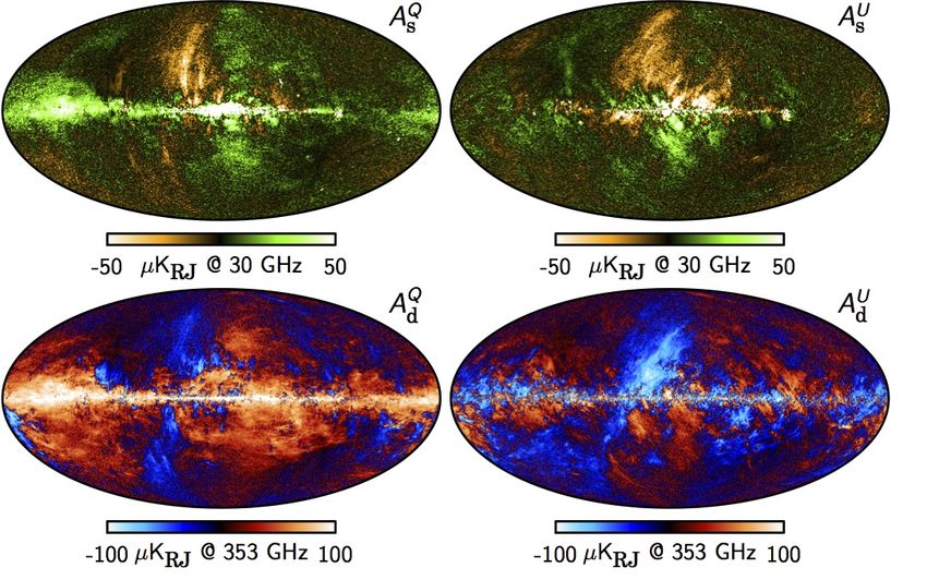
PILOT
Stratospheric balloon. Measurement of the polarized emission of
Fig. 15. the dust
Maximum in amplitude
posterior the inter galactic
polarization medium
maps derived from the at 1.2observations
Planck THz (far infra-red)
between 30 and 353 GHz
(Planck Collaboration X 2015). The left and right columns show the Stokes Q and U parameters, respectively. Rows show, from top
to bottom: CMB; synchrotron polarization at 30 GHz; and thermal dust polarization at 353 GHz. The CMB map has been highpass-
Participations: IRAP, IAS, CEA, CNES, Rome Univ., Cardiff Univ
filtered with a cosine-apodized filter between ` = 20 and 40, and the Galactic plane (defined by the 17 % CPM83 mask) has been
replaced with a constrained Gaussian realization (Planck Collaboration IX 2015).
Main scientific goals: Planck
• Reveal the structure of30the
Su
44
m
magnetic field sin
70 100 143 217 353 545 857
u t
our 30 44 70 100 143 217 353
RMS brightness temperature (µK)
RMS brightness temperature (µK)
al d
Galaxy and nearby galaxies:fg resolution 2’
Sy
rm
nc
e
2
2
h
10
10
T
hr
ot
ro
• Characterize the geometric and magnetic
n
CM
B
ld ust
rma
properties of the dust grains
1
1
10
10
Th e
Sum fg
• Understand polarized foregrounds Fr
ee
0
0
10
10
-fr CMB
Spin
CO 1-0
ee
• Complete the Planck observations at a higher
ning
Sy
nch
frequency where the dust polarization has never
dust
-1
-1
ro
10
10
tro
n
been observed10over large
30
sky regions
100 300 1000 10 30 100 300 1000
Frequency (GHz) Frequency (GHz)
Fig. 16. Brightness temperature rms as a function of frequency and astrophysical component for temperature (left) and polarization
Observation targets:
(right). For temperature, each component is smoothed to an angular resolution of 1 FWHM, and the lower and upper edges of each
line are defined by masks covering 81 and 93 % of the sky, respectively. For polarization, the corresponding smoothing scale is 400 ,
and the sky fractions are 73 and 93 %. • Galactic plane
10. Planck 2015 cosmology results • Star forming regions
lent agreement with this paradigm, and continue to tighten the
constraints on deviations and reduce the uncertainty on the key
Since their discovery, anisotropies in the CMB have contributed • Nearby galaxies
cosmological parameters.
significantly to defining our cosmological model and measuring The major methodological changes in the steps going
its key parameters. The standard model of cosmology is based
upon a spatially flat, expanding Universe whose dynamics are
• Faint regions (e.g. the BICEP2 field)
from sky maps to cosmological parameters are discussed
in Planck Collaboration XII (2015); Planck Collaboration XIII
governed by General Relativity and dominated by cold dark mat- (2015). These include the use of Planck polarization data in-
ter and a cosmological constant (⇤). The seeds of structure
4 have stead of WMAP,
J.-Ph. Bernard, changes to the foreground
ColdCore, Besançon, masks to include
4 June 2017
Gaussian statistics and form an almost scale-invariant spectrum more sky and dramatically reduce the number of point source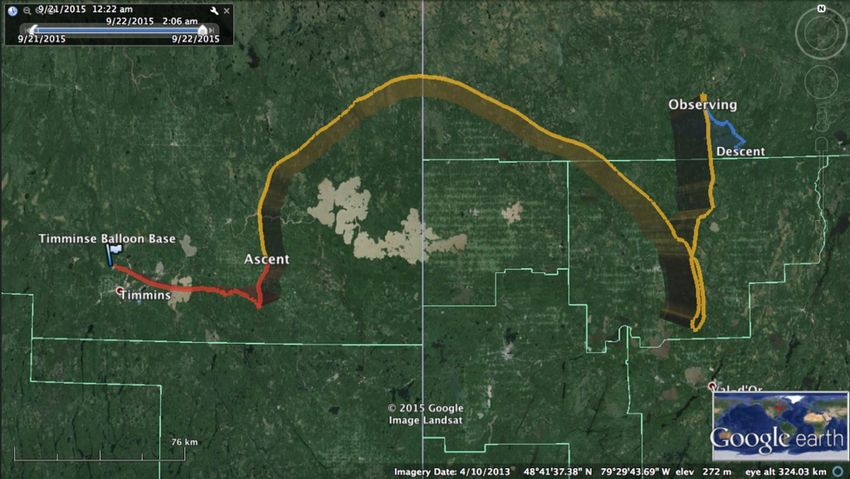
Polarization   measurement
         Description of the PILOT experiment
                  Description of the PILOT experiment

          where IwhereHWP
                     is  theI total
                               is theintensity,  Rxy is the
                                        total intensity,  Rxy detector    response,
                                                               is the detector              Table 1T
                                                                                     response,

                   1024 (750) bolometers
          Txy is the
                   Txyoptics
                        is thetransmission.     The ± is
                                optics transmission.     The−±andis +− for
                                                                        andTRANS
                                                                              + for TRANS   peraturep
          and REFLEX
                   and REFLEXarrays   respectively.
                                       arrays
                               REFLEX (-)
                                                     The
                                              respectively.additional
                                                              The       term
                                                                    additional O  term
                                                                                  xy  is O  is
                                                                                           xy isthe   to
                                                                                                       i
        4
          to account
             8
                        for a anfor
                   to account      arbitrary   electrical
                                       a an arbitrary      offset. offset.
                                                       electrical                           i, εi (ν )i
              For a perfect      HWP, βHWP,
                        For a perfect       = 0 and  =γ0=and
                                                  βPolarizer 0.5,γ =
                                                                   and0.5,
                                                                        thereandisthere
                                                                                    no is theno Plant
        3 term
             7 interm
                    2ω ininEqu.
                              2ω in8 which
                                       Equ. 8 simplifies   in
                                               which simplifies     in                      optical oe
                                                  TRANS (+)                                 and Ωi a
          m = RxymTxy =IR×xy[1Txy±I pcos2    cos4ωψ±
                                    × [1 ±ψpcos2        psin2
                                                      cos4        sin4ωψ] sin4
                                                            ω ±ψpsin2      + Oω  xy.] + Oxy.numbern
                                                                                   (9)      (9)
                                                                                            metric     c
                                                                                                       m
                                                            6    2
          In terms    of  the  Stokes
                   In terms 1024of the   parameters    as  defined   in  the  instru-
                                         Stokes parameters as defined in the instru-        S pix Ω i  =
                                                                                                       S
                                     (485) bolometers       5    1                          fective ft
          ment reference      frame, this
                   ment reference            equations
                                        frame,           writes
                                                this equations     writes
                                                                                            compute    c
          m = RxymTxy =×  Rxy
                            [IT±xyQcos4
                                  × [I ±ωQcos4     ω ±ωUsin4
                                             ± Usin4           ω.] + ONoise
                                                         ] + Oxy         xy.     (10) (10)
                                                                                                    F
                                                                                            Fτ (ν ) =
Observations at >2 different HWP angles to reconstruct Stokes parameters I, Q, U
         4.2     4.2 Photometric
             Photometric   Model Model
Wide FOV (about 1 sq. deg) unlike any other existing FIR polarized instrument
                                                                           τi (ν ) =
                 It is important
         It is important         to be
                         to be able    able5 to estimate
                                    to estimate   the        the optical
                                                    J.-Ph. Bernard,
                                                        optical     ColdCore,power
                                                                  power     falling  falling
                                                                              Besançon, 4 June 2017
                                                                                                 We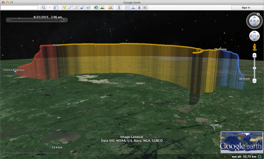
scanning strategy

        6     J.-Ph. Bernard, ColdCore, Besançon, 4 June 2017
The2 second
      x2      flight
                   68was made from34 the southern hemisphere in
                                                                                                 Flight#1 Timmins
the town of Alice Springs in the northern territories of Aus-
tralia. This launch was also carried out as part of a launch
                                                                             PILOT Flights
campaign led by CNES, and enabled the launch of the CLI-
 3.2 Second
MAT,    CARMEN Flightand PILOT experiments. The launch from
the southern hemisphere was the occasion to make observa-
   2 successful flights:
                                                                                                                      Ontario                   Quebec
 The second
tions          flight
       on objects   ofwas
                      the made   from the
                           skies which   aresouthern  hemisphere
                                             observable   only fromin
 the town
these       of Alice
       latitudes.     Springs
                   I will comeinback
                                   the northern  territories of later
                                       to these observations    Aus-
in     • 21 September 2015 Timmins Ontario (Canada)
 tralia. This launch was also carried out as part of a launch
   this section.
 campaign led by CNES, and enabled the launch of the CLI-                                               night: 5 hr                             day: 13.4
       • 16 April 2017 Alice Springs (Australia)
 MAT, CARMEN and PILOT experiments. The launch from
3.2.1 Improvements for Flight 2
 the southern hemisphere was the occasion to make observa-
 tions on objects of the skies which are observable only from                             Flight#1 Timmins, Canada
Between the first and second flights, improvements have been
 these latitudes. I will come back to these observations later
made to the instrument:
 in this section.
    FLIGHT1:                                                                                  Gondola  retrieval
                                                                                                  Ontario Quebec
– AnImprovements
3.2.1  attempt to repair    was performed
                       for Flight 2          on the matrices 1
     • Total flight time: 24 h
   and 3. As a result of this repair, only matrices 1 and                                     Avoided
                                                                                              night: 5 hr lakes …   day: 13.4 hr
   5 werethe
Between    dysfunctional    during
              first and second      ground
                               flights,     tests. All the
                                        improvements    haveother
                                                              been
   matrices  were operational. However, during the flight,
                                                                                                                            Total: 24 hr
made   • Total time at ceiling: 18.4 h
      to the instrument:

       • Ceiling altitude: 40 Km
  – An attempt to repair was performed on the matrices 1                           Sept 21 2016
    and 3. As a result of this repair, only matrices 1 and                                        Total: 24 hr
       • Scientific data: 14.8 h
    5 were dysfunctional during ground tests. All the other                        Timmins, Ontario,  Canada
                                                                                              but not forest …
    matrices were operational. However, during the flight,
                                                                                  Sept 21 2016
                                                                                  Timmins, Ontario, Canada
                                                                                                                                                                   Sc
                                                                                                                                                                   in
                                                                                                                                                                   bu
                                                                                                                                                                   re
                                                                                                             36              J.-Ph. Bernard, LLR, June 26 2017
                                                                                                                               36                                    J

Fig. 2: Evolution of the baffle from the begining of the day (top left) to
the end of the day (bottom right)                                                                                                     39                     J.-Ph. Ber
           Flight1 data accuracy affected by unexpected stray light due to baffle deterioration
                                                                                   7           J.-Ph. Bernard, ColdCore, Besançon, 4 June 2017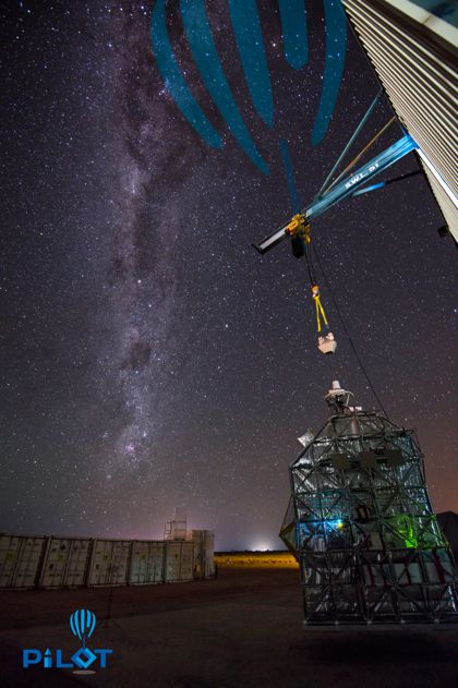
PILOT Flights
Flight#2: Alice Springs, Australia
April 16 2017                            FLIGHT2:
                                          Total flight time:       33.5 h
                                         April 16 2017
                                         Total   time     at ceiling:
                                         Alice-Springs Australia
                                                                       29.0 h
                                          Ceiling     altitude:
                                          • Total flight time: 33.532-40
                                                                    h     km
                                           • Ceiling altitude:
                                           Scientific     data:32-40 Km h
                                                                  23.8
                                     Gondola   retrieval
                                       • Scientific data: 23.8 h
                                     Instrument was recovered ~836 km East of Alice Springs
                                     Desertic area.          Perfect landing!       Gondola, back to Alice Springs

                                     landing area

 The PILOT team

                                     The
PILOT was recovered 836 km east   of Alice  Spring
                                     instrument       in a desert area
                                     looks ready to
                                     fly again !
                                                                         41
                                                                                          J.-Ph. Bernard, LLR, June 26 2017

                                            40 8          J.-Ph. Bernard, ColdCore, Besançon, 4 June 2017
                                                                       J.-Ph. Bernard, LLR, June 26 2017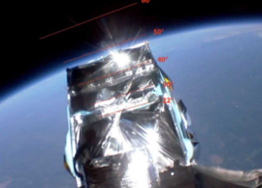
PILOT observations

        9     J.-Ph. Bernard, ColdCore, Besançon, 4 June 2017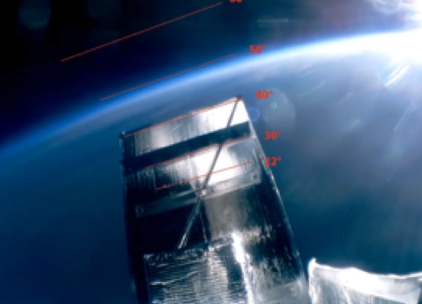
Flight2 observations

              -    Galactic plane: L0, L30 (1h30)
              -    Star forming regions:
                   Orion, Rho-Oph. , Musca (10h)
              -    Large Magellanic Cloud (6h)
              -    Diffuse region: BICEP field (5h)
              -    Planets: Saturn & Jupiter (1h)

                        Rho-Oph
                                   L0
                              L30 Musca
                                      LMC
                                                 Orion
                           BICEP

        10        J.-Ph. Bernard, ColdCore, Besançon, 4 June 2017
Flight2 improvements
rovements between
• Front baffle fixed: no more stray light
flights
• Lower focal plane temperature (flight1: 320 mK, flight2: 305 mK): 30% gain in time
• Longer flight (23.8hrs vs 14.8hrs of scientific observations)
or arrays repairs: -17%
• More bright sources: better pointing reconstruction
on atImproved
lower scanning
temperature: +26%
strategy with respect to Flight1
•
op size increased: (+10%)
- Observations are done at varying
affle fixed: no more straylight
elevation: instantaneous redundant scan
ficientangle + better constrain
observing of the
strategy
detector response map.
at varying elevation:
- Mapping limited to Region Of Interest,
directions allowing
scan angles and HWPde-stripping
positions
optimized mapping (+20%)
of interest
rong sources:
pointing reconstruction
flight (flight#1: 14.8hr, flight#2:1123.8 hr): +60%
J.-Ph. Bernard, ColdCore, Besançon, 4 June 2017Data Processing 12 J.-Ph. Bernard, ColdCore, Besançon, 4 June 2017
In-flight performances : Optics quality
Foenard, PhD thesis 2018
Foenard et al. 2018, Exp Astr, submitted
                                                                     Ground
                       In-flight Jupiter PSF

         • In-flight measured PSF on Jupiter is 2.2’ (expected 2’)
         • Ongoing investigations on temperature related effects
         • In-flight good optical quality and nominal resolution

                                                 13       J.-Ph. Bernard, ColdCore, Besançon, 4 June 2017
In-flight performances : instrumental Background
In-flight Background
Ground Background
• In-flight background has a similar shape but is a factor ~2 stronger than expected
• The background is polarized at 4-10% level. Origin not understood.
Unimportant for PILOT observations thanks to fixed HWP and Internal calibration but
important for some future applications.
• Dedicated observation to precisely measure instrumental background polarization,
atmospheric residual emission.
14 J.-Ph. Bernard, ColdCore, Besançon, 4 June 2017In-flight performances : Noise properties
Foenard, PhD thesis 2018
Foenard et al. 2018, Exp Astr, submitted
Noise Time-frequency plot over the whole flight (array#6)
frequency [Hz]
scan number
NEP [W/Hz^1/2]
- Noise is stable over the whole flight
- white noise level is as expected
- Slope: 1/f^0.6
frequency [Hz]
15 J.-Ph. Bernard, ColdCore, Besançon, 4 June 2017Data calibration
Foenard, PhD thesis 2018
Foenard et al. 2018, Exp Astr, submitted
• Temporal detector response variations: Internal Calibration Source (ICS)
Step-like variations due to Internal Calibration Source
- Array 6 Model
polarized background &
atmosphere variations
- Linear model parameters: HWP
position, elevation, altitude, optics
and structure temperatures
A simple model matches the variations
with accuracy (2%) over the whole flight
29 hrs
• Detector response spatial variations:
Atmosphere: extended and not
polarized is used to determine the
detector response flat-field.
16 J.-Ph. Bernard, ColdCore, Besançon, 4 June 2017time constants
Foenard, PhD thesis 2018
Foenard et al. 2018, Exp Astr, submitted
Time constants derived
from combination of :
- Glitches measuring
detectors τ with low SNR
- ICS raising curves
measuring detector + ICS
τ with high SNR
average τ = 0.7 sample
17 J.-Ph. Bernard, ColdCore, Besançon, 4 June 2017In-flight performances : Pointing accuracy
18 J.-Ph. Bernard, ColdCore, Besançon, 4 June 2017pointing
Herschel 250 mic PILOT 240 mic PILOT 240 mic - Estadius offset computed from
shifted
correlation with 250 μm
Herschel image of individual
observations
- Uses scanamorphos de-striped
maps of the PILOT data.
- Variations related to thermal and
mechanical deformations of the
instrument
- Modeled using linear regression
with temperature and elevation
19 J.-Ph. Bernard, ColdCore, Besançon, 4 June 2017pointing
Refined focal plane geometry
Elevation offset Same procedure on maps
from individual arrays ->
focal plane geometry
significant correction
wrt ground calibration
Cross-Elevation offset
accuracy ~2 arcsec
20 J.-Ph. Bernard, ColdCore, Besançon, 4 June 2017pointing
Refined focal plane geometry (Estadius rotation)
Using the size of the PSF on
compact sources, as a function of
rotation between Estadius and
PILOT, assumed when computing
bolometer coordinates
No significant deviation from 0°
detected.
Similar conclusion for individual
away rotation.
21 J.-Ph. Bernard, ColdCore, Besançon, 4 June 2017Summary of the current data analysis status
- Nominal noise levels, optical quality, angular resolution
- Data calibrated using responses derived from residual atmosphere signal and
calibration on the internal calibration Source
- The contribution from residual atmospheric emission subtracted using correlation
with pointing elevation
- Bolometer time constants derived using glitches and ICS. To be applied to data
- Pointing refined using bright sources
- Two pipelines for map-making: optimal map-maker (ROMAXPol [De Gasperis et al
2005] ) and a polarization destriper ( based on Scanamorphos [H. Roussel, 2013] )
22 J.-Ph. Bernard, ColdCore, Besançon, 4 June 2017Galactic center (L0)
PILOT P map PILOT expected
SNR p map
• 4 observations (~30min)
• Very bright : check data calibration,
detector responses and inter-
calibration
• Weakly polarized
ntensity maps
L30
L0 2° PILOT I map
• Best for galactic average average polarized SED
• yet, no extended measurements in the FIR
available.
• Magnetic nature of the twisted infinity loop ?
Orion 23 rho-Ophiuchi
J.-Ph. Bernard, ColdCore, Besançon, 4 June 2017Galactic center (L0)
ntensity maps
L30 450 mic
L0 2° polarization:
PILOT map Novak+03
850 mic
100 mic
polarization:
polarization:
Orion Chuss+03rho-Ophiuchi
Werner+88
PILOT beam
+ Planck …
Preliminary PILOT Intensity maps obtained
with Scanamorphos or simple map-makingPreliminary polarization maps of Galactic center
maps shown in EQU-IAU convention
at pixel size 1.7’ (Nside=2048)
Total Intensity polar Q polar U
PILOT DATA
preliminary polarization results Planck 850 mic in L0 field
maps shown in EQU-IAU convention
at pixel size 1.7’ (Nside=2048)
polar Q polar U
Simulated data (Planck) Total Intensity
25 J.-Ph. Bernard, ColdCore, Besançon, 4 June 2017Galactic center preliminary results
1 000
300
Latitude
0
0
0 000 0000
30
1 00
1 000 0 300 0 000 0000 359 300 359 000
Longitude
• Pilot analysis on the galactic center confirms good control of gain inter-calibration
• PILOT finds the orientation of the magnetic field along the galactic plane (and
Planck), in agreement with expectations
• We are working on characterization of uncertainties and filtering effects to de-bias
polarization fraction values
26 J.-Ph. Bernard, ColdCore, Besançon, 4 June 2017Polarization angles: PILOT vs Planck
- PILOT polarization angles are consistant with B field in the Galactic plane (polarization
angle=90°), which is expected statistically
- Agreement with Planck of the same order as the dispersion between Planck frequencies
- Remaining differences could have multiple origins: true rotation with frequency, remaining
defects in PILOT data, bandpass mismatch in Planck, etc
27 J.-Ph. Bernard, ColdCore, Besançon, 4 June 2017Perspectives
L30
L30 Orion LMC ridge
rho-Ophiuchi
- Improve / secure data processing pipeline (refine
rho-Ophiuchi pointing, effect of cross-talk, time constants)
rho-Ophiuchi - Uncertainties
Preliminary estimates
PILOT Intensity in map-making
maps obtained
with- Scanamorphos or simple
Publish Galactic map-making
center region results
- Engage similar analysis of other regions (L30, Orion,
rho-Ophiuchi, Musca, LMC)
- Statistical determination in Bicep2 (expect SNR~16)
- Flight3: Re-proposed in 2018 for 2019.
Northern sky, including M31, M33, galactic fan region.
Could include dedicated Cold Core
targets if sufficient interest
28 J.-Ph. Bernard, ColdCore, Besançon, 4 June 2017The PILOT team is small and opened to new collaborations …
The only requirement is to
participate to data processing
Journal Pilote
29 J.-Ph. Bernard, ColdCore, Besançon, 4 June 2017PILOT Spin offs
SPICA-Pol
IDS
coPILOT
- IDS (Inflation and Dust Surveyor): CMB Bmodes + dust proposed to NASA
2018. Contribution to provide Pilot Estadius + ICS.
- CoPilot: modification of PILOT will allow very accurate measurements of C+
(158 mic) total intensity. Dark molecular gas distribution in solar neighborhood,
nearby galaxies. Submitted to CNES in 2017, 2018.
- SPICA-pol: Polarized instrument on SPICA. Design and science case strongly
inspired from PILOT. Accepted in pre-phaseA/0.
Boost proposal (IRAP) to lower detector temperature to 150 mK.
Increase in sensitivity by 2.7 for PILOT, up to 14 for CoPilot
30 J.-Ph. Bernard, ColdCore, Besançon, 4 June 201731 J.-Ph. Bernard, ColdCore, Besançon, 4 June 2017
Conclusions
•   PILOT had a very successful Flight2
•   In-flight nominal performances and good data quality
•   Preliminary polarization maps of Galactic center produced after only 6 months
•   Maps show that weak polarization is successfully detected
•   Polarization direction consistent with expectations and with that by Planck
•   Pilot will constrain the polarization SED of the inner MW for the first time
•   Ongoing work to improve the data analysis pipeline and map quality
•   Results will be extended to a variety of MW regions: MW Plane, star forming
    regions, cold cores.
•   Will derive FIR polarization fraction and statistical properties of LMC, Bicep2.
•   Goals of Flight3 : nearby spiral galaxies M31, M33 + translucent clouds (Polaris) +
    high p translucent Planck regions + Cold Cores
          [The PILOT Collaboration, Bernard et al., Experimental Astronomy, 2016]
          [The PILOT Collaboration, Mikawa et al., Experimental Astronomy, 2016]
          [The PILOT Collaboration, Foenard et al., ‘In-flight performances’, In prep.]
                                                   32         J.-Ph. Bernard, ColdCore, Besançon, 4 June 2017
Very long duration flights ?
BlastPol-TNG visibility based on 28 days at South pole
PILOT Flight#2 targets
L30
rho-oph
L0
Bicep2 LMC Musca
The drawback of very long flight from South pole is
the very limited sky fraction that can be observed
33 J.-Ph. Bernard, ColdCore, Besançon, 4 June 2017Residual polarization
Residual polarization on an unpolarized planet mesures the data calibration accuracy
preliminary polarization results Jupiter, not destriped
PILOT Intensity map
of Jupiter
2’
Residual polarization on an unpolarized planet measure
the response accuracy
The residual polarization measured through
The residual aperture photometry
polarization measured on Jupiteraperture
through is
ΔP/I ~ 3% photometry on Jupiter is ΔP/I=3%
Significant improvement expected, more detailed calibration analysis on-going
34 J.-Ph. Bernard, ColdCore, Besançon, 4 June 2017You can also read