Prediction of forming effects in UD-NCF by macroscopic forming simulation - Capabilities and limitations
←
→
Page content transcription
If your browser does not render page correctly, please read the page content below
Conference Paper, Published Version

Kärger, Luise; Galkin, Siegfried; Kunze, Eckart; Gude, Maik; Schäfer,
Bastian
Prediction of forming effects in UD-NCF by macroscopic
forming simulation – Capabilities and limitations

Verfügbar unter/Available at: https://hdl.handle.net/20.500.11970/107674

Vorgeschlagene Zitierweise/Suggested citation:
Kärger, Luise; Galkin, Siegfried; Kunze, Eckart; Gude, Maik; Schäfer, Bastian (2021):
Prediction of forming effects in UD-NCF by macroscopic forming simulation – Capabilities
and limitations. In: Proceedings of the 24th International Conference on Material Forming:
ESAFORM 2021. Liege: ULiège Library. S. 355/1-355/11.
https://doi.org/10.25518/esaform21.355.

Standardnutzungsbedingungen/Terms of Use:

Die Dokumente in HENRY stehen unter der Creative Commons Lizenz CC BY 4.0, sofern keine abweichenden
Nutzungsbedingungen getroffen wurden. Damit ist sowohl die kommerzielle Nutzung als auch das Teilen, die
Weiterbearbeitung und Speicherung erlaubt. Das Verwenden und das Bearbeiten stehen unter der Bedingung der
Namensnennung. Im Einzelfall kann eine restriktivere Lizenz gelten; dann gelten abweichend von den obigen
Nutzungsbedingungen die in der dort genannten Lizenz gewährten Nutzungsrechte.
Documents in HENRY are made available under the Creative Commons License CC BY 4.0, if no other license is
applicable. Under CC BY 4.0 commercial use and sharing, remixing, transforming, and building upon the material
of the work is permitted. In some cases a different, more restrictive license may apply; if applicable the terms of
the restrictive license will be binding.

ESAFORM 2021. MS02 (Composite), 10.25518/esaform21.355

 Pr
 Prediction
 ediction of fforming
 orming eff
 effects
 ects in UD-NCF b
 byy macr
 macroscopic
 oscopic fforming
 orming simulation –
 Capabilities and limitations
 Luise Kärger, Siegfried Galkin, Eckart Kunze, Maik Gude and Bastian Schäfer

 Luise Kärger. Karlsruhe Institute of Technology (KIT), Institute of Vehicle System Technology (FAST), Karlsruhe, Germany
 Corresponding author: luise.kaerger@kit.edu
 Siegfried Galkin. Karlsruhe Institute of Technology (KIT), Institute of Vehicle System Technology (FAST), Karlsruhe, Germany
 Federal Waterways Engineering and Research Institute (BAW), Karlsruhe, Germany
 Eckart Kunze. Technical University Dresden, Institute of Lightweight Engineering and Polymer Technology (ILK), Dresden,
 Germany
 Maik Gude. Technical University Dresden, Institute of Lightweight Engineering and Polymer Technology (ILK), Dresden, Germany
 Bastian Schäfer. Karlsruhe Institute of Technology (KIT), Institute of Vehicle System Technology (FAST), Karlsruhe, Germany

 Abstr
 bstract
 act.. Unidirectional non-crimp fabrics (UD-NCF) provide the highest lightweight potential among dry
 textile materials. Compared to multiaxial NCF, the fabric layers in UD-NCF enable a more targeted tailoring.
 Compared to woven fabrics, the fibres of UD-NCF are straight without weakening undulations. However, the
 formability of UD-NCF is more challenging compared to woven fabrics. The yarns are bonded by a stitching
 and the deformation behaviour highly depends on this stitching and on the slippage between the stitching
 and the fibre yarns. Moreover, distinct local draping effects occur, like gapping and fibre waviness, which can
 have a considerable impact on the mechanical performance. Such local effects are particularly challenging or
 even impossible to be predicted by macroscopic forming simulation. The present work applies a previously
 published macroscopic UD-NCF modelling approach to perform numerical forming analyses and evaluate the
 prediction accuracy of forming effects. In addition to fibre orientations and shear angles, as investigated in
 previous work, the present work also provides indication for fibre area ratios, gapping, transverse compaction
 and fibre waviness. Moreover, the prediction accuracy is validated by comparison with experimental tests,
 where full-field strains of inner plies are captured by prior application of dots onto the fibre yarns, by
 measuring them via radiography and applying a photogrammetry software. The modelling approach provides
 good prediction accuracy for fibre orientations, shear strains and fibre area ratio. Conversely, normal fibre
 strains, indicating fibre waviness, and transverse strains, indicating gapping, show some deviations due to the
 multiscale nature of UD-NCF that cannot be captured entirely on macroscopic scale.

 Keyw
 ywor
 ords
 ds. Non-orthogonal Material Modelling, Non-crimp Fabrics, Draping Effects, Gapping, Waviness

1 Intr
 Introduction
 oduction
Non-crimp fabrics (NCF) provide an exceptionally high lightweight potential due to their straight fibres, compared
to undulated fibres in woven fabrics. Among NCFs, unidirectional (UD) NCFs enable a more targeted tailoring than
biaxial NCFs. However, their formability is much more challenging in comparison to bidirectional fabrics, and draping
effects like shearing, waviness or fibre gapping have a significant impact on the structural performance [1]-[3].
The experimental determination of those effects especially in inner layers of a multi-ply component is challenging
and requires dedicated measurement methods [4]. Draping simulations can more easily provide the necessary local
information, however need to be suitable and reliable. Mallach et al. [5] conducted optical robot-based measurements
of preforming tests to determine shear angles and fibre orientations on the entire surface. They compared the
measurements to a macroscopic approach with built-in methods in PAM-FORM and achieved a good prediction of the
preform contour and critical regions regarding wrinkling. However, mesoscopic effects like transverse compression,
fibre sliding and yarn buckling were not considered in their approach, which led to highly overestimated shear angles
as well as large deviations of the fibre orientation.

 355/1
Prediction of forming effects in UD-NCF by macroscopic forming simulation – Capabilitie...

Macroscopic approaches can predict component forming results efficiently for complexly curved geometries with
case-specific process conditions. Due to their better formability, woven fabrics have so far been the focus of research
on macroscopic forming models [6]-[8]. In contrast, forming of Biaxial-NCF [9], [10] or even UD-NCF [5], [11]-[14]
has been investigated much less and mostly based on mesoscopic approaches, which are not suitable for component
forming simulations. In contrast to mesoscopic modelling, macroscopic approaches are not able to discretely predict
local forming effects. Nevertheless, they need to capture the relevant forming mechanisms occurring on meso-scale in
a homogenized way and consequently indicate areas with a high likelihood of local effects like waviness, transverse
compaction or gapping [15]. This desired capability of macroscopic forming simulation of UD-NCF has not yet been
addressed in the literature. According to the current state of research and to the authors’ knowledge, the modelling
approach proposed by Schirmaier et al. [11] is the most promising macroscopic UD-NCF model available to date.
It considers both large-strain deformation and non-linear constitutive behaviour. To account for the permanent
deformation caused by irreversible slip between fibre yarns, stitching and glass fibres, an elastic-plastic material
model is chosen to capture the experimentally observed non-linearity of the macroscopic stress-strain relation [11],
[13], [16].

In previous work, the prediction accuracy of Schirmaier’s model was shown only by qualitative comparison to
component forming results [11], without full-field quantitative validation nor evaluation of specific forming effects.
Therefore, the model is applied in the present work to forming of an L-shaped geometry in order to quantitatively
evaluate the prediction quality regarding global and local forming effects. The results are compared to radiography
measurements of internal plies based on the method presented in Kunze et al. [4]. The measurement method allows
for the determination of the local deformation, which gives a direct measure not only for fibre orientations, but
also for forming effects like gapping, waviness and transverse compression, enabling an estimation, e.g., of the local
fibre volume content [17]. Subsequently, the suitability of the macroscopic approach to predict these local effects is
evaluated.

2 Macr
 Macroscopic
 oscopic fforming
 orming simulation of UD-NCF
The yarns of non-crimp fabrics (NCF) are bonded together by a stitching pattern and glass fibres for handleability.
This is in contrast to woven fabrics, which are intrinsically cohesive due to the interwoven fibre yarns. Consequently,
the inherent deformation modes of the two types of textiles differ considerably. Woven fabrics deform in pure shear,
while shear in UD-NCF can be superimposed by substantial transverse strain [12], [16]. This superposed membrane
behaviour needs to be captured by macroscopic material models in a suitable way. In previous work [11], extensive
off-axis-tension (OAT) tests have been performed to analyse the multiaxial deformations at meso and macro scale, and
to develop a macroscopic material model for the membrane behaviour. This macroscopic model is shortly presented in
the following section and is subsequently applied to investigate the prediction of forming effects.

2.1 Non-orthogonal elastic-plastic mat
 material
 erial model
Macroscopic modelling approaches account for material inhomogeneities in a homogenized way to allow an efficient
description of the most relevant deformation mechanisms. The utilized membrane modelling [11] is able to capture
large shear strains 12 superimposed with large non-orthogonal transverse tensile strains 2 and orthogonal
compressive strains ⊥, cf. Fig. 1(a). Tensile strains 2 (elongated stitching) and compressive strains ⊥ (transverse
compaction) may occur simultaneously, particularly for large shear strains 12. The macroscopic approach, however,
does not allow for a discrete modelling of the slipping between carbon fibre tows, glass fibres and stitching. Therefore,
gapping can only be indicated by large tensile strain 2 at moderate shear strain 12 or, more suitably, by large
transverse tensile strains ⊥.

 355/2
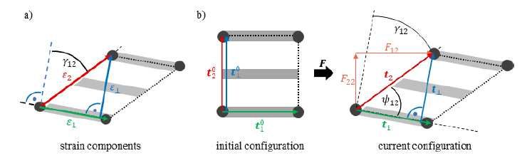
ESAFORM 2021. MS02 (Composite), 10.25518/esaform21.355

Modelling large non-orthogonal and non-linear deformation of the stitching requires suitable strain and stress
measures. For UD-NCF, Schirmaier et al. [11] proposed a formulation for appropriate linear strain and corresponding
nominal stress measures. Line segment 10 represents the material’s first principal direction, oriented in fibre
direction. Line segment 20 corresponds to the direction of the stitching, cf. Fig. 1(b). After deformation, the linear but
non-orthogonal strain components 1 of the fibres and 2 of the stitching are defined by:

where the line segments = ∙ 0 of the current configuration result from the deformation gradient . The shear angle
 12 is calculated by:

Additionally, the linear perpendicular strain component ⊥ is introduced based on the line segment ⊥ perpendicular
to 1:

cf. Fig. 1(a) [11].

 Fig. 1. (a) T
 Trrans
 ansvverse str
 strain
 ain 2 versus perpendicular str
 strain
 ain ⊥; (b) def
 deformation
 ormation of line segments 1, 2 and ⊥ , based
 on [11], [15]

In the corresponding alternative intermediate configuration, the nominal stress tensor ̲∗ can be formulated based on
an orthogonal material stiffness matrix by:

 355/3
Prediction of forming effects in UD-NCF by macroscopic forming simulation – Capabilitie...

accounting for large shear strains 12 and the non-orthogonal linear strains 1, 2. In this intermediate configuration,
the line segments remain in their initial orientation, elongated to the current configuration, based on an alternative
decomposition of the deformation gradient described in [11].

To account for elastic-plastic behaviour, the total tensile strain 2 and the total shear angle 12 are composed of elastic
as well as hardening plastic parts [11]. A yield condition defines the transition from elastic to plastic domain. Material
parameter fitting led to the conclusion, that in case of tensile loading of the stitching, the respective yield surface
 2Γ( 2, , 12) depends on the plastic strain 2, as well as on the shear angle 12, while in case of shear loading the yield
curve 12Γ( 12, ) only depends on the plastic shear 12, .

Transverse compression can only be transmitted perpendicular to the carbon fibres. This compressive stress ⊥
is modelled via a superimposed nonlinear elastic material law depending on ⊥ and 12 to account for the fact
that macroscopic wrinkling starts at higher in-plane transverse compression in case of high shear angles [11]. If
perpendicular strain ⊥ and transverse strain 2 have equal sign, disjunction needs to be ensured. Therefore, the
transverse stress 22∗ is set to zero for 20. A more detailed
description of the non-orthogonal-plastic UD-NCF membrane model is given in [11]. The model parameters for shear
and transverse tension have been identified based on experimental off-axis tension (OAT) tests of UD-NCF with three
different fibre orientations ={30°,45°,60°} [11], [17].

The bending behaviour of UD-NCF is modelled by a hypoelastic approach, initially introduced for thermoplastic UD-
tapes [18]. Bending stiffness stays orthogonal in case of large shear deformation and only requires an accurate rotation
of the unidirectional carbon fibres (line segment 1). The behaviour is assumed to be linear elastic and is defined by
the bending stiffness in fibre direction ||B and negligible stiffness perpendicular ⊥B to the fibres.

2.2 F
 Forming
 orming simulation model
The forming simulation model is implemented in ABAQUS. Since the high membrane stiffness in fibre direction is
combined with a very low bending stiffness, the deformation behaviour cannot be captured by conventional shell
theories based on Cauchy mechanics. Therefore, membrane and bending behaviour is modelled by superimposed
finite membrane and plate elements. The non-orthogonal elastic-plastic material model of the membrane behaviour
is implemented in a VUMAT subroutine [11]. For the plate element, a user-defined shell section integration is
implemented in a VUGENS subroutine [18]. The interface behaviour between the individual plies as well as between
tool and plies is modelled by combined normal and tangential contact, depending on normal pressure, slip-rate and
adhesion [18]. The contact model is implemented in a VUINTERACTION subroutine.

2.3 Pr
 Prediction
 ediction of fforming
 orming eff
 effects
 ects
Forming of UD-NCF is largely determined by the low shear and low transverse stiffness that highly depend on the type
of stitching and on the slippage between stitching and fibre yarns. The fibre orientation of the current configuration 1=
 ∙ 10 is computed by the initial fibre orientations 10 and the deformation gradient . The shear angle 12 results from

 355/4
ESAFORM 2021. MS02 (Composite), 10.25518/esaform21.355 Eq. (2). Transverse tensile or compressive deformation leads to gapping between fibre yarns or transverse compaction, respectively. Furthermore, mesoscopic buckling of the fibre yarns may occur due to lateral contraction of the stitching [16]. Assuming a constant fabric weight, the fibre volume content (FVC) depends on the initial FVC 0 and on the ratio between the initial area 0 and the deformed area In addition to fibre orientation, shear angle and FVC, the modelling approach provides indication to analyse three further forming effects: gapping, transverse compaction and fibre waviness [15], [17]. Thereby, observations based on extensive OAT tests have shown, that the non-orthogonal tensile strain component 2 (stitching) is not suitable for indicating gapping nor transverse in-plane compressive behaviour. Component forming simulations have shown that the perpendicular strain component ⊥ is more suitable for that purpose, to indicate, where gapping corresponds to tensile strains and compaction to compressive strains [11]. Fibre waviness occurs at meso scale and cannot be captured macroscopically. Such undulations typically arise in regions with compressive fibre strain, 1
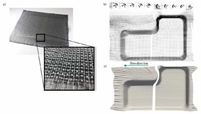
Prediction of forming effects in UD-NCF by macroscopic forming simulation – Capabilitie...

 Fig. 2. (a) L-shaped geometry
 geometry.. (b) F
 Forming
 orming ttool
 ool with 19 contr
 controllable
 ollable blank holders and L-shaped neg
 negati
 ativve mould. (c)
 Top and bott
 bottom
 om view of a UD-NCF pr
 pref
 eform
 orm with 8 la
 layyers Zolt
 Zoltek
 ek P
 PX35
 X35 and with a rred
 ed dot grid print
 printed
 ed on ttop
 op la
 layyer [4]

To analyse the resulting fibre orientations and the extent of forming effects in inner layers, a contrast-enhancing ink
used in X-rays is printed in a dot pattern on the fibre bundles (Fig. 3a) and is evaluated by radiography images [4].
To analyse outer plies, the method can also be applied with simple coloured points and a photo camera, cf. Fig 2c
(top). In this way, the deformation of individual fabric plies can be quantified locally, which gives a direct measure
for the fibre orientation as well as for forming effects like gapping and transverse compression, and thus enables an
estimation of the local fibre volume content [17]. Based on the measurements, a comparison with forming simulation
can be conducted by exporting the coordinates of the acquired 3D points and computing the deformation gradient in
relation to the reference state. Thus, a high-resolution quantification of the forming effects becomes feasible for inner
plies, cf. Fig. 3.

 355/6
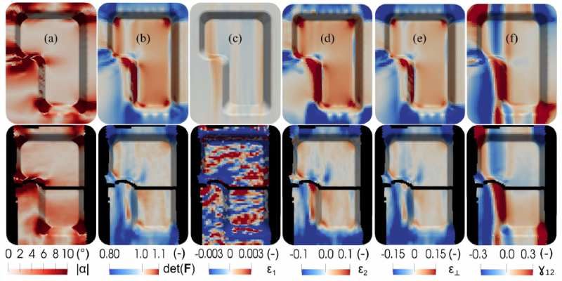
ESAFORM 2021. MS02 (Composite), 10.25518/esaform21.355

Fig. 3. (a) Sil
 Silvver dot grid on semi-finished NCF
 NCF.. (b) Det
 Detect
 ected
 ed dot grid on a def
 deformed
 ormed UD-NCF with associat
 associated
 ed rref
 efer
 erence
 ence
 mar
 markkers [4]. (c) Def
 Deformed
 ormed UD-NCF la
 layyer
 er,, deduced fr
 from
 om the rradiogr
 adiographic
 aphic measur
 measurements
 ements

3.2 Comparison of eexperimental
 xperimental and simulation rresults
 esults
For experimental analysis, the dot grid is applied on the fourth layer (Fig. 3a) and three preforms of identical
configuration are evaluated to account for the scattering during forming. A comparison between the three configurations
showed a very good agreement with negligible deviations. After forming, the coordinates of the displaced dots and
the resulting local deformation gradients are determined. Based on the deformation gradient, local fibre orientations,
area changes and strain measures can be evaluated. According to the UD-NCF material model presented in Section 2.1,
relevant strain measures are the strain components 1 of the fibres and 2 of the stitching, the perpendicular transverse
strain ⊥ and the shear angle 12 between the fibre direction and the second material axis. These can be evaluated and
compared to simulation results.

For forming simulation, the FE model is built up with superimposed membrane and shell elements as described in
Section 2.2. The geometry and the blank holder configurations are defined according to the experimental test setup. To
compare experimental and numerical results, they are transferred to a neutral VTK format and to a uniform mesh. The
mapping library MpCCI.MapLib from Fraunhofer SCAI [19] is used to map both, the data from the experiments and the
data from the simulations, to the uniform mesh.

The comparison between experimental and simulation results is illustrated in Fig. 4 and shows good agreement
regarding fibre orientation and local area change det( ), with an average deviation of only ±2° in fibre orientation
and ±3% in fibre volume content. Since the thickness of the stack is defined by a constant cavity height, the area
change is directly related to the fibre volume content. The largest deviations occur in areas, where the preform recedes
after removal from the mould. Similarly, a good agreement of the shear deformation 12 could be observed, with only
about 2° mean shear angle deviation.

 355/7
Prediction of forming effects in UD-NCF by macroscopic forming simulation – Capabilitie...

 Fig. 4. Comparison betw
 between
 een dr
 draping
 aping simulation (t
 (top)
 op) and eexperiment
 xperiment (bott
 (bottom,
 om, black ar
 areas
 eas without measur
 measurement
 ement
 result): (a) de
 deviation
 viation fr
 from
 om initial fibr
 fibree orientation, (b) local ar
 area
 ea rratio,
 atio, (c) rro
 oving elong
 elongation,
 ation, (d) sewing thr
 thread
 ead
 elong
 elongation,
 ation, (e) tr
 trans
 ansvverse elong
 elongation
 ation tto
 o fibr
 fibree dir
 direction,
 ection, and (f) shear

The largest deviations occur in the elongation 1 in fibre direction and ⊥ in perpendicular direction, as well as in the
elongation 2 of the stitching. Due to the assumption of very stiff fibres, the predicted fibre strain in the simulation is
very small, whereas the experimental tests show diffuse and wave-like strains, which oscillate between compression
and elongation, though at low strain level. In the centre of the geometry a high degree of compression is noticeable
and, in this region, a locally clearly visible waviness was found, which indicates the assumption of negative strains in
fibre direction as an indicator for the onset of waviness. Similar irregular distributed 1 strains have been observed in
OAT tests in case of mesoscopic carbon fibre tow buckling due to lateral contraction of the stitching [11]. The largest
deviations in the elongation 2 of the stitching arise in the area of the inner long side of the L-shaped geometry and
in the bottom area, where different running lengths are realized. One possible reason is that the approach presented
in Section 2 does not restrict slip between carbon fibre, stitching and glass fibre, and thus, neglects potential load
transmission via the glass fibre. This leads to satisfactory results in case of moderate deformations and low blank holder
forces [15], but may lead to noticeable deviations, if slip is restricted. For a more accurate prediction of 1 the material
behaviour in fibre direction needs to be modelled more accurately and advanced modelling approaches are required to
capture in-plane fibre bending. Currently, the compressive stiffness in fibre direction is set equal to the constant tensile
stiffness and buckling is neglected. Negative 1 would then indicate an occurrence of waviness, which in turn leading
to non-linear behaviour of the modulus in fibre direction and to in-plane bending of the roving. In-plane bending
cannot be captured by approaches based on Cauchy mechanics and requires generalized continuum approaches [20].
Introducing an in-plane fibre bending stiffness, would also enable shear stiffness parallel to the fibre tows (21-shear) to
be modelled differently from the macroscopic shear stiffness perpendicular to the fibre tows (12-shear). Experimental
tests show that shear deformation primary occurs parallel to the carbon fibres, since in-plane bending stiffness of the
carbon fibre tows hinders shear deformation perpendicular to the carbon fibres.

4 Conclusions
A macroscopic modelling approach for unidirectional non-crimp fabrics (UD-NCF) is evaluated for its accuracy

 355/8
ESAFORM 2021. MS02 (Composite), 10.25518/esaform21.355

in predicting global and local forming effects. The prediction accuracy is validated by experimental tests, where
full-field strains are measured by projectional radiography. The modelling approach allows for the prediction of
fibre orientations, shear angles and fibre area changes, which all show good agreement with experimental results.
Based on its strain measures, the model can also provide indication for fibre waviness, gapping, and transverse
compaction. Fibre waviness can be deduced from negative strains in fibre direction, provoking fibre buckling. For
a quantitative evaluation, however, the compressive stiffness in fibre direction needs to be known. Furthermore,
advanced generalized continuum approaches are required to capture in-plane fibre bending and the resulting reduced
stiffness in fibre direction. Consequently, the proposed macroscopic approach can provide only a qualitative, but no
quantitative estimation of forming-induced fibre waviness. Transverse compaction and fibre gapping can be deduced
from the strain measures transverse and perpendicular to the fibres. Both show some deviations from experimental
results particularly in areas, where varying running length in fibre direction need to be formed. To predict gapping and
transverse compaction accurately, the multiscale nature of UD-NCF needs to be captured entirely. This includes slip
modelling between carbon fibre, stitching and glass fibre, which depends on the deformation state and on boundary
conditions. While meso-modelling can capture this behaviour intrinsically, a homogenised formulation for macroscopic
modelling remains challenging.

Ackno
 cknowwledgements
The research documented in this manuscript has been funded by the German Research Foundation (DFG), mainly
within the project “Experimental and virtual analysis of draping effects and their impact on the structural mechanical
behaviour of fibre composite components” (No. 287275762) and subsequently within the DFG-ANR project “Composite
forming simulation for non-crimped fabrics based on generalized continuum approaches” (No. 431354059). The
support by the DFG is gratefully acknowledged. The work is also part of the Young Investigator Group (YIG) Tailored
Composite Materials for Lightweight Vehicles, thankfully funded by the Vector Stiftung. The authors are also grateful to
Fraunhofer SCAI for freely providing MpCCI MapLib.

Bibliogr
Bibliograph
 aphyy

[1] Kunze, E. Galkin, S. Böhm, R. Gude, M. Kärger, L. The impact of draping effects on the stiffness and failure behavior of
unidirectional non-crimp fabric fiber reinforced composites. Materials, 2020, 13, 2959. DOI 10.3390/ma13132959.

[2] Kärger, L. Bernath, A. Fritz, F. Galkin, S. Magagnato, D. Oeckerath, A. Schön, A. Henning, F. Development and
validation of a CAE chain for UD fibre reinforced composite components. Composite Structures, 2015, 132, S. 350-358.
DOI 10.1016/j.compstruct.2015.05.047.

[3] Kärger, L. Galkin, S. Zimmerling, C. Dörr, D. Linden, J. Oeckerath, A. Wolf, K. Forming optimisation embedded in a CAE
chain to assess and enhance the structural performance of composite components. Composite Structures, 2018, 192, S.
143-152. DOI 10.1016/j.compstruct.2018.02.041.

[4] Kunze, E. Schwarz, B. Weber, T. Müller, M. Böhm, R. Gude, M. Forming Analysis of Internal Plies of Multi-Layer
Unidirectional Textile Preforms using Projectional Radiography. Procedia Manufacturing, 2020, 47, S. 17-23. DOI
10.1016/j.promfg.2020.04.110.

[5] Mallach, A. Härtel, F. Heieck, F. Fuhr, JP. Middendorf, P. Gude, M. Experimental comparison of a macroscopic draping
simulation for dry non-crimp fabric preforming on a complex geometry by means of optical measurement. Journal of
Composite Materials, 2017, 51(16), S. 2363-2375. DOI: 10.1177/0021998316670477.

[6] Khan, MA. Mabrouki, T. Vidal-Sallé, E. Boisse, P. Numerical and experimental analyses of woven composite

 355/9
Prediction of forming effects in UD-NCF by macroscopic forming simulation – Capabilitie...

reinforcement forming using a hypoelastic behaviour. Application to the double dome benchmark. Journal of Materials
Processing Technology, 2010, 210(2), S :378-388. DOI 10.1016/j.jmatprotec.2009.09.027.

[7] Machado, M. Fischlschweiger, M. Major, Z. A rate-dependent nonorthogonal constitutive model for describing shear
behaviour of woven reinforced thermoplastic composites. Composites Part A, 2016, 80, S. 194-203. DOI 10.1016/
j.compositesa.2015.10.028.

[8] Lin, H. Long, AC. Sherburn, M. Clifford, MJ. Modelling of mechanical behaviour for woven fabrics under combined
loading. International Journal of Material Forming, 2008, 1(1), S. 899-902. DOI 10.1007/s12289-008-0241-7.

[9] Lomov, SV. Ivanov, D. Verpoest, I. Zako, M. Kurashi, T. Nakai, H. Hirosawa, S. Meso-FE modelling of textile composites:
Road map, data flow and algorithms. Composites Science and Technology, 2007, 67(9), S. 1870–1891. DOI 10.1016/
j.compscitech.2006.10.017.

[10] Sirtautas, J. Pickett, AK. Lépicier, P. A mesoscopic model for coupled drape-infusion simulation of biaxial non-crimp
fabric. Composites Part B, 2013, 47, S. 48-57. DOI 10.1016/j.compositesb.2012.09.088.

[11] Schirmaier, F.J. Dörr, D. Henning, F. Kärger, L. A macroscopic approach to simulate the forming behaviour of stitched
unidirectional non-crimp fabrics. Composites Part A, 2017, 102, S. 322-335. DOI 10.1016/j.compositesa.2017.08.009.

[12] Böhler, P. Härtel, F. Middendorf, P. Identification of Forming Limits for Unidirectional Carbon Textiles in Reality
and Mesoscopic Simulation. Key Engineering Materials 2013, 554-557, S. 423-432. DOI 10.4028/www.scientific.net/
KEM.554-557.423.

[13] Senner, T. Kreissl, S. Merklein, M. Meinhardt, J. Lipp, A. A modular modeling approach for describing the in-plane
forming behavior of unidirectional non-crimp-fabrics. Production Engineering Res. Devel., 2014, 8(5), S. 635–643. DOI:
10.1007/s11740-014-0561-z.

[14] Senner, T. Kreissl, S. Merklein, M. Meinhardt, M. Lipp, A. Bending of unidirectional non-crimp-fabrics: experimental
characterization, constitutive modeling and application in finite element simulation. Production Engineering Res. Devel,
2015, 9, S. 1-10. DOI: 10.1007/s11740-014-0568-5.

[15] Kärger, L. Galkin, S. Dörr, D. Poppe, C. Capabilities of Macroscopic Forming Simulation for Large-Scale
Forming Processes of Dry and Impregnated Textiles. Procedia Manufacturing, 2020, 47, S. 140-147. DOI /10.1016/
j.promfg.2020.04.155.

[16] Schirmaier, F.J. Weidenmann, K.A. Kärger, L. Henning, F. Characterisation of the draping behaviour of unidirectional
non-crimp fabrics (UD-NCF). Composites Part A, 2016, 80, S. 28–38. DOI 10.1016/j.compositesa.2015.10.004.

[17] Galkin, J. Kunze, E. Kärger, L. Böhm, R. Gude, M. Experimental and numerical determination of the local fiber
volume content of unidirectional non-crimp fabrics with forming effects. Journal of Composites Science, 2019, 3, 19.
DOI 10.3390/jcs3010019.

[18] Dörr, D. Schirmaier, F. Henning, F. Kärger, L. A viscoelastic approach for modeling bending behavior in FE forming
simulation of continuously fiber reinforced composites. Composites Part A, 2017, 94, S. 113-123. DOI 10.1016/
j.compositesa.2016.11.027.

[19] Wolf, K. Bayrasy, P. Brodbeck, C. Kalmykov, I. Oeckerath, A. Wirth, N. MpCCI: Neutral Interfaces for Multiphysics
Simulations. In: Griebel M. Schüller A. Schweitzer M (eds): Scientific Computing and Algorithms in Industrial
Simulations. Cham: Springer International Publishing, 2017, S. 135-51. DOI: 10.1007/978-3-319-62458-7_7.

 355/10
ESAFORM 2021. MS02 (Composite), 10.25518/esaform21.355

[20] Barbagallo G. Madeo A. Azehaf I. Giorgio I. Morestin F. Boisse P. Bias extension test on an unbalanced woven
composite reinforcement: Experiments and modeling via a second-gradient continuum approach. Journal of Composite
Materials 51(2):153–170, 2017. DOI 10.1177/0021998316643577.

PDF automatically generated on 2021-05-19 11:52:56
Article url: https://popups.uliege.be/esaform21/index.php?id=355
published by ULiège Library in Open Access under the terms and conditions of the CC-BY License
(https://creativecommons.org/licenses/by/4.0)

 355/11
You can also read