Preliminary Navigation Study
←
→
Page content transcription
If your browser does not render page correctly, please read the page content below
Preliminary Navigation
Study
Multnomah County | Earthquake Ready
Burnside Bridge Project
Portland, OR

January 29, 2021
Earthquake Ready Burnside Bridge
Preliminary Navigation Study

Prepared for

Multnomah County
Transportation Division – Bridges
1403 SE Water Ave
Portland, OR 97214

Prepared by

HDR
1050 SW 6th Avenue, Suite 1800
Portland, OR 97204
T (503) 423-3700

Glosten
1201 Western Avenue, Suite 200
Seattle, WA 98101-2921
T (206) 624-7850

Contract# DCS-SVCSGEN-857-2019-conv
HDR Project #10144814
CERTIFICATION
The technical material and data contained in this document were prepared under the supervision
and direction of the undersigned, as a professional engineer.

                                Signature Reserved for Final Version
 Prepared by Zenzile Moore (Naval Architect)

                                Signature Reserved for Final Version
 Checked by Matthew Lankowski (Subconsultant Project Manager, PE)

                                Signature Reserved for Final Version
 Approved by Heather Catron (Consultant Project Manager)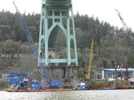
Preliminary Navigation Study
Multnomah County | Earthquake Ready Burnside Bridge Project
Contents
Executive Summary ....................................................................................................................1
1 Introduction .......................................................................................................................1
1.1 Overview of Navigation Requirements...........................................................................1
1.2 Purpose ...................................................................................................................3
1.3 Methods and Data Sources .........................................................................................3
1.3.1 Literature Review............................................................................................3
1.3.2 Site Visit........................................................................................................4
1.3.3 River User Master List .....................................................................................5
1.4 Maximum River User Clearance Requirements...............................................................5
1.5 Bridge Design States ..................................................................................................6
2 Existing Navigation Use and Requirements ............................................................................7
2.1 Existing Bridge and Cable Crossing Clearances .............................................................7
2.1.1 Governing Navigation Limitations ......................................................................8
2.2 Navigation Channel.................................................................................................. 10
2.2.1 Waterway Layout and Geometry ..................................................................... 10
2.2.2 Hydrology and Waterway Natural Flow............................................................. 12
2.2.3 Waterway Depth and Elevation Fluctuations ..................................................... 13
2.2.4 Maintenance Dredging .................................................................................. 15
2.2.5 Guide Clearances ......................................................................................... 16
2.2.6 Channel and Waterway Alignment................................................................... 16
3 Future Development and Adopted Plans .............................................................................. 17
3.1 Portland Urban Plan History ...................................................................................... 17
3.2 Willamette Greenway Plan Goal and Objectives ........................................................... 17
3.3 Central City Plan...................................................................................................... 18
3.4 Oregon’s Statewide Planning Goals & Guidelines ......................................................... 18
3.5 River Renaissance................................................................................................... 19
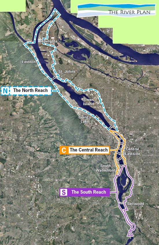
3.6 River Plan............................................................................................................... 19
3.7 Development Impacts on River .................................................................................. 21
4 Burnside Bridge Clearances............................................................................................... 22
4.1 Overview ................................................................................................................ 22
4.2 Commercial Users ................................................................................................... 23
4.2.1 Waterborne Commerce Statistics .................................................................... 33
4.3 Recreational Users................................................................................................... 34
4.4 Government Users ................................................................................................... 36
4.5 Bridge Clearance Recommendations .......................................................................... 38
4.5.1 Recommended Vertical Clearance Elevation..................................................... 38
4.5.2 Recommended Horizontal Clearance............................................................... 39
4.5.3 Clearance Window........................................................................................ 42
4.5.4 Navigation Impacts and Recommendations ...................................................... 42
5 Earthquake Response Vessels ........................................................................................... 44
5.1 Overview ................................................................................................................ 44
5.2 Summary of Findings................................................................................................ 44
January 29, 2021 | i
Preliminary Navigation Study
                                                                    Multnomah County | Earthquake Ready Burnside Bridge Project

               5.2.1     Initial Response............................................................................................ 44
               5.2.2     Considerations of Deep Draft Vessels .............................................................. 47
6      Conclusions and Recommendations.................................................................................... 48
       6.1     Minimum Recommended Elevation............................................................................. 48
       6.2     Minimum Recommended Horizontal Clearance ............................................................ 48
       6.3     Bridge Width ........................................................................................................... 48
       6.4     Impact of Clearance Requirements on Bridge Design States .......................................... 49
7      Ref erences...................................................................................................................... 50

                                                              Tables
Table 1. Most Restrictive Clearances of Bridge Design States ...........................................................2
Table 2. Horizontal Clearance Requirements of Impacted Tug and Barge River Users...........................5
Table 3. Maximum River User Elevations and Horizontal Clearance Requirements ...............................5
Table 4. Required Burnside Bridge Clearances at Various Design States ............................................6
Table 5. Willamette River Bridges and Crossings, Mouth to Mile 25.9 .................................................7
Table 6. Most Restrictive Horizontal Clearances on Willamette River ..................................................9
Table 7. Most Restrictive Elevations on Willamette River ..................................................................9
Table 8. Most Restrictive Clearances on Willamette River ............................................................... 10
Table 9. Willamette River Discharge ............................................................................................ 13
Table 10. Willamette River Tidal Stations...................................................................................... 14
Table 11. Willamette River Guide Clearances................................................................................ 16
Table 12. Navigation Channels on Willamette River ....................................................................... 17
Table 13. River Plan Reaches and Themes .................................................................................. 20
Table 14. River Plans Projects Potentially Impacting River Traff ic, Flow, or Footprint........................... 21
Table 15. Horizontal Clearance Requirements of Impacted Tug and Barge River Users ....................... 26
Table 16. Assumed Horizontal Clearance if a Single Leaf Must Be Closed......................................... 41

                                                             Figures
Figure 1. Horizontal Clearance between Bridge Piers and Upriver/Downriver Bridge Width ....................2
Figure 2. Distribution of River Users...............................................................................................3
Figure 3. Elevation and Corresponding Horizontal Clearance for Each River User Type.........................4
Figure 4. Glosten Staff on River Survey Near Ross Island and St. John’s Bridge ..................................4
Figure 5. Horizontal Clearance between Bridge Piers and Upriver/Downriver Bridge Width ....................6
Figure 6. Willamette River Basin (green), Willamette River (black), and Oregon Counties .................... 11
Figure 7. Willamette River Waterway Layout in Vicinity of Burnside Bridge......................................... 12
Figure 8. Expected Tidal and Flood Elevations at Morrison Bridge (WRM 12.8) .................................. 14
Figure 9. River Plan Reaches ..................................................................................................... 20
Figure 10. Distribution of River Users ........................................................................................... 22
Figure 11. Tug and Barge Users - Required Vertical Clearance Elevations (top) and Required
        Horizontal Clearance Widths (bottom)............................................................................... 24
Figure 12. Foss (left) and AAC (right) Facilities on the Willamette River............................................. 26

ii | January 29, 2021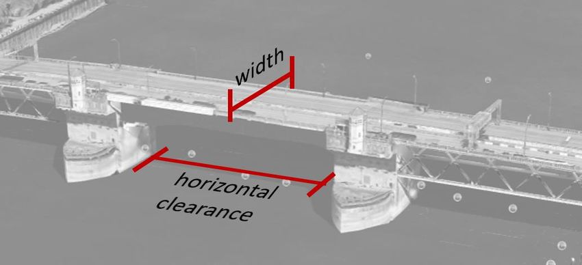
Preliminary Navigation Study
Multnomah County | Earthquake Ready Burnside Bridge Project
Figure 13. Cruise Ship Users - Required Vertical Clearance Elevations (top) and Required
Horizontal Clearance Widths (bottom)............................................................................... 27
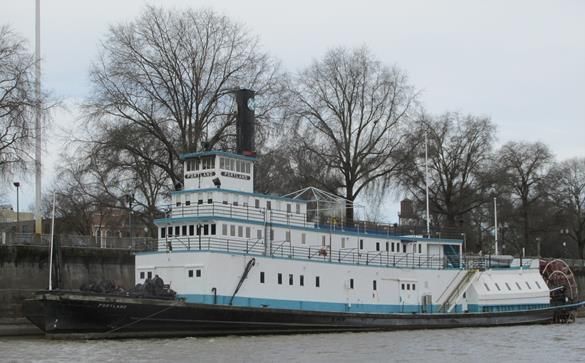
Figure 14. The Oregon Maritime Museum Sternwheeler Portland ..................................................... 29
Figure 15. Visitors and Fleet Week Vessels - Required Vertical Clearance Elevations (left) and
Required Horizontal Clearance Widths (right)..................................................................... 30
Figure 16. MS The World ........................................................................................................... 31
Figure 17. Diagram of Fleet Week Vessel Mooring Plan.................................................................. 32
Figure 18. Fleet Week Vessels with Air Drafts Greater Than 100 Feet That Transited Through the
Burnside Bridge, 2008 – 2018.......................................................................................... 32
Figure 19. Upper Willamette and Yamhill River commerce between 2007 and 2016 ............................ 33
Figure 20. Recreational users - Required Vertical Clearance Elevations (top) and Required
Horizontal Clearance Widths (bottom)............................................................................... 35
Figure 21. Government Users - Required Vertical Clearance Elevations (top) and Required
Horizontal Clearance Widths (bottom)............................................................................... 37
Figure 22. Elevation Requirements of All Known River Users........................................................... 39
Figure 23. Horizontal Clearance Requirements of All Known River Users .......................................... 40
Figure 24. Elevation Requirement and Corresponding Horizontal Clearance Requirement for
Each River User Type .................................................................................................... 42
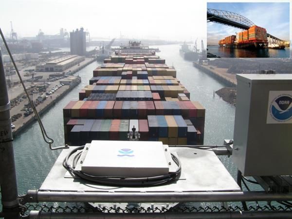
Figure 25. Air Gap Sensor on Gerald Desmond Bridge in Long Beach, California ............................... 43
Figure 26. Representative Derrick Barge ...................................................................................... 47
Appendices
Appendix A. River User Master List ........................................................................................... A-1
Appendix B. River Users Removed from Analysis ........................................................................ B-1
Appendix C. Select River User Navigation Feedback.................................................................... C-1
January 29, 2021 | iii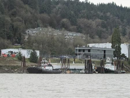
Preliminary Navigation Study
                                              Multnomah County | Earthquake Ready Burnside Bridge Project

                        Acronyms, Initialisms, and Abbreviations

              AAC                   Advanced American Construction
              AEP                   Annual Exceedance Probability
              BPS                   City of Portland Bureau of Planning and Sustainability
              CFR                   Code of Federal Regulations
              CRD                   Columbia River Datum
              EPA                   U.S. Environmental Protection Agency
              EQRB                  Earthquake Ready Burnside Bridge
              FEMA                  Federal Emergency Management Agency
              FHWA                  Federal Highway Administration
              FR                    Federal Register
              LCDC                  Oregon Land Conservation and Development
                                    Commission
              MHHW                  Mean higher high water
              MHW                   Mean high water
              MLLW                  Mean lower low water
              MLW                   Mean low water
              MTSRU                 USCG Marine Transportation System Recovery Unit
              NAVD 88               North American Vertical Datum 1988
              NEPA                  National Environmental Policy Act of 1969
              NGVD 29               National Geodetic Vertical Datum of 1929
              NOAA                  National Oceanic and Atmospheric Administration
              ODOT                  Oregon Department of Transportation
              OHW                   Ordinary high water
              PNERC                 Pacif ic Northwest Ecosystem Research Consortium
              SAR                   Search and rescue
              USACE                 U.S. Army Corps of Engineers
              USC                   United States Code
              USCG                  U.S. Coast Guard
              USGS                  U.S. Geological Survey
              WRM                   Willamette River Mile

iv | January 29, 2021
Preliminary Navigation Study
Multnomah County | Earthquake Ready Burnside Bridge Project
Executive Summary
The Burnside Bridge in Portland is being made “earthquake-ready” as part of the
Earthquake Ready Burnside Bridge project. The purpose of this report is to summarize
the impacts to navigation of the Burnside Bridge replacement projects during temporary
and permanent bridge phases. This report provides substantial input towards the
complete Navigation Impact Report prepared b y HDR as part of a U.S. Coast Guard
(USCG) Bridge Permit Application.
Recommended Clearances
The USCG requirement to enable 100 percent of vessel traf fic to safely transit under the
bridge drives the clearance recommendations within this study. The recommendations
herein ref lect the minimum clearances that will allow all vessel traf f ic to safely transit the
bridge.
The recommended minimum clearance elevation for all bridge design states is
167 feet above the NAVD 88 datum. The recommended horizontal clearance for all
bridge design states is 205 feet.
The recommended vertical clearance is based on the maximum air draf t of all known
river users above ordinary high water (OHW), the water level accepted as a design
elevation by the USCG and USACE.
For short-term reductions to these clearances during construction, it is reasonable to
assume that the USCG will grant temporary deviations to these clearance dimensions,
as evidenced by the many recent rehabilitation projects. These temporary deviations,
however, are on a case-by-case basis only and should be limited to days and a f ew
weeks rather than months. Temporary deviations may require agreements f rom af fected
river users.
Bridge Design States
The objective of this study was to determine minimum clearance requirements
independent of bridges or any other man-made obstructions. However, many river users
could not articulate their clearance requirements without a starting point to consider. This
starting point was provided as a set of Bridge Design States, representing minimum
existing and proposed clearances. A variety of bridge designs are being considered f or
this project. All bridge designs f all into one of four states:
• Existing. The current Burnside Bridge. This bascule bridge has dif ferent vertical
clearances in the lowered and raised positions.
• Temporary. A temporary construction phase consisting of a vertical lif t bridge with
limited clearances. This phase will ultimately lead to a dif f erent bridge design state.
• Permanent Retrofit. Earthquake retrof it of the current bascule Burnside Bridge, with
no impact on existing clearances in the lowered and raised positions .
• Permanent Replacement. The permanent design f or a replacement Burnside Bridge,
with permanent changes to existing clearances.
January 29, 2021 | ES-1Preliminary Navigation Study
Multnomah County | Earthquake Ready Burnside Bridge Project
Table 1 presents the most restrictive elevation and horizontal clearance of the bridge
designs being considered for each design state as communicated by the HDR Bridge
Design Team1.
Table 1. Most Restrictive Clearances of Bridge Design States
Horizontal Bridge Width
Design State Elevation
Clearance (ft. upriver / downriver)
Existing 69 ft. above NAVD 88 205 ft. 86 ft.
(closed); Infinite (raised)
Temporary 167 ft. above NAVD 88 165 ft. 220 ft. to 390 ft.
(raised)
Permanent Retrofit 69 ft. above NAVD 88 205 ft. 86 ft.
(closed); Infinite (raised)
Permanent 69 ft. above NAVD 88 205 ft. 150 ft. to 195 ft.
Replacement (closed); Infinite (raised)
Elevation ref ers to distance above North American Vertical Datum 1988 (NAVD 88) or
the Columbia River Datum (CRD), as noted. Horizontal clearance ref ers to the clear
distance between bridge piers. This study assumes the center of the navigation channel
will remain the same as the existing Burnside Bridge. Bridge width ref ers to the
upriver/downriver distance f or transiting under the bridge (Figure 1).
Figure 1. Horizontal Clearance between Bridge Piers and Upriver/Downriver Bridge Width
Source: Google Earth
River Users
In this study, a river user is a public or private entity expected to transit the Burnside
Bridge in a vessel during and/or af ter Burnside Bridge modification. A river user may be
an individual (such as a private vessel owner) or a group (such as a company, marina, or
organization).
1
Bautista, R. (email) [HDR], “RE: EQRB NEPA: Navigation Study Report Rev P1 Rev 2 Package
Comments,” 14 June 2019
ES-2 | January 29, 2021Preliminary Navigation Study
Multnomah County | Earthquake Ready Burnside Bridge Project
As part of this study, 84 river users potentially af fected by a change in clearance of the
Burnside Bridge were contacted or researched . Elevations and horizontal clearance
requirements were ultimately obtained f or 47 river users. These 47 users are a
representative subset of the thousands of actual river users who may transit under the
Burnside Bridge. They f all into three main types: commercial, recreational, or
government, as shown in Figure 2.
Figure 2. Distribution of River Users
Elevation and horizontal clearance requirements are provided by the river users
themselves. These requirements represent their stated minimum space needed to saf ely
transit the bridge. The basis f or these requirements, such as the season and water
surf ace elevation, varies f rom river user to river user.
Elevation and horizontal clearance requirements combine to f orm a clearance window.
Figure 3 displays the clearance windows f or the vessels with the largest clearances in
each user type.
January 29, 2021 | ES-3Preliminary Navigation Study
Multnomah County | Earthquake Ready Burnside Bridge Project
Figure 3. Elevation and Corresponding Horizontal Clearance for Each River User Type
The height and width of each box in Figure 3 correspond to the required elevation and
horizontal clearance (centered on the navigation channel) f or each vessel.
Impact of Recommended Clearances on Bridge Design States
All bridge design states currently satisf y the recommended elevation of 167 f eet above
NAVD 88.
Three bridge design states satisfy the recommended horizontal clearance of 205 f eet:
existing, permanent retrof it, and permanent replacement.
The 165-f oot horizontal clearance of the temporary bridge design state would impose an
operations impact on three known river users, which would be mitigated via tug -assist, as
stated below:
• Combined Forestry reported that they could not transit saf ely, but one or two tug
assists could mitigate the impact. However, tug assists would not guarantee saf e
transit f or Combined Forestry.
• Advanced American Construction (AAC) reported that they would require a tug assist
f or saf e transit.
• Shaver Transportation reported that they would require a tug assist on a case-by-
case basis.
ES-4 | January 29, 2021Preliminary Navigation Study
Multnomah County | Earthquake Ready Burnside Bridge Project
• Table 2 summarizes the horizontal clearance requirements of these impacted tug
and barge river users.
Table 2. Horizontal Clearance Requirements of Impacted Tug and Barge
River Users
Horizontal
Temporary Bridge
User Clearance
(considering a 165 ft. to 390 ft. width range)
Requirement
Combined Forestry & 205 ft. No safe transit, but tug assist may mitigate the impact
Marine Services, Inc.
Shaver Transportation 200 ft. Safe transit with 1 tug assist (on case-by-case basis)
AAC 185 ft. Safe transit with 1 tug assist
Moreover, the Columbia River Pilots advised against narrowing the Burnside Bridge. The
Burnside Bridge is the narrowest bridge in the Sellwood Reach (the Willamette River
downstream of the Sellwood Bridge). The temporary bridge would become the most
restrictive horizontal clearance on the waterway. Any reduction to its horizontal clearance
at either the temporary or permanent phases will require negotiation with these impacted
river users.
Bridge upriver/downriver width (Figure 1) also has navigation impacts. If a replacement
bridge requires a temporary bridge during construction, then transit width could range
f rom 220 f eet to 390 f eet, subject to how the contractor might construct the bridge. Some
river users would require a tug assist due to this extensive bridge width. The transit width
of the permanent bridge would range f rom 150 f eet to 195 f eet, subject to the exact
length of the pier f ender system to be implemented . River users do not anticipate
requiring regular tug assists to navigate this bridge width. Depending on f uture project
work and river conditions, occasional tug assist may be needed . One river user
recommended widening the horizontal clearance to aid navigation through the longer
bridge corridor.
Based on f eedback f rom participating river users and vertical and horizontal clearance
requirements, several recommendations are presented f or the design and construction of
the Earthquake Ready Burnside Bridge project:
• Clear navigation signage f or both commercial and recreational vessel operators.
• Dedicated transit lane f or small recreational craf t such as kayaks and stand-up
paddleboards.
• Real-time vertical clearance gauge to inf orm vessel operators whether they clear the
bridge at any given moment or river level.
January 29, 2021 | ES-5Preliminary Navigation Study
Multnomah County | Earthquake Ready Burnside Bridge Project
This page is intentionally left blank.
ES-6 | January 29, 2021Preliminary Navigation Study
Multnomah County | Earthquake Ready Burnside Bridge Project
1 Introduction
1.1 Overview of Navigation Requirements
According to 33 CFR Part 329, navigable waters of the United States are those waters
that are subject to the ebb and f low of the tide and/or are presently used, or have been
used in the past, or may be susceptible f or use to transport interstate or f oreign
commerce. A determination of navigability, once made, applies laterally over the entire
surf ace of the waterbody, and is not extinguished by later actions or events which
impede or destroy navigable capacity (33 CFR §329.4, Def inition of Navigable Waters of
the US, 2019).
In ef f ect, once a waterway has been deemed navigable, its navigability may not be
diminished. This report analyzes the historical and possible future use of the Willamette
River at the Burnside Bridge to determine the minimum clearances required to ensure
navigability is not diminished, based on existing and anticipated f uture traf fic in the
Sellwood Reach (the Willamette River downstream of the Sellwood Bridge).
Code of Federal Regulations
33 CFR Subchapter J sets the requirements f or the locations and clearances of bridges
and causeways over navigable waters (33 CFR §33.114-116, Navigation and Navigable
Waters, 2019). Part 114 establishes the District Commander (USCG) as the reviewer of
bridge permit applications, and details permitting procedures. Special protocols are
provided in Part 115 if a bridge is determined to be an unreasonable obstruction to
navigation. Drawbridges and bridge lighting are also reviewed in Part 116.
33 CFR Subchapter P governs Ports and Waterway Saf ety (33 CFR §33.162-163,
Navigation and Navigable Waters, 2019). Specif ic detail concerning the Willamette River
is provided in Part 162. The District Commander of the Thirteenth Coast Guard District is
given administrative supervision and the responsibility to enforce emergency regulations
concerning navigation, such as speed regulations during f looding or construction. Part
163 limits the length of seagoing barge tows in inland waters.
U.S. Coast Guard Bridge Permit Application
The USCG provides written approval of the location and plans f or proposed bridges or
causeways over navigable waterways (USCG 2016). The Bridge Permit Application is
the medium f or the USCG written approval. The three primary components of the Bridge
Permit Application are:
1. Proposed bridge description.
2. Environmental documentation.
3. Plan sheets.
In addition to the above, applicants must provide a Navigation Impact Report. This
report summarizes current and prospective navigation on a waterway and analyzes the
January 29, 2021 | 1Preliminary Navigation Study
Multnomah County | Earthquake Ready Burnside Bridge Project
navigational impacts of the proposed bridge designs. Data f or this report is collected by
both Bridge Permit applicants and the USCG, and may include:
• Visits, including site visits, ride-alongs, and public meetings.
• Written Communications, such as public notices f or comment, advertisements, and
surveys.
• Research, including review of bridge tender logs, USACE Engineer Manuals design
guidance, and waterborne commerce statistics.
The Navigation Impact Report draws on this data to describe key navigation aspects:
• Nearby structures, including bridges, federal navigation projects, marine f acilities,
and harbors of ref uge.
• Waterway characteristics, including bends in the waterway, hydraulic conditions,
atmospheric conditions, and guide clearances.
• Waterway users, including service f acilities, and vessels f or emergency response,
def ense, maintenance, commerce, and recreation.
• Alternate waterway routes.
Proposed developments that will af fect navigation aspects are also discussed.
U.S. Coast Guard Direct Guidance
In developing this Navigation Study, USCG has advised key study elements through
meetings and email communication. Based on this guidance, the navigable waterway is
assumed to run f rom bank to bank on the Willamette River. No f ederally maintained
channel exists near the Burnside Bridge to restrict the width of the navigable waterway
(Section 2.2.6).
USCG stated that 100 percent of vessel traf f ic must be able to saf ely transit the
permanent and temporary bridge, unless a compelling reason exists otherwise. An
example compelling reason would be a written agreement between the City of Portland,
Multnomah County, and the river user unable to pass . The agreement would state all
parties agree that the restricted river user will not be able to transit the Burnside Bridge
f or the f oreseeable lif e of the permanent or temporary bridge. As part of the user survey,
restricted use was discussed with the river users and some users may be unwilling to
reduce their transit rights if it af f ects their projects at that time. Formal restricted use
agreements were not pursued as part of this study.
Ultimately, the USCG requirement to enable 100 percent of vessel traf fic to safely transit
the permanent and temporary bridge led to the vertical and horizontal clearance
requirements in this report. These clearance requirements ref lect the minimum
clearances that will allow all known river users to saf ely transit the bridge. The USCG
stresses that a bridge replacement or modif ication project of this duration and with this
many stakeholders will have evolving stakeholder needs over time. Establishing
navigability requirements is necessarily an iterative process . Navigability requirements
must be periodically revisited throughout the project to ensure no previously unknown
river users have become known, or known river user needs have changed.
2 | January 29, 2021Preliminary Navigation Study
Multnomah County | Earthquake Ready Burnside Bridge Project
Single-Leaf Closures
Temporary single-leaf closures are a possibility during the construction of any b ascule
bridge. USCG grants permission f or a temporary single-leaf closure via two mechanisms:
• Temporary Deviation, f or closures under 180 days in duration (minimum 90-day
application period).
• Temporary Rule, f or closures exceeding 180 days in duration with no maximum
duration (minimum three or f our month application period).
These mechanisms are f ully detailed in 33 CFR §117.35. They represent deviation f rom
the normal operating rules of the Burnside Bridge, detailed in 33 CFR §117.897(c)(3)(iii).
Temporary Rules and Temporary Deviations are totally separate f rom the USCG Bridge
Permit Application described above.
Both Temporary Deviations and Temporary Rules require 100 percent consent f rom
vessel traf f ic. For example, if a particular river user cannot saf ely transit the bridge during
the single-leaf closure, the Temporary Deviation or Temporary Rule application must
include permission f rom that af fected user to f orego transit during the closure period .
USCG will independently check potentially af fected users to confirm the applicant has
suf f iciently canvassed river users. River users who are anticipated to be af f ected by
single leaf closures of the Burnside Bridge are detailed in Sectio n 4.5.2.
USCG approval does not depend on time of year or the number of consecutive
Rules/Deviations. USCG approval does depend on consent from affected users . To this
end, the Temporary Rule / Temporary Deviation applicant is encouraged to consider
mitigation with af f ected users. For example, if the applicant provides alternate moorage
f or af f ected users, these users may be more likely to consent to f orego transit during the
closure period.
1.2 Purpose
This report summarizes the impacts to navigation of the Burnside Bridge replacement
projects during temporary and permanent bridge phases . This report provides substantial
input towards the complete Navigation Impact Report prepared by HDR as part of a
USCG Bridge Permit Application.
1.3 Methods and Data Sources
1.3.1 Literature Review
Glosten reviewed background materials in three areas: regulations, river hy drology, and
urban development. Key materials in each area include:
• Regulations
o USCG Bridge Permit Application Guide.
o USCG Guide Clearances.
o Code of Federal Regulations.
o Oregon Department of State Lands.
January 29, 2021 | 3Preliminary Navigation Study
Multnomah County | Earthquake Ready Burnside Bridge Project
o Oregon Department of Land Conservation and Development.
• River Hydrology
o USGS tidal and f lood elevations.
o National Geodetic Survey vertical datums.
o National Oceanic and Atmospheric Administration Charts.
o Department of the Army Corps of Engineers Waterborne Commerce Statistics.
• Urban Development
o City of Portland River Renaissance.
o City of Portland River Plan.
o Oregon Department of Land Conservation and Development Oregon’s Statewide
Planning Goals & Guidelines.
o Portland-Milwaukie Light Rail Project Final Environmental Impact Statement,
Navigation Study.
Glosten also summarized existing bridge clearances upstream and downstream of
Burnside Bridge. The literature provided a f oundational understanding of the Willamette
River. Multnomah County bridge opening data was researched but the data obtained did
not prove to be valuable.
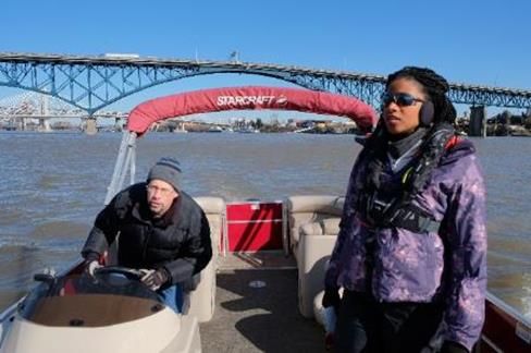
1.3.2 Site Visit
On 26 March 2019, Glosten conducted a site visit to physically assess the Burnside
Bridge, traf f ic patterns, and local vessels. The site visit was comprised of a 20-mile
pontoon boat cruise f rom the St. John’s Bridge (Willamette River Mile (WRM) 5.8) to the
Willamette Falls (approximately WRM 26). On the cruise, Glosten staf f visually inspected
the Burnside Bridge, other bridges, local sites and businesses, and vessel traffic . Staff
also visited businesses and marinas on Multnomah Channel and the Columbia River
near the mouth of the Willamette. The visit provided a current snapshot of operations on
the Willamette River. Glosten staf f also performed land-based visual inspections of the
Burnside Bridge, other nearby bridges, and sites and businesses in the area.
Figure 4. Glosten Staff on River Survey Near Ross Island and St. John’s Bridge
4 | January 29, 2021Preliminary Navigation Study
Multnomah County | Earthquake Ready Burnside Bridge Project
1.3.3 River User Master List
The Literature Review and Site Visit inf ormed development of the River User Master List .
The List contains 84 river users potentially af fected by changing Burnside Bridge
clearances. Users without signif icant marine assets in the project area or who declined
response were typically omitted from further study (Appendix B).
Required inf ormation was f ound via other methods f or some unresponsive users . Those
users were included in the evaluation of elevation and horizontal clearance requirements
despite being unresponsive.
The List provides the f ollowing information (as available) f or each river user:
• Brief description.
• Contact inf ormation (phone and email).
• Contact history f or this Navigation Study.
• Elevation requirement at the Burnside Bridge.
• Horizontal clearance requirement at the Burnside Bridge.
1.4 Maximum River User Clearance Requirements
Elevations and horizontal clearance requirements were ultimately obtained f or 47 users
(Appendix A). Table 3 presents the maximum requirements f rom that group .
Table 3. Maximum River User Elevations and Horizontal Clearance
Requirements
User Clearance Controlling River User
Maximum River User Vertical 147 ft air draft (Elevation Fleet Week (USCG Waesche)
Clearance Elevation 167 ft. above NAVD 88 at
Burnside Bridge)
142 ft air draft (Elevation M/V The World
162 ft. above NAVD88 at
Burnside Bridge)
Maximum River User Horizontal 205 ft. Combined Forestry and Marine
Clearance Requirement Services, Inc.
The maximum river user elevation equals the minimum bridge elevation requirement.
The maximum river user horizontal clearance requirement equals the minimum bridge
horizontal clearance requirement. The requirements in Table 3 ref lect river user needs at
the time of this study. River users and their requirements may change over time as the
project develops. Thus, the maximum requirements are subject to change during the
course of the project.
Bridge upriver/downriver width (Figure 1) also has navigation impacts. The transit width
of the alternative with a temporary bridge could range f rom 220 f eet to 390 f eet, subject
to how the contractor might construct the bridge. Some river users would require a tug
assist due to this extensive bridge width. The transit width of t he permanent bridge would
January 29, 2021 | 5Preliminary Navigation Study
Multnomah County | Earthquake Ready Burnside Bridge Project
range f rom 150 f eet to 195 f eet, subject to the exact length of the pier f ender system to
be implemented. River users do not anticipate requiring regular tug assists to navigate
this bridge width. Depending on f uture project work and river conditions, occasional tug
assist may be needed. One river user recommended widening the horizontal clearance
to aid navigation through the longer bridge corridor.
1.5 Bridge Design States
The objective of this study was to determine minimum clearanc e requirements
independent of bridges or any other man-made obstructions. However, many river users
could not articulate their clearance requirements without a starting point to consider. This
starting point was provided as a set of Bridge Design States, representing minimum
existing and proposed clearances.
The bridge designs f or the Earthquake Ready Burnside Bridge project f all into one of four
states. Table 4 presents those states and their dimensions, which represent the most
restrictive elevation and horizontal clearance of all bridge designs within each state.
Table 4. Required Burnside Bridge Clearances at Various Design States
Vertical Clearance Horizontal Bridge Width
Design State
(Elevation) Clearance (ft. upriver/downriver)
Existing 69 ft. above NAVD 88 205 ft. 86 ft.
(closed); Infinite (raised)
Temporary 167 ft. above NAVD 88 165 ft. 220 ft. to 390 ft.
(raised)
Permanent Retrofit 69 ft. above NAVD 88 205 ft. 86 ft.
(closed); Infinite (raised)
Permanent 69 ft. above NAVD 88 205 ft. 150 ft. to 195 ft.
Replacement (closed); Infinite (raised)
Elevation ref ers to vertical clearance above North American Vertical Datum 1988
(NAVD 88) or the Columbia River Datum (CRD), as noted. Horizontal clearance ref ers to
the clear distance between bridge piers. Width ref ers to the upriver/downriver distance
f or transiting under the bridge (Figure 5).
Figure 5. Horizontal Clearance between Bridge Piers and Upriver/Downriver Bridge Width
6 | January 29, 2021Preliminary Navigation Study
Multnomah County | Earthquake Ready Burnside Bridg e Project
Note: The width shown does not include any temporary bridge works anticipated during construction.
Source: Google Earth
The elevations of all bridge states meet or exceed the maximum elevation of all river
users.
The 165-f oot horizontal clearance of the temporary bridge state would impose an
operations impact on three known river users, which would be mitigated via tug-assist, as
stated below:
• Combined Forestry reported that they could not transit saf ely, but one or two tug
assists could mitigate the impact. However, tug assists would not guarantee saf e
transit f or Combined Forestry.
• AAC reported that they would require a tug assist f or safe transit.
• Shaver Transportation reported that they would require a tug assist on a case-by-
case basis.
2 Existing Navigation Use and Requirements
2.1 Existing Bridge and Cable Crossing Clearances
Fif teen bridges and f our cables cross the Willamette River between mouth and the
Willamette Falls (Table 5). Elevations when comparing bridges are given with respect to
the Columbia River Datum (CRD), which varies along the length of the Willamette River.
Table 5. Willamette River Bridges and Crossings, Mouth to Mile 25.9
Elevation Elevation
Horizontal Horizontal
Bridge/Interference Milepost ft. above (Raised) ft.
(Closed) ft. (Raised) ft.
CRD* above CRD
St. Johns Bridge 6.0 205 1068 - -
St. Johns Railroad Bridge 7.0 54 499 200 499
(Burlington Northern RR
Bridge 5.1)
Fremont Bridge 11.1 163 928 - -
Broadway Bridge 11.7 90 251 Infinite 251**
Steel Bridge 12.1 26 205 161 205
Existing Burnside Bridge 12.4 64 205 Infinite 205**
Temporary Burnside 12.4 TBD 165 162 165
Bridge (Proposed)
Permanent Retrofit 12.4 64 205 Infinite 205**
Burnside Bridge
(Proposed)
Permanent Replacement 12.4 64 205 Infinite 205**
Burnside Bridge
(Proposed)
Morrison Bridge 12.8 69 209 Infinite 185
January 29, 2021 | 7Preliminary Navigation Study
Multnomah County | Earthquake Ready Burnside Bridge Project
Table 5. Willamette River Bridges and Crossings, Mouth to Mile 25.9
Elevation Elevation
Horizontal Horizontal
Bridge/Interference Milepost ft. above (Raised) ft.
(Closed) ft. (Raised) ft.
CRD* above CRD
Hawthorne Bridge 13.1 49 200 159 200
Marquam Bridge 13.5 102 350 - -
Marquam Bridge 13.5 120 220*** - -
(*Centermost)
Tilikum Crossing Bridge 13.7 63 651 - -
Tilikum Crossing 13.7 77 150*** - -
(*Centermost)
Ross Island Bridge 14.0 90 330 - -
Ross Island Bridge 14.0 120 100*** - -
(*Centermost)
Cable (East Channel) 14.3 83 - - -
Cable (West Channel) 14.3 123 - - -
Cable 16.3 103 - - -
Cable 16.4 91 - - -
Sellwood Bridge 16.6 72 270 - -
Lake Oswego Railroad 20.0 74 280 - -
Bridge
I-205/Abernethy Bridge 25.5 76 325 - -
Oregon City Bridge 25.9 74 181 - -
* CRD is 5 ft above NAVD88 at Burnside Bridge.
** Represents horizontal clearance in the shipping channel at waterline. The horizontal clearance between
raised bridge spans may be less.
*** Represents horizontal clearance of the tallest section of the bridge; the full bridge has a larger horizontal
clearance at a lower elevation.
2.1.1 Governing Navigation Limitations
A key component of the USCG Bridge Permit Application is a comparison of the subject
bridge to existing structures on the waterway (USCG 2016). This section provides that
comparison. The Application f ocuses in particular on whether or not the subject bridge
will become the most restrictive structure on the waterway, with regard to either
horizontal clearance or elevation.
Horizontal Clearance
The proposed Burnside Bridge with a temporary bridge would be the most restrictive
horizontal clearance on the waterway f or that period (Table 6). Neither the existing
bridge, nor the permanent replacement bridge, nor the permanent retrof it bridge would
be the most restrictive horizontal clearance on the waterway. Two bridges currently have
8 | January 29, 2021Preliminary Navigation Study
Multnomah County | Earthquake Ready Burnside Bridge Project
more restrictive horizontal clearances than the existing and permanent b ridge design
states. These are the Oregon City and Hawthorne Bridges, as shown in Table 6.
Table 6. Most Restrictive Horizontal Clearances on Willamette River
Elevation Elevation
Horizontal Horizontal
Bridge Milepost ft. above (Raised) ft.
ft. (Raised) ft.
CRD* CRD*
Temporary Burnside 12.4 TBD 165 162 165
Bridge (Proposed)
Oregon City Bridge 25.9 74 181 - -
Hawthorne Bridge 13.1 49 200 159 200
Existing Burnside Bridge 12.4 64 205 Infinite 205**
Permanent Replacement 12.4 64 205 Infinite 205**
Burnside Bridge
(Proposed)
Permanent Retrofit 12.4 64 205 Infinite 205**
Burnside Bridge
(Proposed)
Steel Bridge 12.1 26 205 166 205
Morrison Bridge 12.8 69 209 Infinite 185
* CRD is 5 ft above NAVD88 at Burnside Bridge.
** Represents horizontal clearance in the shipping channel at waterline. The horizontal clearance between
raised bridge spans may be less.
Elevation
The permanent replacement and temporary bridge design states exceed the navigational
elevation of thirteen existing structures on the waterway (Table 7).
Table 7. Most Restrictive Elevations on Willamette River
Elevation
Elevation
Horizontal (Raised) ft. Horizontal
Bridge/Interference Milepost ft. above
ft. above (Raised) ft.
CRD*
NAVD 88
Sellwood Bridge 16.6 72 270 - -
Lake Oswego Railroad 20.0 74 280 - -
Bridge
Oregon City Bridge 25.9 74 181 - -
I-205 / Abernethy Bridge 25.5 76 325 - -
Tilikum Crossing 13.7 77 150 - -
(Centermost)
Cable (East Channel) 14.3 83 - - -
Cable 16.4 91 - - -
Cable 16.3 103 - - -
January 29, 2021 | 9Preliminary Navigation Study
Multnomah County | Earthquake Ready Burnside Bridge Project
Table 7. Most Restrictive Elevations on Willamette River
Elevation
Elevation
Horizontal (Raised) ft. Horizontal
Bridge/Interference Milepost ft. above
ft. above (Raised) ft.
CRD*
NAVD 88
Ross Island Bridge 14.0 120 100 - -
(Centermost)
Marquam Bridge 13.5 120 220 - -
(Centermost)
Cable (West Channel) 14.3 123 - - -
Hawthorne Bridge 13.1 49 200 159 200
Steel Bridge 12.1 26 205 161 205
Permanent Replacement 12.4 64 205 Infinite 205**
Burnside Bridge
(Proposed)
Temporary Burnside 12.4 TBD 165 162 165
Bridge (Proposed)
* CRD is 5 ft above NAVD88 at Burnside Bridge.
** Represents horizontal clearance in the shipping channel at waterline. The horizontal clearance between
raised bridge spans may be less.
The other two bridge states, existing and permanent retrof it, significantly exceed the
above elevations and are not shown in Table 7.
Governing Clearances
Table 8 summarizes the most restrictive clearances on the Willamette River between the
mouth and Willamette Falls listed in Table 6 and Table 7. The Burnside Bridge temporary
bridge would be the most restrictive horizontal clearance on the waterway.
Table 8. Most Restrictive Clearances on Willamette River
Elevation ft. Horizontal Minimum Clearance on
Bridge Milepost
above CRD* ft. Waterway?
Temporary Burnside 12.4 162 165 Yes, for Horizontal
Bridge Clearance
Sellwood Bridge 16.6 72 270 Yes, for Vertical Clearance
* CRD is 5 ft above NAVD88 at Burnside Bridge.
2.2 Navigation Channel
2.2.1 Waterway Layout and Geometry
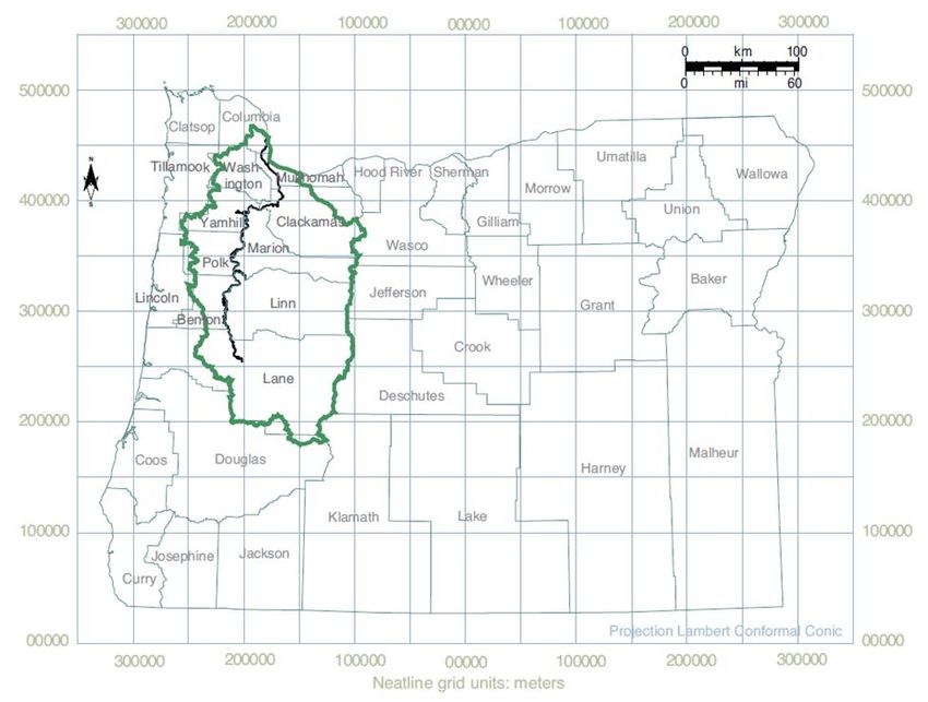
The 187-mile Willamette River initiates near Eugene, Oregon, runs through Portland,
Oregon, and terminates at the Columbia River estuary, the largest f luvially d ominated
estuary in the Pacif ic Northwest. Lying in the Willamette Valley, the river drains an area
of 11,200 mi2 in the Willamette River Basin (Figure 6). With an average width of 75 miles,
10 | January 29, 2021Preliminary Navigation Study
Multnomah County | Earthquake Ready Burnside Bridge Project
the Willamette River Basin accounts f or 12 percent of Oregon state area, 13 of 36
Oregon state counties, and 70 percent of Oregon state population (FEMA 2010, PNERC
2002, USACE 2017, Wherry 2018).
Figure 6. Willamette River Basin (green), Willamette River (black), and Oregon Counties
Source: Pacific Northwest Ecosystem Research Consortium (PNERC) 2002
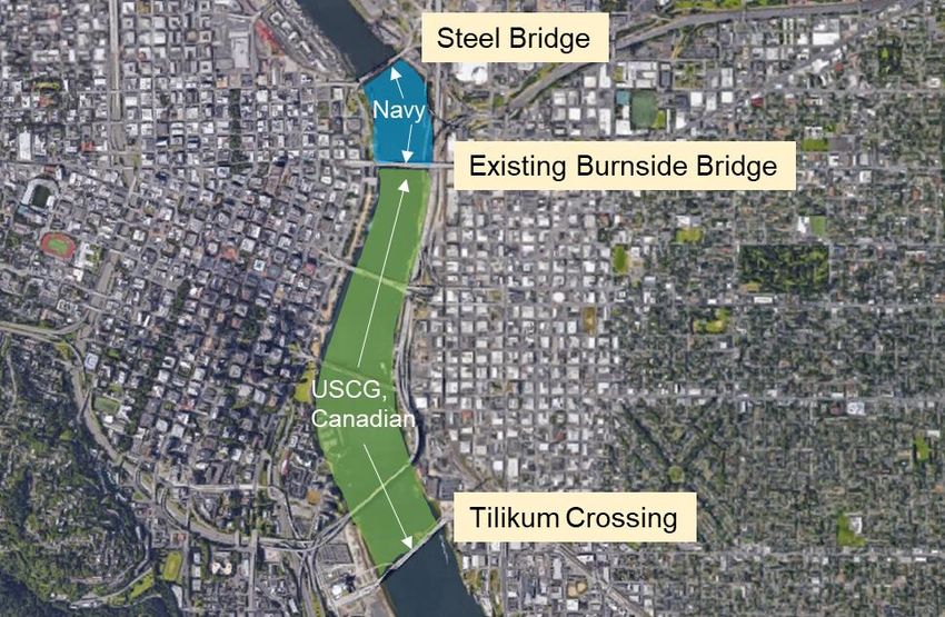
The waterway layout in the vicinity of the Burnside Bridge impacts navigation. The
Burnside Bridge is situated just south of a bend in the Willamette River adjacent to
Downtown Portland (Figure 7). River users must navigate f our bridges in close proximity
near this river bend.
January 29, 2021 | 11Preliminary Navigation Study
Multnomah County | Earthquake Ready Burnside Bridge Project
Figure 7. Willamette River Waterway Layout in Vicinity of Burnside Bridge
The combination of waterway layout and bridge proximity increases the challenge of river
navigation when transiting the Burnside Bridge. As described by Advanced American
Construction, Inc., passability is “in relation to other bridges. Ultimately that’s what you
have to align with.” Additionally, the Columbia River Pilots noted that “narrowing the
approach on Burnside would make the approach to Steel Bridge even more dif f icult ”
(Appendix C).
2.2.2 Hydrology and Waterway Natural Flow
In the downstream portion of the Willamette River, f loodplains are narrow, the river
gradient is low, and the backwatering ef f ect of the Columbia River is dominant (PNERC
2002). Flooding near Portland is linked in the spring to the Columbia River Basin
snowmelt f reshet, and in the winter to rainstorms and high f lows in the Columbia and
Willamette Rivers (FEMA 2010).
At Willamette Falls (WRM 26), the 1 percent annual exceedance probability (AEP)
regulated f low is 11,000 m3/s (Wherry 2018).
This study f ocuses on the downstream, or northern, portion of the Willamette River
between Willamette Falls (WRM 26) and the Columbia River (WRM 0). This portion of
the river f lows through a basalt trench f ormed by a series of lava f lows that pre-date the
uplif t of the northern Cascade Mountain Range. It has undergone little geomorphic
change over the last 150 years; river channels and islands have remained relatively
consistent (PNERC 2002).
12 | January 29, 2021Preliminary Navigation Study
Multnomah County | Earthquake Ready Burnside Bridge Project
Discharge at the proposed bridge is derived from USGS Station 14211720 Willamette
River at Portland, OR (Table 9, USGS, n.d.).
Table 9. Willamette River Discharge
Annual Mean Discharge, Average 33,312 ft.3/sec 1973 to 2017
Annual Mean Discharge, Minimum 21,170 ft.3/sec 1992
Annual Mean Discharge, Maximum 57,490 ft.3/sec 1996
2.2.3 Waterway Depth and Elevation Fluctuations
Willamette River Basin Datums
Three datums are commonly ref erenced throughout the Willamette River Basin (NOAA,
CREOFS, n.d., and Datums, n.d.):
• National Geodetic Vertical Datum of 1929 (NGVD 29). This vertical control datum
was originally established in 1929 as the Sea Level Datum of 1929, and re-
established with its current name in 1973. It was developed f rom the observed
heights of mean sea level at 26 tide gauges throughout the U.S. and Canada. In
1992, this datum was superseded by the North American Vertical Datum of 1988.
• North American Vertical Datum of 1988 (NAVD 88). This vertical control datum
was established in 1991, and developed f rom the height of the primary tidal bench
mark at a single station: Father Point/Rimouski, Quebec, Canada.
• Columbia River Datum (CRD). This non-tidal, def ined-gradient datum along the
Columbia River (between miles 23 ad 145) and the Willamette River (f rom WRM 0 to
WRM 27). USACE f irst established this low-water ref erence plan during a 1912
observational study. The zero ref erence f or CRD lies below average low water, but
not at the lowest record. CRD was historically redef ined with respect to f irst
NGVD 29, and then NAVD 88.
The City of Portland Datum and Portland River Datum also appear on some survey
documents, but they are not used in this study.
Tidal and Flood Elevations
The United States Geological Survey (USGS) and National Oceanic and Atmospheric
Administration (NOAA) historically maintained three tid al stations in the downstream
portion of the Willamette River (Table 10).
January 29, 2021 | 13Preliminary Navigation Study
Multnomah County | Earthquake Ready Burnside Bridge Project
Table 10. Willamette River Tidal Stations
Date Date
Agency Station ID Location Datum
Established Removed
NOAA 9439221 Morrison Bridge 16 Oct 1940 28 Jan 2009 7.03 ft. abv
NAVD 88
USGS 14211720 Morrison Bridge 1 Oct 1988 - 5.01 ft. abv
NAVD 88
USGS 14207770 Willamette Falls 1 Oct 2007 - 3.51 ft. abv
NAVD 88
Source: NOAA, Station ID 9439221; USCG 1420770, 14211720, n.d.
Figure 8 displays tidal and f lood elevations in the Willamette River at Morrison Bridge
with respect to NAVD 88. Tidal data f rom NOAA Station 9439221 Morrison Bridge
provides the assumed tidal characteristics f or Mean Higher High Water (MHHW), Mean
Low Water (MLW), and Mean Lower Low Water (MLLW). Ordinary High Water (OHW)
stage is derived f rom the USACE at the proposed bridge (USACE 2017). Flood
characteristics are provided by a 2010 Federal Emergency Management Agency (FEMA)
f lood insurance study (FEMA 2010).
Figure 8. Expected Tidal and Flood Elevations at Morrison Bridge (WRM 12.8)
Source: NOAA Station ID 9439221, n.d.; FEMA 2010
14 | January 29, 2021Preliminary Navigation Study
Multnomah County | Earthquake Ready Burnside Bridge Project
OHW is the water level that Portland USACE uses f or planning purposes, based on the
high water mark naturally demarcated by vegetation along the river bank . OHW was
justif ied as a basis f or the worst-case river level stage f or the purposes of required
navigational clearance in the most recent navigation study in the area that was accepted
by the USCG (Tilikum Crossing).
Up to 13 f eet of tidal f luctuation between OHW and MLLW is expected . Flood f luctuations
f ar exceed tidal f luctuations. A flood with a 10 percent chance of occurring in any year
(10-year f lood) exceeds MLLW elevation by 18 f eet. A f lood with a 1 percent chance of
occurring in any year (100-year f lood) exceeds MLLW elevation by 25 f eet. (FEMA
2010).
Flood Control
Four f lood control types are identif ied in the Willamette River Basin (FEMA 2010,
PNERC 2002, USACE 2017):
• Willamette Valley Project. Between 1941 and 1969, the U.S. Congress authorizing
the Willamette Valley Project through a series of Flood Control Acts . Under these
Acts, USACE constructed thirteen dams, reservoirs, and af f iliated inf rastructure in
the Willamette River Basin with 1.6 million acre-f eet f lood storage capacity. This
system has not only reduced f lood elevation on the Columbia and Willamette Rivers,
but also aided navigation, irrigation, hydropower, water supply, pollution abatement,
f ish and wildlif e, and recreation.
• Revetments. For more than a century, the Willamette River has been redirected and
its erosion slowed by placing large stones in riprap, wing def lectors, and levees.
USACE constructed and manages approximately half of the 96 miles of revetments.
While revetments may mitigate f loods and erosion at the installation site, they can
simultaneously expedite f loods and erosion in other areas.
• Seawall. The Portland Seawall is a concrete wall extending f rom the Steel Bridge
(WRM 12.1) to Hawthorne Bridge (WRM 13.1). Built in 1928, the railing of the wall
extends above 500-year f lood levels. However, f loods may still circumvent the
seawall downstream of the Steel Bridge.
• Nonstructural measures. In April 1972, Ordinance No. 134486 National Flood
authorized the participation of the City of Portland in the FEMA National Flood
Insurance Program. Under this resolution, building permit applications and
subdivision proposals are reviewed f or f lood saf ety.
2.2.4 Maintenance Dredging
Maintenance dredging last occurred in 2011, when the channel at WRM 1+50 to WRM
2+52 was dredged to -40 f t CRD plus overdredge. There are currently maintenance
dredging operations being planned at WRM 1+50 to 2+52 and WRM 9+40 to 10+17.
Responsibility for maintaining the channel f rom the Broadway Bridge (WRM 11.6) to the
Ross Island Bridge (WRM 14.0) is delegated to the Port of Portland 2. There has been no
2
Source: Yballe, D. (comments on 1/31/20 draft version of this report) [US Army Corps of Engineers,
Portland District], February 28, 2020
January 29, 2021 | 15Preliminary Navigation Study
Multnomah County | Earthquake Ready Burnside Bridge Project
recent channel maintenance in this stretch and none is currently planned 3. See
Section 2.2.6 f or a description of the f ederal navigation channel.
2.2.5 Guide Clearances
The USCG has established Guide Clearances f or many navigable waterways in the
United States (USCG, n.d.). Bridges and causeways that satisf y these navigational
clearances are viewed f avorably during the bridge permitting process. Table 11 provides
the USCG Guide Clearances f or the Willamette River.
Table 11. Willamette River Guide Clearances
Clearance
River
Description Bridge Type
Segment
Horizontal Vertical
Mouth to Broadway 211 ft. abv NAVD
WRM 0 – 11.6 Fixed 1,000 ft.
Bridge 88
171 ft. abv NAVD
Fixed 500 ft.
WRM 11.6 – Broadway Bridge to 88
14.0 Ross Island Bridge 71 ft. abv NAVD
Movable 250 ft.
88 (closed)
WRM 14.0 – Ross Island Bridge to
- None None
25.5 Abernethy Bridge
Source: USCG, n.d.
Existing bridges are not necessarily required to satisf y USCG Guide Clearances. Two of
f our bridges in the f irst segment (WRM 0 – 11.6) do not satisf y vertical Guide Clearances
(St John’s Railroad Bridge, and the Fremont Bridge). Three of six bridges in the second
segment (WRM 11.6 – 14.0) do not satisfy vertical Guide Clearances (Marquam Bridge,
Tilikum Crossing Bridge, and Ross Island Bridge). Future bridges, however, are
encouraged to achieve these guide clearances, if practicable.
2.2.6 Channel and Waterway Alignment
The Willamette River Navigation Channel f rom WRM 0.0 to the Broadway Bridge
(WRM 11.6) is authorized to -43 f eet CRD plus overdredge. The channel has a depth of
40 f eet, and widths ranging f rom 600 f eet to 1,900 f eet. (USACE Portland District, 2003).
From the Broadway Bridge (WRM 11.6) to the Ross Island Bridge (WRM 14.0), t he
authorized f ederal navigation channel is 30 f eet CRD . The authorized channel width is
300 f eet, however it is not currently delineated; thus, this study assumes no restrictions
on vessel access between riverbanks 2.
Table 12 summarizes the navigation channels on the Willamette River.
3
Source: Super, G. (phone call) [Port of Portland], April 20, 2020.
16 | January 29, 2021You can also read