Preparatory Study on Ecodesign and Energy Labelling of Batteries under FWC ENER/C3/2015-619-Lot 1 - TASK 4 Technologies - For Ecodesign and Energy ...
←
→
Page content transcription
If your browser does not render page correctly, please read the page content below
Preparatory Study on Ecodesign and
Energy Labelling of Batteries under
   FWC ENER/C3/2015-619-Lot 1

                         TASK 4
    Technologies – For Ecodesign and Energy Labelling

             VITO, Fraunhofer, Viegand Maagøe

April 2019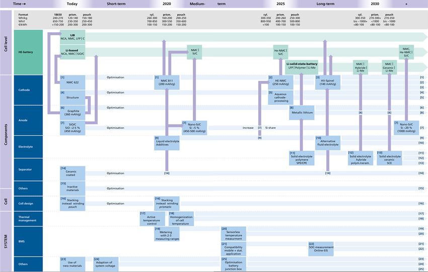
Preparatory study on Ecodesign and Energy Labelling of batteries

Study team leader: Paul Van Tichelen
       VITO/Energyville – paul.vantichelen@vito.be

Key technical expert:
       Tim Hettesheimer,
       Axel Thielmann,
       Christoph Neef

Authors of Task 4:
      Tim Hettesheimer - Fraunhofer ISI (Lead author)
      Axel Thielmann - Fraunhofer ISI
      Christoph Neef - Fraunhofer ISI
      Antoine Durand - Fraunhofer ISI

Quality Review:           Jan Viegand - Viegand Maagøe A/S

Project website:          https://ecodesignbatteries.eu/

Version history:
Version 1: Version made available in December 2018 for the Stakeholders to comment
 and discussion in the stakeholder meeting.
Version 2 (this version):
- is a review based on the input from the stakeholder comments which resulted mainly
  in a reviewed description of the technology itself and the life cycle stages
- includes several updates on the text and additional figures
- a revised version of the BOM according to the stakeholder comments
- includes some recommendations based on the findings of this task at the end of the
  report.

EUROPEAN COMMISSION
Directorate-General for Internal Market, Industry, Entrepreneurship and SMEs
Directorate Directorate C – Industrial Transformation and Advanced Value Chains
Unit Directorate C1
Contact: Cesar Santos
E-mail: cesar.santos@ec.europa.eu

European Commission
B-1049 Brussels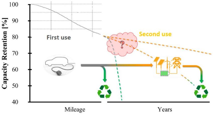
Preparatory study on Ecodesign and Energy Labelling of batteries

             Europe Direct is a service to help you find answers
               to your questions about the European Union.
                                   Freephone number (*):
                                00 800 6 7 8 9 10 11
    (*) The information given is free, as are most calls (though some operators, phone boxes or hotels
       may charge you).

LEGAL NOTICE

This document has been prepared for the European Commission however it reflects the views only of the authors, and the
Commission cannot be held responsible for any use which may be made of the information contained therein.

This report has been prepared by the authors to the best of their ability and knowledge. The authors do not assume liability
for any damage, material or immaterial, that may arise from the use of the report or the information contained therein.

© European Union

Reproduction is authorised provided the source is acknowledged.

More information on the European Union is available on the Internet (http://www.europa.eu).

Luxembourg: Publications Office of the European Union, 2019

ISBN number [TO BE INCLUDED]

doi:number [TO BE INCLUDED]

© European Union, 2019

Reproduction is authorised provided the source is acknowledged.

3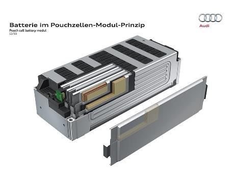
Preparatory study on Ecodesign and Energy Labelling of batteries

Contents

4.          TASK 4: TECHNOLOGIES........................................................................9
4.1.        Subtask 4.1 - Technical product description ..............................................10
4.1.1.      Existing products .......................................................................................10
4.1.1.1.    Description of the key components of a battery system ............................10
4.1.1.2.    Key components on cell level - Elements of a cell and cell formats .........11
4.1.1.3.    Cell housing and cell formats ....................................................................14
4.1.1.4.    Key components on module level ..............................................................15
4.1.1.5.    Key components on system level ...............................................................16
4.1.2.      Discussion on battery technology improvement (design) options .............17
4.1.2.1.    Cathode ......................................................................................................20
4.1.2.2.    Anode .........................................................................................................24
4.1.2.3.    Separator ....................................................................................................27
4.1.2.4.    Electrolyte ..................................................................................................28
4.1.2.5.    Cell design and cell formats .......................................................................31
4.1.2.6.    Battery management system (BMS) ..........................................................33
4.1.2.7.    Thermal management.................................................................................35
4.1.2.8.    Housing and additional components ..........................................................37
4.1.3.      Overview of the improvement design options and classification
            regarding BAT and BNAT and expected timeline ....................................39
4.2.        Subtask 4.2 - Production, distribution and end-of-life...............................41
4.2.1.      Product weight and Bill-of-Material (BOM) .............................................41
4.2.2.      Assessment of the primary scrap production during sheet metal
            manufacturing ............................................................................................50
4.2.2.1.    Production process of a LiB .......................................................................50
4.2.2.2.    Energy consumption of battery production................................................54
4.2.2.3.    Improvement options on side of the battery production ............................55
4.2.3.      Packaging materials ...................................................................................57
4.2.4.      Materials flow and collection effort at end-of-life .....................................61
4.2.4.1.    Raw material sourcing ...............................................................................61
4.2.4.2.    Second-life applications .............................................................................64
4.2.4.3.    Recycling ...................................................................................................68
4.2.5.      Environmental impact of li-ion batteries production .................................75
4.3.        Subtask 4.3 - Recommendations ................................................................76
5.          LITERATURE ...........................................................................................78

4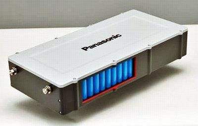
Preparatory study on Ecodesign and Energy Labelling of batteries

ABBREVIATIONS

Abbreviations    Descriptions
ADR              European Agreement Concerning the International Carriage of
                 Dangerous Goods by Road
Al               Aluminum
BAT              Best Available Technologies
BC               Base case
BEV              Battery Electric Vehicle
BJB              Battery junction box
BMS              Battery Management System
BNAT             Best Not-yet Available Technologies
BOM              Bill-of-Material
CED              Cumulative energy demand
CMC              Carbon methyl cellulose
CNT              Carbon nanotube
Co               Cobalt
CPE              Composite polymer electrolytes
CRM              Critical Raw Materials
DEC              Diethyl carbonate
DMC              Dimethyl carbonate
DOD              Depth of Discharge
EC               European Commission
EC               Ethylene carbonate
EMC              Ethyl methyl carbonate
EoL              End-of-life
EPTA             European Power Tool Association
ESS              Electrical Energy Storage Systems
EU               European Union
EV               Electric Vehicle
Fe               Iron
FU               Functional Unit
GWP              Global Warming Potential
HE               High-energy
HEV              Hybrid Electric Vehicle
HV               High-voltage
IATA             International Air Transport Association
IMDG             International Maritime Dangerous Goods Code
ISO              International Organization for Standardization
LCA              Life Cycle Assessment
LCO              Lithium-ion Cobalt Oxide
LCV              Light commercial vehicles
LFP              Lithium-Ion Phosphate
Li               Lithium
LIB              Lithium ion battery
LMNO             Lithium-Ion Manganese Nickel Oxide
LMO              Lithium-Ion Manganese Oxide
LMP              Lithium-Metal-Polymer

5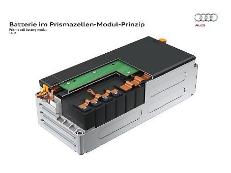
Preparatory study on Ecodesign and Energy Labelling of batteries

LTO              Lithium-Ion Titanate Oxide
LVD              Low Voltage equipment
MEErP            Methodology for Ecodesign of Energy related Products
Mn               Manganese
NCA              Lithium Nickel Cobalt Aluminium
Ni               Nickel
NiCd             Nickel-Cadmium
NiMh             Nickel-Metal hydride
NMC              Lithium-ion Nickel Manganese Cobalt Oxide
P                Phosphor
Pb               Lead
PC               Passenger car
PE               Polyethylene
PHEV             Plug-in Hybrid Electric Vehicle
PP               Polypropylene
PV               Photovoltaic
PVD              Physical vapour deposition
R&D              Research and Development
SASLAB           Sustainability Assessment of Second Life Application of Automotive
                 Batteries
SEI              Solid-electrolyte interphase
Si               Silicon
SOC              State of Charge
SPE              Solid polymer electrolyte
TIM              Thermal interfacial material
TRL              Technology Readiness Level
UN               United Nations
UNECE            United Nations Economic Commission for Europe
WEEE             Waste electrical and electronic equipment
ZVEI             Zentralverband Elektrotechnik- und Elektronikindustrie e. V.

6
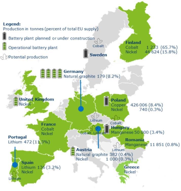
Preparatory study on Ecodesign and Energy Labelling of batteries

List of Figures:
Figure 1: Schematic overview of the key components of a battery system after
(Hettesheimer 2017) .......................................................................................................... 11
Figure 2: Exemplary structure of a battery cell (Hettesheimer 2017) ................................ 11
Figure 3: Possible cell formats: pouch, cylindrical and prismatic cell format ..................... 15
Figure 4: Exemplary module structures for different cell formats ...................................... 16
Figure 5: Definition of improvement options (Thielmann et al. 2017)................................ 19
Figure 6: Distribution of cell chemistries within the different Base Cases (based on Pillot
2017; Hill et al. 2018 and own assumptions) ..................................................................... 43
Figure 7: Weight distributions given in literature ............................................................... 45
Figure 8: Analyse of the weight distributions by different system capacities, cell chemistries
and applications (own analyse based on Nelson et al. 2017)............................................. 46
Figure 9: Weight distribution of a virtual product for the applications (own assumptions
based on Figure 7 and Figure 8) ......................................................................................... 47
Figure 10: Share of materials in modules due to different cell formats (own assumptions
based on internal data) ...................................................................................................... 47
Figure 11: Weight distribution of the packaging for a virtual product ................................ 48
Figure 12: Approach for defining a virtual product (on cell level) ...................................... 50
Figure 13: Approach for defining a virtual product on the battery systems level .............. 50
Figure 14: Exemplary lithium ion battery manufacturing process (Hettesheimer et al. 2013)
 ........................................................................................................................................... 51
Figure 15: Cumulative energy demand at battery pack level for different cell chemistries
(based on Peters et al. 2017) ............................................................................................. 55
Figure 16: Flow-chart to determine the appropriate packaging (ZVEI & EPTA 2018) ......... 59
Figure 17: End-of-life options for LiB (based on European Environment Agency 2018) ..... 61
Figure 18: Mine production and potential of battery raw materials, and battery plants in the
EU11 (European Commission 2018) ................................................................................... 62
Figure 19: Options after the first-life of the battery (Podias et al. 2018) ........................... 65
Figure 20: Different possible recycling routes (based on Friedrich and Peters 2017) ........ 68
Figure 21: GHG impacts (per kg battery) from the production of Li-ion batteries for different
cell chemistries (Hill et al. 2018) ........................................................................................ 75
Figure 22: Potential changes in battery manufacturing greenhouse gas emissions by
different measures (Hall and Lutsey 2018) ........................................................................ 76

7
Preparatory study on Ecodesign and Energy Labelling of batteries

List of Tables:
Table 1: Properties of different cathode materials (Rosina 2016) ...................................... 13
Table 2: Expected timeline for the market entry of the improvement options .................. 40
Table 3: Key parameters of market products used to build the Base case ........................ 42
Table 4: Specifications and BOM of the considered cells as database for calculating the base
cases (mainly based on information from (Takeshita et al. 2016, 2018) ........................... 44
Table 5: Overview of the key parameters for battery systems used in reviewed studies .. 45
Table 6: BOM for the defined Base Cases (own calculation) .............................................. 49
Table 7: Transport issues (Example) (ZVEI & EPTA 2018) .................................................. 60
Table 8: Production and sourcing of primary battery raw materials (European Commission
2018) .................................................................................................................................. 63
Table 9: Relative supply risk indicator for different raw materials (based on Thomas et al.
2018; Helbig et al. 2018) .................................................................................................... 64
Table 10: Influence of the DOD on the cycle life (Battery University 2018) ....................... 64
Table 11: Estimated recoverable capacity when storing Li-ion for one year at various
temperatures (Battery University 2018) ............................................................................ 65
Table 12: Qualitative assessment of different recycling routes (based on Friedrich and
Peters 2017) ....................................................................................................................... 69
Table 13: Recycling efficiency for specific materials (based on Diaz et al. 2018) .............. 70
Table 14: Recycling efficiency of recycling processes (Lebedeva et al. 2016; Hill et al. 2018)
........................................................................................................................................... 70
Table 15: Overview of recycling companies and corresponding recycling processes (Romare
and Dahllöf 2017; Lebedeva et al. 2016) ........................................................................... 71
Table 16: LCA results for different recycling stages (Romare and Dahllöf 2017) ............... 74

8
Preparatory study on Ecodesign and Energy Labelling of batteries

4.                 Task 4: Technologies
Summary
Battery systems are built up on a range of cells technologies, which are evolving rapidly in
order to improve efficiency, energy density, performance or reliability. Furthermore,
improvements on component side as e.g. the housing or BMS allow a broad spectrum of
different combinations to design a battery system. Anyhow, taking as a reference year
2018, the Lithium-Ion technology can be expected a suitable base case, for applications as
battery-electric passenger car (PC BEV), plug-in-hybrid passenger car (PC PHEV), battery-
electric light commercial vehicles (LCV BEV), battery-electric medium-duty tractor unit
(Truck BEV), plug-in-hybrid heavy-duty tractor unit (Truck PHEV), Residential storage and
Grid stabilization.
Furthermore, lately a number of competing lithium-ion cell chemistries and designs have
subsequently been commercialized and could be candidates for Best Available Technologies
(BAT). These comprise cells, which use cathodes, with a higher content of Ni or which are
renouncing on using a blend of materials. While e.g. for the anode a percentage of silicon
is added to the former pure graphite anode. However, new cell technologies are evolving
as for example high voltage spinel, high energy NMC (Nickel Manganese Cobalt Oxide) or
Ni-rich cathode materials as well as solid-state batteries1. Those, also not yet available on
the market can be considered for Best Not-yet Available Technologies (BNAT).
Current batteries on the market are not designed for circularity, meaning easy to
disassemble, repair, refurbishment and recycling. They are not considered to be easily
opened and usually designed to be only opened at end of life by mechanical intervention.
Such irreversible design severely limits not only the potential for repair/refurbishment
potentials, but also the recovery of valuable materials or the reuse of components. There
are only currently limited examples of module design to support ease of disassembly or
dismantling for recycling.
Despite of the outstanding needs from recyclers and of the advancements in technological
research, there are currently a clear lack of business incentives for manufacturers to
implement design-for-circularity.
In summary, the following Base cases (BC), BAT and BNAT were identified2. The cell
technology is proposed as starting point for defining the combinations because it is
fundamental to achieving performance improvements. Therefore, it has to be considered
that we are dealing with a flexible product, consisting of different cell chemistries.
      •   The Base Case e.g. (BC1) is an average performing EV battery system for BC1.
      •   A BAT Case is combing one or more measures as listed in Table 2 (see chapter 4.1.3)
          for "Today"
              o    Higher share of Ni (in case of NMC but nor already NMC 811 Ni-rich).
              o    Silicon added graphite anode and an increased layer thickness compared to previous
                   versions of the cells.
              o    Reduced thickness of the separator

1   Other than LMP
2   An in depth analysis of the base cases will be conducted in Task 5

9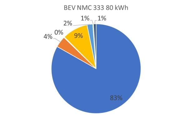
Preparatory study on Ecodesign and Energy Labelling of batteries

            o    Optimization of inactive materials: Reduction of inactive materials such as binders,
                 or the reduction of current collector thickness.
            o    Housing improvements regarding isolation, weight and more.
     •   BNAT- is a battery system based on future improvements (see 4.1.3), thus the BNAT
         is expected to include battery technologies as:
            o    All-solid-state batteries
            o    High-voltage spinels or
            o    High energy NMC

4.1.             Subtask 4.1 - Technical product description
Task 4 provides a technological description of the products in scope of the study. Thus, it
serves two different purposes: On the one hand it is intended to inform the policymakers
and stakeholders about the product and its components from a technical perspective, on
the other hand it serves to define the Base Cases and also works towards the definition of
Best Available Technology (BAT) and state-of-the-art Best Not yet Available Technology
(BNAT). While the Base Case represents an average product on the market today in terms
of resources efficiency, emissions and functional performance, the BAT and BNAT will also
be assessed in terms of environmental improvement potential. The BAT represents the best
commercially available product with the lowest resources use and/or emissions. The BNAT
represents an experimentally proven technology that is not yet brought to market, e.g. it is
still at the stage of field‐tests or official approval. The assessment of the BAT and BNAT
provides the input for the identification of the improvement potentials in Task 6. The data
for the base cases will serve as input for Task 5.

4.1.1.           Existing products

4.1.1.1.         Description of the key components of a battery system
A battery system builds up from different subcomponents, which are depicted in the
following Figure 1. The electrode is thereby often seen as the smallest joint unit within a
battery system.
A cell contains, depending on its final purpose, a certain number of electrodes. Since, the
energy of a single cell is in most cases not sufficient for performing the function of a product;
several cells are connected in parallel or in series to form modules. The individual modules
are then provided with a mechanical support structure and connectors. Several modules in
a row or in parallel are then combined again to form a battery system. The number and
type of connected cells and modules finally depends on the desired operating mode of the
application (Ketterer et al. 2009).

                                                                              Battery System

10
Preparatory study on Ecodesign and Energy Labelling of batteries Figure 1: Schematic overview of the key components of a battery system after (Hettesheimer 2017) In order for the cell or battery system to fulfil its intended function safely and optimally, further additional components are required on battery system level. The housing with the associated cooling system and battery management system shields the partially sensitive active and passive components of the accumulator system (BMS) from harmful environmental influences (water, dust, etc.) (Rahimzei et al. 2015). After giving this short overview of the structure of a battery system, a detailed description of the mentioned key components will be given in the following. 4.1.1.2. Key components on cell level - Elements of a cell and cell formats The components of a battery cell that are needed to fulfil its function are the cathode, anode, separator, electrolyte and the housing as well as further safety components. The functional structure of a cell and of the key components is exemplarily displayed in the following Figure 2. The components will be briefly described while an outlook of their future improvement potentials will be given later. Figure 2: Exemplary structure of a battery cell (Hettesheimer 2017) Cathode The cathode (positive electrode) consists of mixed oxides applied to an aluminium foil (or aluminium current collector). The cathode material consists of the active material, a polymeric binder which is usually polyvinylidene difluoride and a conductive additive as carbon black. The cathode materials currently used are lithium nickel cobalt manganese oxide (NMC), lithium nickel cobalt manganese oxide (NCA) or lithium iron phosphate (LFP). In addition, these cathode materials are also mixed with lithium manganese oxide (LMO) to form LMO-NCM and LMO-NCA (Thomas et al. 2018; Rahimzei et al. 2015). Manganese spinel oxides (LiMn2O4, LMO for short) are characterized by high safety in the event of overcharging, high thermal stability and low material costs. Their specific capacity is about 120 mAh/g. Difficulties arise due to undesired side reactions, like Mn dissolution, which lead to a reduction in service life. Lithium nickel cobalt aluminium oxide (LiNiCoAlO2, NCA for short) has a high power density and long service life as well as a high specific capacity of 160-180 mAh/g. Disadvantages are the low thermal stability as well as high material costs, whereby depending on the development of nickel and cobalt prices there is still price reduction potential. Compared to NCA, lithium nickel manganese cobalt oxide (LiNiMnCo2, NMC for short) is characterized by higher thermal stability and lower costs, while the specific capacity of 150 mAh/g (NMC 111) is somewhat lower. Compounds with a higher share of Ni as NMC 532 are 11
Preparatory study on Ecodesign and Energy Labelling of batteries

achieving a higher energy density of somewhat 170 mAh/g. Furthermore, there are also
chemistries with still higher energy capacities available and under development, which will
be described later on.
The lithium iron phosphate batteries (LiFePO4, LFP for short) have a higher chemical
stability than the oxides. This ensures a long service life and safety. It is also
environmentally friendly and relatively inexpensive. The specific capacity is approx. 160
mAh/g and thus roughly corresponds to that of NMC, but at lower voltage of 3.3 V
(Anderman 2013; Mock 2010; Wallentowitz and Freialdenhoven 2011; Peters et al. 2013).
The following table provides a summary of the properties of different cathode materials.

12
Preparatory study on Ecodesign and Energy Labelling of batteries

Table 1: Properties of different cathode materials (Rosina 2016)

                LMO              LFP               NMC              LTO              NCA

 Nominal        3.80 V           3.30 V            3.65 V           2.3 V            3.60 V
 voltage

 Charge         4.20 V           3.60 V            4.20 V           2.7              4.20 V
 limit
 (Vmax)

 Cycle life     >1,000           >2,000            1,000 -2,000     >5,000           2,000 -3,000

                                                                    Up to 15,000+

 Specific       Medium/high      Medium/high       High             High             High
 power
 (W/kg)

 Thermal        Fairly stable    Stable            Fairly stable    Stable           Least stable
 stability

 Cost           Medium           Medium-to-        Medium-to-       High             Medium-to-
                                 high              high                              high

 Pros

                •Cost, safety,   •Safety           •Energy          •Safety          •Energy
                power                              density                           density
                                 •Materials                         •Cycle time
                                 cost              •Range      of                    •Lifetime
                                                   charge
                                 •Life
                                 expectancy

 Cons

                •Lifetime        •Low              •Safety          •Low voltage     •Cost
                                 temperature
                                                   •Cost            •Energy          •Safety
                                 performance
                                                                    density
                                                                                     •Low thermal
                                 •Processing
                                                                                     stability
                                 cost

 Supplier       LG     Chem,     BYD,      A123,   Panasonic,       Leclanché,       Panasonic,
                NEC,             Saft              Kokam, Saft      Toshiba,         Saft
                Samsung                                             Microvast, ATL
                SDI, AESC

Anode

13
Preparatory study on Ecodesign and Energy Labelling of batteries The anode (negative electrode) of the typical li-ion cell consists of a copper foil (or copper current collector) and graphite or a lithium alloy material. Natural or synthetic graphite anodes are currently the most common choice because of their low electrode potential and low volume expansion when Li+ ions are intercalated. For high performance and safety requirements, lithium titanate as an additional option is also available, going along with disadvantages in terms of cost and energy density. Common binders here are: e.g. carbon methyl cellulose (CMC) or polyacrylic acid (Rahimzei et al. 2015). In the case of an all solid Lithium-Metal-Polymer (or LMP®) cell, the anode is made of a thin film of metallic lithium that serves simultaneously as an electrochemical anode and a current collector Separator The LIB separator isolates the two electrodes from each other in order to prevent a short circuit and to prevent malfunctions. The pores of the separator are filled with the electrolyte in liquid or gel form. The separator is mostly made of a porous plastic composite of polyethylene (PE) and polypropylene (PP). But PP/PE has the disadvantage of a low melting temperature (approx. 165 °C). However, another choice to enhance thermal resistance, are ceramic or ceramic coated separator. In addition, nonwovens and glass fibre separators are used in research (Rahimzei et al. 2015). For the LMP technology, the separator is a thin polymeric film that contains the lithium salt. It serves simultaneously both the purposes of separator and electrolyte. Electrolyte Electrodes are wetted by liquid electrolyte, which enables Li-ion transport. The electrolyte is required to be stable electrically in a typical LIB voltage range from 0 to 4.5 V and must have a high ion conductivity over a wide temperature range (from -40 °C up to +80 °C). Usually a liquid electrolyte consists of mixture solutions such as ethylene carbonate (EC), diethyl carbonate (DEC), dimethyl carbonate (DMC), and ethyl methyl carbonate (EMC) dissolved lithium salts (e.g. LiPF6). Besides the most common fluid electrolyte, also polymer electrolytes are used. Since it is not possible for the polymers to escape, the use of stiff containers is not necessary and thus a lighter construction possible. The disadvantage, however, is the lower conductivity (Rahimzei et al. 2015; Thomas et al. 2018). 4.1.1.3. Cell housing and cell formats Li-ion cells differ not only in the cell chemistry used, but also in their cell geometries, which directly influence the shape of the cell housing. Currently, three different cell formats are used in practice: the cylindrical cell, the pouch cell and the prismatic cell. The basic elements of a cell described in Figure 2 represent the starting point of any cell geometry. Depending on the shape of the cell housing, the cell is inserted differently into the housing during the production step of cell assembly. While pouch cells can be stacked or wound, cylindrical and prismatic cells are usually wound. The different cell shapes as well as a cross-section (A, B & C) of the respective cells are illustrated in Figure 3. 14
Preparatory study on Ecodesign and Energy Labelling of batteries

                                                                    Zellgehäuse

         Kathode

                                                                  Aluminium
        Separator                                                 Kupfer

        Anode
                                                                  Zellgehäuse

                                                                                C
                       A
                                            +

                                 B                   B
                                            -               C
                A

         Pouch
     Flach-       cell
            bzw. Pouchzelle          Cylindrical
                                        Rundzelle cell     Prismatic
                                                           Prismatischecell
                                                                        Zelle

Figure 3: Possible cell formats: pouch, cylindrical and prismatic cell format

Depending on the geometry used, the cells have different advantages and disadvantages.
The highest volumetric energy density of cylindrical cells is due to the basic geometry
highest, but the energy density of large-format pouch cells has approached or reached a
similar energy density to that of small-format lithium-ion cells in recent years. Depending
on the module design, the cylindrical cell loses some of its advantage over the prismatic
and pouch cell at the module level due to the packing density. The stiffness of the cylindrical
cells is regarded as highest. A middle way trade-off between stability and size is the
prismatic cell, which is produced with the help of a flat winding, similar to the cylindrical
cell, and then inserted into a solid housing. With the pouch cell, the stiffness is not given by
the pouch foil and must be supplemented with a frame when inserted into the module. All
three cell shapes can be well thermally controlled. The main differences lie in the necessary
cooling effort and the possibilities of dissipating and conducting heat. The pouch cell
enables good heat dissipation via the current collectors and thus offers the best cooling
performance. In the cylindrical cell, the heat generated in the core during charging
processes can only be dissipated to a limited extent via the cell housing and the cell lid.
This disadvantage can also be seen by the prismatic cell format. These are commonly
cooled via the bottom, whereby cooling between the prismatic cells is also conceivable
(Michaelis et al. 2018; Hettesheimer et al. 2017).
The pouch cell material is an aluminium-polymer composite that forms a soft cell container.
Cylindrical and prismatic cell containers are hard cases. Cylindrical cell containers are
commonly made of steel or aluminium, while prismatic cell containers are made of polymers
or aluminium (Thomas et al. 2018).

4.1.1.4.             Key components on module level
Even though the formats of the cells are geometrically very different, the outer appearance
of a module for prismatic or a pouch cells looks quite similar (see Figure 4). The type of

15
Preparatory study on Ecodesign and Energy Labelling of batteries
components on module level are also more or less the same (also the number of the specific
components installed may differ). The cells are stored in a casing to provide them
mechanical support. The casing is thereby mostly made of aluminium or PP/PE.
Furthermore, the cells are connected on the tabs by busbars, mostly made of aluiminum.
For temperature, regulation sensors are applied and cooling channels provided. Finally,
each module has terminals to interconnect it with other modules.
Prismatic format (Source: Audi) Pouch format (Source: Audi) Cylindrical format (Source:
Panasonic)
Figure 4: Exemplary module structures for different cell formats
4.1.1.5. Key components on system level
Battery management system (BMS)
The task of the battery management system is the intelligent and optimised operation of
the battery, which increases the service life, reliability, safety and economy of the battery
system. For this reason, various sensors for temperature, voltage or current measurement
are integrated in the individual modules. The current battery condition, also known as
"State-of-Charge" (SOC), can be derived from this. And, for example in the case of EV,
conclusions can be drawn about the remaining range of a vehicle based on the SOC. A
further important task of the BMS is the charge and discharge control, since extreme
imbalances between the cell charge states could occur during the respective processes
without targeted control, which would make it impossible to charge the serially following
cells again. For optimum service life and operation, it is therefore necessary to balance the
cells. As part of safety management, short circuits are detected and battery operation is
prevented by a safety circuit. Ultimately, the battery management system is also
responsible for operating the battery in its optimum temperature range and the associated
thermal management. According to Majeau-Bettez et. al. the BMS contains electronic
circuits, software, and internal/external connections as well as wires used to operate the
battery. The BMS consists of approximately 10% printed wire (circuit) boards, 40% steel,
and 50% copper by weight (Majeau-Bettez et al. 2011a).
Thermal management
In lithium-ion batteries, thermal management has the task of controlling cell temperature
efficiently and reliably, since cell performance and ageing are strongly dependent on
temperature. Increased temperatures lead, for example, to faster degradation of the
materials and faster aging of the battery (the influence of the temperature on the lifecycle
time of battery cells is depicted in Table 10). If not controlled, higher temperatures may
16Preparatory study on Ecodesign and Energy Labelling of batteries
also lead to the triggering of a thermal runaway phenomenon3. Low temperatures can lead
to an obstruction of the current flow, as the conductivity in the electrolyte is reduced. The
system may therefore be cooled at high temperatures or heated in colder weather
conditions to ensure normal operation, optimum power output and service life. Depending
on the application, both functions can have considerable effects on the total power
consumption and thus e.g. in the case of EV on the purely electrical range. The cooling
system is either operated with air, water or other liquid coolants as e.g. Ethylene-Glycol and
is often based on a heat-pump system for also cooling or heating the cabin. Furthermore, a
TIM (Thermal interfacial material) is also used between cell and pack bottom. The cooling
system consists mainly of aluminium and partly of steel. The aluminium radiator is thereby
the main component (Rahimzei et al. 2015; Hettesheimer 2017; Ellingsen et al. 2014).
Housing and additional components
As described above, the housing shields the active and passive components of the battery
system, from harmful environmental influences. It also shields service personnel from high-
voltage components and provides temporary fire protection. It is therefore crucial for safe,
reliable and long-term operation. Especially in the case of EV traction batteries, which are
usually housed in the floor area of the vehicle, the housing may be exposed to extreme
influences such as rockfall, splashing water, etc. High mechanical stability and corrosion
resistance are therefore important. When designing the battery system for EV, attention
must be paid not only to the housing but also to internal and external mounting systems,
which must be able to withstand the sometimes high mechanical and thermal loads. In
addition, the housing, together with the components contained therein, also serves as a
stabilizing element for the body of some "Purpose Design" vehicles. Since the housing must
not only offer a high protection but has to be light weighted too, it is usually made of
aluminium and/or PP/PE.
In addition to the components mentioned above, there are numerous other elements to
complete the battery system. Busbars connect the modules together, fuses protect the
components from damage due to power surge or contactors which are isolating the battery
system from the vehicle. Closed upon completion of safety tests and opened in the event
of a crash or battery fault (Rahimzei et al. 2015).
4.1.2. Discussion on battery technology improvement (design)
options
Defining standard improvement options for battery systems in the sense as for other
products listed in the Ecodesign working plan is quite difficult. Since the LiB was
continuously improved in the past years it can already be considered as a quite mature
product and a thus standards improvement options are already state-of-the-art. Anyhow,
improvements were mostly made on the component level and regarding the efficient
operation of the battery. Potential may still be found in the engineering of the battery; e.g.
LG was able to increase the energy density of its cell by 50% without changing the chemistry
(Rosina 2016). Another major point of improvement is the reduction of passive components
and materials within the cell and the system to reduce the weight, material content and
thus reduce the environmental impact and increase the energy density. This can be reached
3 In the case of all-solid LMP cells, safety concerns are raised only when cell temperature reaches
the melting temperature of lithium at 180°C.On the contrary they need to be operated at a minimum
temperature of 60°C or more depending on the ionic conductivity that the application requires.
17Preparatory study on Ecodesign and Energy Labelling of batteries by using thinner conductors or separators, reducing the dead volume within the cell or by using lightweight components for the battery tray (Takeshita et al. 2018; Thielmann et al. 2017). However, in the upcoming years some relevant improvements are expected regarding Li- based batteries other battery types as for example non-polymeric all-solid-state batteries using metallic lithium. To define a BAT and a BNAT it is necessary to take a closer look on the future development prospective by means of the different battery components. This procedure differs from MEErP in which sections on standard improvement, BAT and BNAT are usually described in sequence. Anyhow, in this specific case for battery systems it seems rather expedient to focus on components and their improvement potentials. Based on this, subsequently a classification regarding BAT or BNAT can be made. A quite detailed outlook on the developments on component level is given by means of a roadmap from (Thielmann et al. 2017) which was developed under cooperation of German actors from science and industry and is listing mayor improvement options until the year 2030. In the following Figure 5 different technological developments and therefore improvement, options will be described for the different system components until the year 2025. The study will thus include Li-ion technologies up to generation 3b (as e.g. high voltage spinel cathodes or carbon-silicon anodes). 18
Preparatory study on Ecodesign and Energy Labelling of batteries

Figure 5: Definition of improvement options (Thielmann et al. 2017)

19
Preparatory study on Ecodesign and Energy Labelling of batteries

The classification regarding BAT and BNAT will be made after the description of the
improvement options in Table 2 (in section 4.1.3).

4.1.2.1.       Cathode4

4.1.2.1.1.     Nickel-rich materials
       Nickel-rich materials are defined as NCA with more than 80% nickel, or NMC with a
       composition of 811.
       Target and suitable cell formats
       The aim of using nickel-rich materials is, on the one hand, to dispense with Co or at least to
       reduce the Co content of the active materials. This leads to a reduction in material costs and
       resource requirements. On the other hand, it also results in an increase in material
       performance, as the electrical conductivity and Li+ diffusivity increase with an increased Ni
       content.
       Bottlenecks and solutions
       The central bottleneck for reaching market maturity is an increase in the service life of the
       materials. However, this can be achieved with a low to medium R&D effort. This is analogous
       to what has already happened with NMC materials such as 532 or 622, which now represent
       the state of the art. The reason for the reduced service life is that the surface of the nickel-
       rich materials is more reactive to the electrolyte (the unreacted residual Li source on the
       cathode surface can react with the binder to make gelation during slurry mixing process).
       Coatings, for example, can be a solution to this problem and for protection of crack and
       cation mixing causing new surface areas with structural unstable weakness of High Ni
       cathode. In addition, care must be taken during processing to ensure that the room humidity
       < 50% is maintained.
       Advantages and disadvantages
       Extremely high energy densities can be achieved with nickel-rich materials, as these
       materials or powders can theoretically be compacted almost to the level of LCO. Co-free
       materials have a higher electrical conductivity compared to NMC 111. This offers the
       possibility to save conductive additives and thus to reduce the inactive part in the cathode
       or to save further costs. Overall, the costs (per kWh) are considerably lower than with state-
       of-the-art systems or NMC 622.
       Furthermore, the approach provides an advantage with regard to resource availability,
       especially with regard to cobalt which is classified by the EC as a critical raw material 5. On
       the other hand, the higher moisture sensitivity is disadvantageous compared to NMC
       standard materials. However, this is still at a manageable level, although production costs
       are rising.
       Effort and producibility
       Producibility goes hand in hand with minor adaptations.
       Maturity and market entry (in automotive application)

4 The following improvement options are based on Thielmann et al. 2017. For this reason the source
will not be listed after each abstract.
5 https://eur-lex.europa.eu/legal-content/EN/TXT/?uri=CELEX:52017DC0490

20
Preparatory study on Ecodesign and Energy Labelling of batteries
The approach is currently still in the range of prototypes to demonstration. First samples can
however already be sampled by the customer. The market maturity for nickel-rich materials
(NMC 811) is expected to be reached around 2020. Thus, this approach can be classified as
BNAT or even BAT.
4.1.2.1.2. High-energy NMCs
High-energy (density) NMCs are lithium-rich "integrated" composite materials which can be
defined as y×Li2MnO3 (1-y)×LiMO2 M = (Ni,Mn,Co). The materials offer a theoretically high
specific capacity due to an advantageous ratio of Li to transition metal with greater than 1.
Aim and suitable cell formats
In practice, specific capacities of about 280 mAh/g are currently being achieved. The use of
high-energy NMC thus aims to increase energy density. Furthermore, high energy NMC has
a price advantage over nickel-rich materials due to its high Mn content and thus offers
additional cost reduction potential. The cell format plays no role for the use of high-energy
NMC.
Bottlenecks and solutions
Bottlenecks currently form the electrolyte availability as well as the electrolyte costs, which
are comparatively high as standard electrolytes are no longer sufficient. Furthermore, the
washing out of Mn can also impair the service life of the materials. Mn precipitates in the cell
and the cathode material degrading its performance. Particle coatings are a possibility to
prevent the washing out.
Advantages and disadvantages
There is a very high cost advantage at cell level due to the high Mn content. In addition, the
energy density is better than with NMC-111 systems, but lower than with nickel-rich
materials. The porosity of the powders, on the other hand, is similar, although the intrinsic
density is lower, which results in a lower overall density in the comparison with nickel-rich
materials. Thus high energy NMC is very advantageous in terms of cost, but not the best
solution in terms of high energy densities. The use of high-energy NMC therefore also
depends on the application and the available installation space, as well as on how much one
is dependent on the high energy densities.
Apart from this limitation, electrode balancing with the anode is problematic (different
specific capacities of cathode and anode). The anode would have to be very thick to
completely absorb the lithium from the cathode. However, this in turn limits performance
and has a negative effect on producibility. However, this aspect can be largely compensated
by the use of silicon-containing anodes.
Effort and producibility
For the use of HE-NMC a higher R&D expenditure has to be considered until the product is
finally ready for the market. This also concerns the producibility, for which a small
expenditure can be assumed.
Degree of maturity and market entry
At present the manganese-rich materials are still in the area of applied research up to
prototypes, possibly already with the customer sampling. The market entry of High Energy
NMC could take place in the year 2025 provided that all difficulties are overcome. Thus, this
approach can be classified as BNAT but may be out of time scope.
21Preparatory study on Ecodesign and Energy Labelling of batteries
4.1.2.1.3. High-voltage spinels
High-voltage spinels are lithium-manganese based oxides with a cubic structure. As nickel
doped oxides, they are classified as "5V" materials (e.g. LiMn 1.5Ni0.5O4, 4.8V against Li/Li+).
The capacity of the high-voltage spinel is approximately 140 mAh/g.
Target and suitable cell formats
The material is comparatively well available and inexpensive, which can result in cost
advantages. At the module level, a smaller number of cells can be used to achieve a high
battery voltage, thus reducing costs and increasing energy density if necessary. As with the
approaches already mentioned, the use of high-voltage spinels is independent of the cell
format.
Bottlenecks and solutions
Challenges on the way to market maturity relate in particular to electrolytes. The electrode
materials are rather unstable at this high voltage operation. Mn is dissolved into the
electrolyte and accumulate on anode surface during charging as side products by reaction
with electrolyte. The central bottleneck is therefore cathode material stability, electrolyte
stability and manganese leaching. The electrolyte stability causes the decomposition
products of the electrolyte to deposit on graphite anodes and continue to react. This
ultimately leads to cell death through dendrite formation and possible punctuation of the
separator or faster degradation the cell performance.
The electrolyte thus has a significant influence on the service life of the cell. State-of-the-art
carbonate-based electrolytes are stable up to about 4.5 V against Li/Li+. This stability must
therefore be further increased in the future, since e.g. High voltage - NMC requires a stability
up to 5 V against Li/Li+. Alternatively, coatings for these active materials are also being
developed to compensate for these disadvantages.
Advantages and disadvantages
A major advantage of using high-voltage spinels is the price advantage for the cathode
material resulting from the elimination of cobalt and the high proportion of manganese in
combination with the higher average voltage compared to standard NMC. In addition, the
energy density can be increased compared to conventional anode materials due to the
possible high potential. However, not at the level of nickel-rich materials. The disadvantage
of using high-voltage spinels is the availability of suitable electrolytes and the separator
stability.
Effort and producibility
The R&D expenditure of this approach is to be classified as high. The adjustments to
producibility are rather small or even drop-in capable.
Maturity level and market entry
HV technology is currently in the field of applied research. The market entry of high-voltage
spinels could take place between 2025 and 2030. Thus, this approach can be classified as
BNAT but is out of time scope of this study.
4.1.2.1.4. Layer thickness
With regard to the layer thickness, the optimization of the electrode is not considered from
the raw material perspective, but from the conceptual point of view of how the electrode is
designed. The charge of a cathode is currently around 40-100 Ah/m2 (coated on both sides
with aluminium). The central influencing variables for an increase in energy density are layer
thickness, porosity and tortuosity. The layer thickness influences the processability,
22Preparatory study on Ecodesign and Energy Labelling of batteries
flexibility, stability and thus also the service life of the cell. In addition, high layer thicknesses
impair the thermal conductivity of the electrode. Passivated (isolated) areas can form and
drying becomes more time-consuming. The tortuosity can be changed by microstructuring
the electrode accordingly. The porosity is currently even worse than hexagonal closest ball
packing, while the total density is already close to the limit, as the conductive additive and
the binder are still required.
Aim and suitable cell formats
The general goal of an increased layer thickness of active materials is to increase the energy
density by increasing the ratio of active to inactive materials. The approach of increased
layer thicknesses is in principle suitable for all cell formats.
Bottlenecks and solutions
The most important bottleneck on the way to an increased layer thickness is the difficult
processability. Increasing the layer thickness in order to obtain a few percent more energy
density at the system level already leads to a considerable increase in expenditure.
Accordingly, further development activities must be undertaken in the area of processability
(e.g. with regard to the drying of thick layers, powder coating processes, the handling of the
thicker electrode, for example when winding through the thicker bending radii, when filling,
...). Another bottleneck is the usable capacity of thick layers. The thickness has a negative
effect on conductivity and electrolyte distribution, which means that it takes much longer to
supply the cathode material with lithium ions or to transport them away.
Advantages and disadvantages
The advantage lies in the higher energy density due to the configuration of the electrodes
and the relatively lower proportion of inactive materials. The disadvantage, however, is the
poorer processability due to the reduced mechanical flexibility. The lower conductivity of
thick material layers leads to a poorer fast charging capacity of the cells. Furthermore, also
the available power at a low SOC will be affected. Active materials with increased layer
thickness are already on the market, and the approach is constantly being further developed.
Effort and producibility
The effort required to optimize the layer thickness can be regarded as high, the adjustments
to the producibility as low.
Maturity and market entry
The maturity is to be seen between the applied research up to the prototype. Approaches to
optimizing layer thickness are already state-of-the-art today and will continue to be pursued
and continuously improved in the future. Thus, this approach can be classified as BAT.
4.1.2.1.5. Aqueous cathode production
Aqueous cathode production describes the substitution of organic solvents by water.
Aim and suitable cell formats
The aim of using aqueous media during electrode manufacturing is to reduce manufacturing
costs and to make LIBs much more environmentally friendly by eliminating the use of organic
solvents. Aqueous cathode production is suitable for all formats.
Bottlenecks and solutions
An essential bottleneck lays in the quality of aqueous electrodes/cells and their
electrochemical performance. Many of the cell components, such as highly nickel-rich
systems or the electrolyte, are very sensitive to water. Even small residual amounts in the
23Preparatory study on Ecodesign and Energy Labelling of batteries
ppm range can have a significant effect on the performance and service life of the cells. The
processability can also still be regarded as difficult at present, as there is no corresponding
process route in place to allow the water supplied during processing to be completely dried
out of the electrodes again. One solution on the material side would be to hydrophobize the
material, which is, however, very costly.
Advantages and disadvantages
The advantage of an aqueous cathode production lays in the reduction of costs through the
saving of organic solvents and their recovery as well as in the positive environmental
aspects. While the higher energy consumption for drying and the water sensitivity of various
active materials represent a disadvantage of this process. Especially with nickel-rich and
lithium-rich materials, there is a risk of Ni and Li being washed out.
Effort and producibility
The R&D expenditure to be carried out in the field of aqueous cathode production can be
regarded as high. The adjustments to producibility are likely to be rather small.
Degree of maturity and market entry
The maturity can currently still be located in basic research. Aqueous binders are therefore
still more of a research topic. However, if material-related problems (such as cathode powder
or binders) are solved, a market launch could be possible from 2025. Thus, this approach
can be classified as BNAT but is out of time scope of this study.
4.1.2.2. Anode
4.1.2.2.1. Graphite
Natural and synthetic graphite represent the status quo as anode material and has a specific
capacity of approx. 360 mAh/g.
Aim and suitable cell formats
Until now, almost exclusively natural and synthetic graphite was used as anode materials for
LIBs, and LTO was used for special applications. The further development of energy densities
on the cathode side will in future also require new active materials on the anode side in order
to enable meaningful electrode balancing. Another driver for the increasing substitution of
graphite is the desired fast charging performance of future batteries.
The concrete aim is a further increase of the energy density, for example by increasing the
density in the electrode layers or by using graphite-containing composites.
Bottlenecks and solutions
Graphites are used today as active materials in all cell formats and currently represent the
state of the art, with no further massive improvements to the material or electrode to be
expected. With regard to thickness optimization, graphite is already close to the theoretical
limit. On the other hand, there is still development potential in the field of electrode
development, e.g. by structuring the electrode or by mixing different types of graphite,
conductive carbon black, conductive CNTs or similar.
Advantages and disadvantages
Overall, there are probably no other major advantages or disadvantages. It is an established
system. With regard to increasing the energy density, however, graphite anodes are
exhausted.
24Preparatory study on Ecodesign and Energy Labelling of batteries
Effort and producibility
The expenditure of a further optimization is to be seen as a means, since there are hardly
any optimization possibilities and further improvements are very complex. The producibility
is given.
Maturity and market entry
Today, graphite products represent the state of the art and are available on the market.
4.1.2.2.2. Si/C composites
The transition from pure intercalation materials in LIBs to mixed systems with a low content
of alloying materials such as silicon can represent a possibility to significantly increase the
specific capacity of pure carbon anodes (372 mAh/g corresponding to LiC 6). Si offers a
theoretical capacity of about 3578 mAh/g (corresponding to Li15Si4). Like graphite, the
material has very good raw material availability and low toxicity. With a redox potential of
less than 0.5 V against Li/Li +, a good compatibility to graphite-based anodes is given. Due to
the high volume change of Si in the alloy with Li of up to 300 %, electrodes with a high Si
content are exposed to strong mechanical loads. Si/C composites can partially absorb this
effect. With a mixture of 20 % Si and 80 % carbon, capacities of about 1000 mAh/g can be
achieved.
Aim
Si composites with content of < 5 % Si are already being used commercially in High Energy-
LIBs (HE-LIBs). Composites with a content of 20 % are currently in applied research (TRL 4-
5) and could, in combination with NMC, enable a gravimetric or volumetric energy density of
300-350 Wh/kg and 1000 Wh/l in the future. From the point of view of performance, possible
charge currents of 1 C - 3 C to 80 % SOC are predicted.
Bottlenecks and solutions
The change in volume leads to two types of degradation: The high mechanical load can lead
to a reduced mechanical stability of the electrode and thus to the loss of the electrical contact
of the particles. On the other hand, the volume change of the Si-particles causes a repeated
breaking-up and rebuilding of the SEI (Solid-Electrolyte Interphase). The resulting loss of
electrolyte and active material results in an irreversible loss of capacity.
Further optimization of the material and electrode architectures is necessary to cushion the
volume expansion. Approaches exist in the nanoscaling of the Si particles or a porous and
flexible structure of the composite structure. An important contribution to this is also seen in
the further development of compatible binders. Porous C-structures can absorb about 10 %
volume changes. With a volume change of 50-100 %, a strong influence on the service life
is assumed with the current state of the art.
In order to increase the stability of the SEI during cyclisation, electrolyte improvements could
contribute. Other approaches are seen in the production of coated Si particles, e.g. core/
shell structures. The lithium loss associated with the repeated build-up of the SEI could be
compensated by a partial pre-lithiation of the anode.
Advantages and disadvantages
The main advantage of Si/C composites is the increase in both gravimetric and volumetric
energy densities. As described above, a reduction in cell life seems inevitable.
Effort and producibility
The compatibility of existing electrode and cell production processes with Si/C materials is
assessed as good. The suitability of the materials is seen in particular for cylindrical and
prismatic cells, since in these formats a favourable external pressure can be applied to the
25You can also read