Project M3-a study for a manned Mars mission in 2031夡
←
→
Page content transcription
If your browser does not render page correctly, please read the page content below
Acta Astronautica 58 (2006) 88 – 104
                                                                                                             www.elsevier.com/locate/actaastro

         Project M3—a study for a manned Mars mission in 2031夡
       M. Tarabaa,∗ , K. Zwintzb,∗ , C. Bombardellic , J. Lasued , P. Roglere , V. Ruellef ,
   J. Schlutze , M. Schüßlere , S. O’Sullivang , B. Sinzigh , M. Trefferi , A. Valavanoglou j ,
                     M. Van Quickelberghef , M. Walpolek , L. Wesselsl
                           a Institut für Experimentalphysik, Universität Wien, Boltzmanng. 5, A-1090 Vienna, Austria
                             b Institut für Astronomie, Universität Wien, Türkenschanzstr. 17, A-1180 Vienna, Austria
                           c University of Padua, Centro Cisas Attivitá Spaziali, Via Venezia 15, I-35131 Padua, Italy
                      d University of Paris, Service d’Aéronomie CNRS, BP3 - Route des Gatines, F-91371 Verrieres, France
                     e Institut für Raumfahrtsysteme, Universität Stuttgart, Pfaffenwaldring 31, D-70550 Stuttgart, Germany
          f Centre Spatial de Liège, University of Liège, Parc Scientifique du Sart Tilman, Avenue du Pré-Ally, B-4031 Angleur, Belgium
                                 g University College Dublin, Department of Mechanical Engineering, Dublin 4, Ireland
                                    h Physikalisches Institut, Universität Bern, Sidlerstr. 5, CH-3012 Bern, Switzerland
               i Institut für Geophysik, Astrophysik and Meteorologie, Universität Graz, Universtitätsplatz 5, A-8010 Graz, Austria
              j Institut für Weltraumforschung, Österreichische Akademie der Wissenschaften, Schmiedlstr. 6, A-8042 Graz, Austria
                                                k Department of Physics, Trinity College, Dublin 2, Ireland
                   l Institut für Bodenökologie, GSF Forschungszentrum, Ingolstädter Landstr. 1, D-85764 Neuherberg, Germany

                          Received 14 November 2003; received in revised form 30 March 2005; accepted 4 April 2005
                                                      Available online 22 July 2005

Abstract
   This study deals with a manned mission which focuses on building an orbital station around Mars. The advantages in comparison
to direct-landing scenarios are outlined and the necessary technology is described. The orbiting station prohibits contamination
of and from the Red Planet and houses six astronauts in a 1100 days journey to Mars providing three pressurized modules: two
of them will remain in a Low Mars Orbit for further human missions while the third module is used as an Earth Return Vehicle.
A Bimodal Nuclear Thermal Propulsion System is used also for electrical power production. An advanced Environment Control
and Life Support System, the necessary radiation shielding, human factors and crew selection criteria have been studied. The
described partly reusable Mars Landing Module allows highest possible flexibility in the choice of landing scenario. The overall
mission budgets in the fields of mass, power and costs have been estimated.
© 2005 Elsevier Ltd. All rights reserved.

PACS: 96.30; 07.87

Keywords: Mars; Space vehicles; Orbital station; Manned space mission

  夡   This project was developed during the Space Summer School in Alpbach, Austria, July 2003.
  ∗ Corresponding authors.
      E-mail addresses: taraba@ap.univie.ac.at (M. Taraba), zwintz@astro.univie.ac.at (K. Zwintz).

0094-5765/$ - see front matter © 2005 Elsevier Ltd. All rights reserved.
doi:10.1016/j.actaastro.2005.04.013
M. Taraba et al. / Acta Astronautica 58 (2006) 88 – 104 89
1. Introduction M3 project. A shuttle-derived orbital space plane will
be available to transfer six astronauts to Low Earth Or-
The planet Mars is similar to Earth in terms of geo- bit (LEO). While an Energya-derived launch vehicle
physical features: it has an atmosphere, a day of approx- will be able to deliver up to 150 t in LEO used for the
imately 24 h, one-third of Earth’s gravity and seasons. assembly of the M3 spacecraft. This could be achieved
It may harbour habitats for simple life forms which by four additional boosters to raise today’s payload ca-
remained from an early habitable planet. Meteorites pacity of about 100 t. Nuclear propulsion technology
known to have come from Mars have raised the ques- will have been enhanced for in-space use.
tion of Mars being already inhabited. Exploration of
Mars may be able to answer the profound question if
there is life outside our own planet. Hence, one of the 3. M3 mission design
biggest challenges of this new century is the investiga-
tion of the Red Planet. 3.1. Mission objectives
The M3 mission as described in this paper gives an
outline for a manned orbiting station around Mars in A station orbiting Mars at an altitude of ∼350 km
2031 and beyond. will be assembled in order to land on and return man
Note that previous works are described in Section 2. safely from Mars. From the station it will be possi-
ble to explore the Martian System and to further study
the Solar System. With a manned station around Mars
2. General assumptions1 contamination of and interaction with the largely un-
explored planet can be reduced, while science can still
Several robotic missions will have explored Mars benefit from close observation.
and the Martian System till the dedicated launch date
for the Manned Mars Mission (M3 ) in 2031. 3.2. The M 3 orbital station
A Martian environmental observer satellite system
[1] has been established which makes it possible to pre- As stated in the Mission Objectives the main focus
dict dust storms and to monitor Martian environmental lies on the orbiting station around Mars instead of land-
conditions. Additionally, a complete communication ing directly on the Martian surface. The station pro-
system consisting of several communication satellites vides several advantages in terms of mission design,
[2,3] in orbit around Mars and between Earth and Mars safety and risk analysis.
is available in order to assure communication, both in An orbital space station provides a platform for the
the Martian system and with Earth. A navigation sys- future exploration of the Martian System in general and
tem [2] has been established and provides accurate co- the Martian surface in particular. It is a close-up obser-
ordinates necessary for landing on the surface of Mars. vatory, communication and navigation outpost for all
The successor of SOHO [4] is constantly monitoring kinds of scientific missions, both human and robotic,
the solar activity and sending data to Earth and to M3 without the long signal time back to Earth. Since the
to inform the astronauts of the solar particle events that political and social discussion on contamination of and
may reach the spacecraft. from the Red Planet has not been settled yet, the ap-
The International Space Station (ISS) plays a ma- proach with a station in orbit around Mars will be of
jor role in developing new technologies, like shield- great advantage. Whatever the outcome of this discus-
ing against radiation and micrometeorites, determining sion will be, the mission scenario will not be affected
the effects and counter measures necessary for long- in general providing a stepping stone for further explo-
duration flights, developing closed-loop life-support ration. This can include a manned or robotic landing
systems and inflatable structures [5] and advancing at any time suitable, carefully choosing landing sites,
the physical sciences. The technological developments vehicles and scenarios in order to scientifically explore
gained within the lifetime of the ISS will be used for the life on Mars, as well as the possibility to remain as an
observer in orbit instead of interacting with the planet
1 Abbreviations are given in Appendix at end of paper. itself.90 M. Taraba et al. / Acta Astronautica 58 (2006) 88 – 104
Jettison
Orbital Station Orbital Station T-HAB
NTP 2 NTP 2
MSL MSO +Tank MSL MSO +Tank ERC
ERC T -HAB NTP A-V NTP 3
+Tank +Tank
Lander
D-S, D-S/A-V NTP 1 TEI Complex
+Tanks Permanent Mars Orbit Jettison
TMI Complex/ MOI
Mars Orbit Jettison
Mars Surface
D-S A-V D-S A-V
Mars Landing Mars Landing
Site 1 Site 2
Fig. 1. M3 mission design, where the Mars Science Laboratory (MSL), Mars Science Observatory (MSO), Earth Return Capsule (ERC), Transfer
Habitation Module (T-HAB), descending stage (D-S), ascending vehicle (A-V), Nuclear Thermal Propulsion (NTP), Mars Orbit Injection (MOI)
and Trans Earth Injection (TEI) are indicated.
3.3. Mission analysis around the equator considering a minimum fuel us-
age for the Lander unit.
The layout of the M3 mission can be seen in 2. The ability to reach the two moons of Mars, Phobos
Fig. 1. The spacecraft transports all necessary equip- and Deimos, with inclinations of 1.08◦ and 1.78◦ ,
ment including the orbital station, the propulsion sys- respectively, for a possible follow-up Mars–moon
tem, the habitation modules, the Mars landing unit and Lander mission demands an orbit with not too high
the module returning to Earth into the Low Mars Or- inclination.
bit (LMO). The astronauts will be able to explore the 3. The lowest orbit possible in order to facilitate land-
Martian surface twice with the two available descend- ing was determined with a low-limit altitude of
ing modules at the most suitable times, especially de- 250–300 km, corresponding to the ionopause (i.e.
pending on the weather on Mars (e.g. avoiding heavy the altitude where the solar wind is deflected by
dust storms). The orbital station remains in the LMO the ionized atmospheric compounds). This interac-
after separation from the spacecraft returning to Earth, tion region can produce plasma phenomena, induce
to await the next crew. The launch date in 2031 lies be- currents, etc. which may cause problems with the
tween the two solar maxima in 2025 and 2036, in order electronics.
to minimize the risk of a heavy solar particle event. Due to those constraints a circular orbit of 350 km
altitude and an inclination of 15◦ towards the equator
was chosen for the M3 orbital station.
3.3.1. Choice of the initial Low Mars Orbit
The main considerations involved in the choice of
the initial Martian orbit are: 3.3.2. Trajectory
A lot of calculations have been done upon trajecto-
1. The ability to reach proper first landing sites on ries, which lead a spacecraft (S/C) from an Earth orbit
Mars, which are located in a range 15◦ north/south to Mars orbit. As everything in space technology isM. Taraba et al. / Acta Astronautica 58 (2006) 88 – 104 91
Sun Centered with a velocity of 2.65 km/s slower than Mars, thus en-
Hohmann Transfer Orbit
tering the Mars Sphere of Influence (SOI) with a speed
of 2.65 km/s. Again with the formula of the specific
mechanical energy and the knowledge of the parking
Mars Earth orbit radius the V for the travel from Earth to Mars
Aphelion LMO LEO Perihelion can be calculated as
Sun
Mars Earth
VEarth.Mars = Vboost + Vretro , (2)
Earth′s
Orbit
Mars′s
Orbit where Vboost indicates the S/C’s velocity change re-
quired to go from its parking orbit around Earth onto a
hyperbolic departure trajectory and Vretro is the S/C’s
Fig. 2. Hohmann transfer. velocity change required to go from its hyperbolic ar-
rival trajectory to its parking orbit around Mars.
Since the trajectories are calculated by Hohmann
minimized, simplified and energetically optimized the Transfers the V used to enter a Trans Earth trajec-
best way to solve the problem is a traditional Hohmann tory (for flight back home) is the same as the Vretro of
Transfer (Fig. 2). The Hohmann Transfer moves a S/C 2.086 km/s.
from an orbit to another in the same plane. It is the One of the mission assumptions is that the re-entering
simplest kind of orbital manoeuvre because it focuses into the Earth orbit is done by an aerobraking
only on changing the S/C’s specific mechanical energy, manoeuvre. Therefore the S/C’s velocity from the el-
(km2 /s2 ) [6]. liptical transfer trajectory at 120 km is calculated to
11.46 km/s. In order to reach the final 600 km LEO
V2
= − , (1) for rendezvous with the orbital space plane, the aero-
2 R braking manoeuvre will have to provide a V of about
where V is the magnitude of the S/C’s velocity vec- 3.5 km/s. This also implies that the heat shield tech-
tor (km/s), is the gravitational parameter (km3 /s2 ) nology has been enhanced to withstand the resulting
for Earth, R is the magnitude for the S/C’s position thermal loads of this entry. The transfer Time of Flight
vector (km). (TOF) could be calculated and is independent of V ,
It is the cheapest way (i.e. consuming the least amount because the Hohmann Transfer deals with the mini-
of fuel) to get from one orbit to another and is based mum amount of fuel (energy). Hence, the formula for
on these assumptions the interplanetary cruise phase is given by
• Initial and final orbits are co-planar. 2
atransfer
• Major axes of the initial and final orbits are co- TOF = = 258.7 days. (3)
apsidal. Sun
• Velocity changes (V s) are tangent to the initial
and final orbits. Thus, the S/C’s velocity changes Including an assembly time in LEO of 50 days and a
magnitude but not direction. stay in the Martian orbit of 550 days the overall mission
• V s occur instantaneously (impulsive burns). time can be estimated to be approximately 1100 days
(see Fig. 3).
The origin of a coordinate system for a Sun-centred The proper phasing of Earth and Mars is calculated
or interplanetary transfer has to be positioned in the by
centre of the Sun. Therefore, after some calculations
in the elliptical plane and vernal equinox direction for final = 180◦ − Mars · TOF = 44.2◦ , (4)
S/C , VEarth , transfer , atransfer , Vtransfer , V∞ , Vhyperbolic ,
Vpark the S/C needs to gain 2.94 km/s to enter an inter- where final is the final leading angle at the launch time
planetary trajectory. The probe arrives at Mars’ orbit from LEO.92 M. Taraba et al. / Acta Astronautica 58 (2006) 88 – 104
GET [d]
0 200 400 600 800 1000
50d 258d 550d 258d
Station Rendevous
Assembly with reentry-
in vehicle
Leo 500 in
15 d Variable 15 d LEO 600
SMET
Martian
Surface
Mission
TMI Station in LMO 350, i =15° TEI
Fig. 3. Timeline of the M3 mission (GET—ground elapsed time, SMET—surface mission elapsed time).
Table 1
Ø 8.38 m
Ø3 m
Representation of l/d ratios of the investigated cases
Launcher Stage(s) (#) Length (m) Diameter (m) Ratio
Saturn V 2 24.84 10.05 2.47 12 m
3 17.87 6.6 2.71
Proton 1 21.1 7.4 2.85 18 m
2 14.56 4.15 3.51
Soyuz 6.98 2.2 3.17 Fig. 4. Dimensions and layout of the main modules for the Mars
Skylab 14.7 6.6 2.23 orbital station.
MIR 13.13 4.15 3.16
3.4. Structural design Generic modular design of the pressurized modules
and the tanks significantly reduces development and
3.4.1. Mass and size of the modules production costs.
Size and shape of the pressurized modules have been
estimated due to the assumption that they will be 3.4.2. Artificial gravity
launched on top of the main stage of an Energya-derived In order to reduce the risk of muscular and bone
rocket launcher, with a remaining main stage diameter demineralization of the astronauts, artificial gravity is
of 8.38 m. With these boundary conditions, investiga- provided by rotation of the M3 spacecraft. According
tion on existing upper stages and ISS laboratory mod- to the laws of mechanics, a stable spin can only be
ules have been done to gain the length-to-diameter ratio achieved along the axis with the highest mass moment
(l/d), as can be seen in Table 1. Consequently, the den- of inertia. This implements a rotation symmetrical mass
sity of these modules has been calculated and led to the distribution along the other two axis.
determination of the respective stage length, volume, The habitat module is located in a manner that the
surface areas and mass. astronauts’ movement normally occurs along a plane
In order to avoid heavy fairings over the whole stage parallel to the spin axis. This limits the effect of Cori-
diameter, the modules themselves have been cone shaped olis acceleration on the crew which might cause mo-
to a diameter of 3 m on one end. The remaining tip tion sickness [7]. Calculations showed that a habitation
houses docking ports, antennas and the inflatable beam module located in a 30 m radius with respect to the mo-
structure. The design is drafted in Fig. 4. tion centre spinning at a rate of 3.8 rpm guarantees anM. Taraba et al. / Acta Astronautica 58 (2006) 88 – 104 93
Fig. 6. The M3 spacecraft as it is launched from LEO (see text).
Table 2
Fig. 5. Comfort zone, rotational radius versus angular velocity [21]. Communication architecture
Total mass Total power
(kg) consumption (W)
Configuration
2 XP ND X-band + TWTA
acceleration of 0.3g. Also, 0.3g matches the gravita- 2 XP ND Ka-band + TWTA
tional acceleration on the Martian surface and is a per- RFDN + Cables + Wave guide
fect test-bed for the surface missions. Fig. 5 illustrates Antennas 200 1000
the comfort zone of artificial gravity. 1 HGA 3–3.5 m X/Ka-band
2 MAG X-band
2 LGA X-band
Pointing mechanism
3.4.3. Station arrangement
To propel the S/C the thrust vector has to be aligned
with the centre of gravity opposite to the flight direction
in order not to create a disruptive moment. Estimations
using Ziolkowski’s equation showed that a two-staged 3.5. Communication
concept for the Trans Mars Injection (TMI) and the
Mars Capture Manoeuvre is required. Consecutive in- There have been numerous studies of possible com-
vestigations led to the concept of stage arrangement in munication systems for a human Mars mission consid-
series (including the H2 tanks). Due to the long-term ering a permanent data and communication link back to
exposure to this extremely hazardous environment, sys- Earth. A summary of the proposed M3 communication
tem redundancy in terms of the fail-safe concept in system is shown in Table 2.
subsystem design will need a huge amount of space The 3–3.5 m dish of the high gain antenna (HGA) al-
and mass. Therefore, the amount of pressurized space lows a high data rate between 1 and 10 Mbps depend-
for science, plant cultivation and living is housed in ing on the Mars–Earth distance for video and audio
three modules. These considerations and the drag min- transmittance, while the other antennas are used for
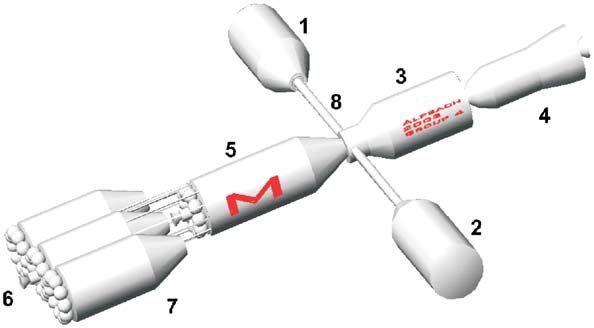
imization led to the arrangement shown in Fig. 6: 1. telemetry and telecommand as well as for communi-
Habitation and Return Module (ERV), 2. Mars Sci- cation and navigation with the Landing Unit and with
ence Laboratory (MSL), 3. Mars Science Observatory relay satellites.
(MSO), 4. Surface Excursion Module (SEM), 5. NTP Depending on the development of laser technology,
second stage, 6. NTP first stage, 7. additional external a high data rate laser link as tested by ESA’s Artemis
tanks and 8. inflatable beam structures. satellite might also be considered for this mission.94 M. Taraba et al. / Acta Astronautica 58 (2006) 88 – 104
3.6. Thermal dissipation Table 3
Technical specifications of the ANERVA
Due to the use of a Bimodal Nuclear Thermal Propul- Thrust (kN) 800
sion (NTP) unit for propulsion and power supply, an Isp (s) 1000
Active Thermal Control System (ATCS) with heat Exhaust velocity (m/s) 9810
pumps [8] and radiators will be needed. Considering Lifetime high/low P. mode 500 min/25 yr
Mass propulsion (t) 6
100% of the in-station power to be dissipated in heat Mass power generator (t) 10
for a first estimation, this total thermal power adds up Power (thermal) (MW) 4000
to about 250 kW. Power (electrical) (W) 3
A two phase loop ATCS to transmit the accumu-
lated heat will be about 2500 kg of mass. An advanced,
lightweight heat rejection material of about 350 W/m2
with a total radiator surface area of 700 m2 will 6 7
be attached to the station and tank surface areas.
At 3.5 kg/m2 the radiator mass will be around 2500 kg, 8
leaving a total Thermal Control System (TCS) mass of 4
about 6000 kg including margins.
1
3.7. Propulsion and power system
3.7.1. Main stages
For the S/C’s propulsion and power system a bimodal
NTP system [9,10] design with liquid hydrogen (LH2 ) 5
as propellant was chosen. Only a NTP system provides 2
sufficient energy per kg of propellant to enable this mis-
sion in a short as possible time frame. Neither solar sails
nor electrical propulsion are capable to fit the given re-
quirements. Fluid and solid rocket engines have far too
much mass and were therefore not taken into account.
For the whole mission three Advanced Nuclear Engine 3
for Rocket Vehicle Applications (ANERVA) are used in
a three-stage design. The advantage of three equal en-
gines is the cheaper development and production costs. Fig. 7. Schematic of the ANERVA Propulsion Module: 1. nuclear
For having constant pressure in the H2 tank there is a core, 2. throat, 3. nozzle, 4. He tanks, 5. thermal shielding, 6. flange
for the H2 tank, 7. He tubes and control valves and 8. nuclear power
control system with He tanks to produce the needed control.
pressure and to control the propellant flow rate.
The described ANERVA system is a bimodal de-
sign with an integrated closed fluid system for driving arrives at Mars, in order to reach the final LMO. Be-
a high-power electrical generator. Some data for the fore this ignition the ANERVA is running in low power
planned ANERVA is listed in Table 3, while Fig. 7 mode to produce electrical energy during the Earth–
shows a schematic of the rocket engine. Mars transfer. After deceleration the ANERVA is run-
The first stage is used for the TMI operation which ning in low-power mode again as main electrical power
accelerates the S/C in order to escape the LEO and generator for the orbital station. The empty LH2 tank
reach the Hohmann transfer trajectory. After this ma- will be used as propellant storage facility and for addi-
noeuvre, it will be jettisoned to dispose the needless tional manoeuvres.
mass of the first stage, the ANERVA, the empty H2 The return stage is for the Trans Earth Injection (TEI)
tanks and the cooling facilities for the propellant. The operation and for power generation on the Mars–Earth
second stage will produce a deceleration when the S/C transfer. The return stage will be jettisoned before theM. Taraba et al. / Acta Astronautica 58 (2006) 88 – 104 95
Aerobrake Maneuver Table 4
& Stage 1 (trans Mars injection)
Rendevous with
Reusable Space Dry mass (t) 511
Plane in LEO 600 Propellant mass (t) 223
Propellant margin 10% (t) 22.3
Total wet mass (t) 756.3
V (m/s) 3571
LH2 mass flow M/t (kg/s) 81.55
Burn time (min) 45.51
ERC Acceleration (g) 0.16
TEI
Mars Earth
Moon
Table 5
NTP + HAB Stage 2 (low Mars orbit injection)
Fig. 8. Aerobrake manoeuvre and rendezvous with a reusable space Dry mass (t) 374
plane in LEO. Propellant mass (t) 88.6
Propellant margin 10% (t) 8.86
Total wet mass (t) 471.5
return capsule enters the Earth’s atmosphere, because V (m/s) 2087
the risk of a nuclear generator flying directly towards LH2 mass flow M/t (kg/s) 81.55
Burn time (min) 18.11
Earth would be too high. After the aerobrake manoeu- Acceleration (g) 0.22
vre, the Earth Return Capsule (ERC) will rendezvous
with a reusable space plane in a 600 km LEO bringing
the astronauts safely back to Earth or to a space station. Table 6
The NTP and the HAB will enter a high Earth orbit and Return stage (trans Earth injection)
could be reused for a future mission (Fig. 8).
Dry mass (t) 96.6
The amount of propellant used for performing a ma- Propellant mass (t) 23
noeuvre, which is modifying the orbit is given by Propellant margin 10% (t) 2.3
−V Total wet mass (t) 121.9
Ma = Mb · e Isp ·g , (5) V (m/s) 2087
LH2 mass flow M/t (kg/s) 81.55
and Burn time (min) 4.68
Acceleration (g) 0.84
Mp = Mb − Ma (6)
result in
3.7.2. Attitude and orbit control system
V
Mp = Ma · e Isp ·g
− 1, (7) Once the station is in its initial orbit it will be per-
turbed by forces acting on it. To counteract these per-
where Mp is the mass of the needed propellant, Ma turbations an attitude and orbit control system (AOCS)
the mass after the manoeuvre and Mb the mass be- has to be installed onboard. Four perturbations were
fore the manoeuvre, V is the velocity change, Isp the considered
specific impulse and g the gravitational acceleration of
9.81 m/s2 . (1) third-body perturbation,
Tables 4–6 give the propellant masses calculated for (2) perturbations due to the non-spherical shape of
the whole M3 mission as well as the ignition times and Mars,
the resulting accelerations. (3) perturbations from solar radiation and,
For cooling of the liquid H2 propellant a special su- (4) perturbations from atmospheric drag.
perinsolation of the tanks is needed and also an active
cooling facility which needs 524 W of electrical power Preliminary investigations have shown that
for each ton of H2 . unlike the station needs to be stabilized very precisely96 M. Taraba et al. / Acta Astronautica 58 (2006) 88 – 104
Solar maximum 3.8. Life-support system
800
H2 The environmentally controlled life-support system
700 O H
(ECLSS) is a combined physico-chemical and biologi-
Altitude [km]
600 cal system. It is based on the assumptions that physico-
N2 chemical systems with a reliably high efficiency have
500
CO
been developed by the start of the mission and that ap-
400 propriate plant species for space agriculture have been
CO2 selected. As M3 is a long-term mission, recycling of
300 O2 consumables is essential.
200 Each of the three pressurized station modules has
102 103 104 105 106 107 108 a physico-chemical system to recycle water, air and
Number density [cm]-3 waste as shown in Fig. 10. The triplicate installation
of the system will provide the necessary redundancy
Fig. 9. Partial pressures in Martian atmosphere at solar maximum.
of the ECLSS. Waste water passes a pre-treatment, re-
verse osmosis and multifiltration to retain clean water.
Urine has to be treated to remove ammonium, which
(e.g. for astronomical science) the first three kinds of is done by Vapour-Phase Catalytic Ammonia Removal
perturbation can be neglected for fuel consumption cal- (VAPCAR), before entering the water recycling pro-
culations and only the constant loss of height due to the cess. Air revitalization is done in three steps, namely
atmospheric drag has to be computed using the follow- CO2 concentration using Solid Amine Water Desorp-
ing equation: tion, CO2 reduction using the Sabatier process and O2
generation using Static Feed Water Electrolysis. The
FD = 1
2 · (h) · CD · MLO (h)2 · Af , (8) atmosphere management also includes N2 generation
(thermal catalytic dissociation of hydrazine), trace con-
where FD are drag forces, (h) is the height-dependent taminant control, temperature and humidity control,
atmospheric density, CD the drag coefficient, MLO the cabin ventilation as well as fire detection and suppres-
velocity of the orbit station and Af the station cross- sion. The biological system consisting of higher plants
section in flight direction. will add to the recycling of CO2 and waste water. Solid
The density was calculated according to latest waste treatment is performed by Super Critical Wet Ox-
density-height figures of the Martian atmosphere for idation (SCWO). CO2 and water resulting from com-
the worst-case scenario of solar max activity (see bustion re-enter the recycling loop, while remaining
Fig. 9, H. Lammer, 2003, private communication). The ashes are discarded.
calculation showed that the drag is in the magnitude of The biological system is set up to supply 40% of
0.01 N. The respective loss of orbit height was in the the food requirements for the crew during the flight to
magnitude of tenth of meters per day due to the thin Mars and the operation time in orbit. For this purpose
Martian atmosphere in this height (0.227 m/day was a planting area of 60 m2 is needed. The other 60% of
calculated). Considering a 25 years design lifetime of necessary food, as well as a redundancy supply for 4
the station the diversion from the initial orbit height months and the food for the return flight to Earth (258
will be 2071 m at maximum. days) will comprise of dry and/or frozen food in storage
Taking all this into account, the orbit chosen ful- compartments. The redundancy supply of 4 months was
fils all the considerations and implements no need for chosen for the case of complete breakdown of the plan-
fuel consuming re-boost of the station during the whole tations because of diseases or pathogens. In this case,
lifetime. Therefore, a relatively low thrust and eco- the time of 4 months would be enough to grow a new
nomic AOCS system equipped with reaction wheels generation of plants. Seeds for new plant generations
and electric-thrusters will be sufficient for station- are gained from plantations and a redundancy amount
keeping. Those thrusters could be pulsed MPD or for the case of breakdown is stored. Plants are grown
arc-jet thrusters. in a hydroponic system in the second artificial gravityM. Taraba et al. / Acta Astronautica 58 (2006) 88 – 104 97
Physico - Chemical System
CO2 Concentration CO2 Reduction O2 Generation
Solid Amine Water Desorption Sabatier process Static Feed Water Electrolysis
CO2 O2
Plants
Condensate
Pre - Reverse Volatile
Multifiltration Clean water
Waste water treatment Osmosis removement
Vapor Phase
Urine Catalytic Ammonia
Removal
CO2
Wet Oxidation
Solid waste Super Critical Water Oxidation Water
Ashes
Fig. 10. Combined physico-chemical and biological recycling system for air, water and waste.
module which, unlike the habitation module, always re- primary importance. It is assumed that until the start of
mains at the station. Plantations are divided in several the mission protective nutrition and medication as well
independent and closed subunits, to avoid the spread- as hydrogen enriched plastics as an effective radiation
ing of diseases and plant pathogens, in case one of the shelter will be available. The career doses of radiation
subunits is affected. Selected plants which meet the range between 1.5 and 3.0 Sv for males, 0.9 and 1.7 Sv
nutrient requirements of the astronauts (mainly wheat) for females [11]. Measurements of radiation protection
or are of high psychological value (e.g. strawberries) begin with the selection of crew members of a certain
will be grown in the hydroponic system. Plantations age (45–55 years) and genetic pre-disposition. Further-
will be of alternating age in order to provide a contin- more, radiation resistance of the astronauts is increased
uous supply of fresh food. The plantation units need a by special nutrition enriched in radioprotective chem-
monitoring and control system for nutrient and water icals (antioxidants, e.g. sodium selenite).
supply, CO2 , O2 , temperature, humidity and ethylene. The station is protected against radiation by a
Besides adding to the recycling of water and air, the hydrogen-rich polyethylene (PE) shielding of a density
plants also promote the psychological well-being of of 10 g/cm2 . Due to this shielding, the radiation doses
the crew. They will add fresh food to the astronauts on blood-forming organs (BFO) caused by galactic cos-
menu, the crew will be occupied several hours a day mic radiation (GCR) are 0.19 Sv/yr for solar maximum
working on the plantation and green plants are known and 0.49 Sv/yr for solar minimum. In both cases the val-
to have a beneficial effect on the human psyche. ues lie below the recommended dose of 0.5 Sv/yr [11].
During solar particle events (SPE) the radiation dose on
3.9. Radiation the orbiting station can be expected to be decreased to
0.39 Sv due to the shielding and the distance between
Radiation is the major health hazard in human space Sun and Mars of 1.5 AU. Accurate radiation monitor-
flight, hence radiation protection of the crew is of ing, dose control measurements and documentation are98 M. Taraba et al. / Acta Astronautica 58 (2006) 88 – 104
extremely necessary during SPE. The Martian atmo-
sphere shields very well against GCR and SPE. The 2nd FLOOR
GCR dose is 0.12 Sv/yr, the SPE dose 0.32 Sv, both for
BFO at the Martian surface. ECLSS 8 9
The station will have a radiation forecast system to
H2O
predict SPEs and a dosimeter on board. For the com- 10
plete mission to Mars a radiation dose of ∼2.5.3 Sv 2nd FLOOR 7
can be expected. Due to the shielding the possibility of 11
excess cancer will stay below 3%.
12
1st FLOOR
3.10. Human factors
1st FLOOR
The crew selection is one of the most important parts
in a human mission. As the mission is designed for six
ERC 6 6
crew members, the best way to fulfil the objectives is to
select as crewmembers a pilot, a medical doctor, an en- 6
1
gineer, a physicist, a geologist and a biologist . Further 5
2 7 4
skills of the crew members have to cover the fields of
3
software engineering and communication, first-aid and LH2 6
psychology. Crew members are aged between 45 and 6 6
55 years (or older), because with increasing age they
are less affected by radiation. Crew members are also
selected by their genetic pre-disposition for radiation
resistance, which may decrease the risk of radiation NTP
sickness by a factor of 10. For psychological reasons
the crew will be composed of both males and females.
Nationalities of the crew members should represent the
participating continents/countries. Fig. 11. Schematics of the habitation module: 1. WC, 2. shower,
3. storage, 4. kitchen, 5. living room, 6. crew accommodations, 7.
Crew members have to be kept in a good psycholog- tunnel, 8. water tank, 9. medical care, 10. storage, 11. control room
ical and physical state during the mission. The habi- and 12. fitness/workshop.
tat is designed in a way to respect the privacy of the
crew members (individual sleeping quarters) and as-
sure their maximal health security (artificial gravity, lar basis. Saturday afternoons and Sundays will be free
radiation shielding). The living quarters are distributed (except during landing mission on Mars) and facilities
over two floors in the habitation module (Fig. 11). Be- for entertainment, hobbies and contact to friends and
sides the sleeping quarters they include a fitness room, family on Earth are provided.
kitchen and living room, as well as storage compart-
ments, space for control systems and a medical care 3.11. Surface excursion module
unit. The two other modules of the orbiting station, one
-gravity and the second artificial gravity module, pro- The Mars Landing Module (MLM) is a partly reusable
vide space for scientific laboratories. There, longterm Lander element which will be used for the first human
comparative studies on gravity effects may be con- landing on Mars. It comprises a Descent Stage for the
ducted during the flight to Mars and later on, samples landing and ground exploration and a reusable Mars
returned from Mars after the landing manoeuvre may Return Vehicle (MRV) with a high level of maturity.
be studied. The crew will be occupied by physical exer- The MLM can carry two astronauts for a mission du-
cises (2–3 h/days), scientific experiments (6–8 h/days), ration of 15 days.
food production and preparation (2–3 h/days) as well as The MRV will be used as habitat (habitable volume
maintenance and housekeeping (3–5 h/days) on a regu- V = 38.5 m3 ) and launcher for the crew to reach theM. Taraba et al. / Acta Astronautica 58 (2006) 88 – 104 99
orbit of the space station. A modular design helps to Utilization (ISRU) equipped MRV were also consid-
adapt the MRV to different landing sites and mission ered. However, it takes 3–4 years to produce the needed
scenarios. The sample return chamber will be only ac- propellant to return to the orbiting station. That leaves
cessible from the outside to avoid contamination of the the only option to send a unmanned ISRU spacecraft
MRV and the station. prior to the manned mission. In addition to that, the
The Descending Stage will be attached to the MRV landing spot would have to be met very precisely later
and is fully expandable. There are several necessary and on. For reasons of flexibility of the landing sites and
optional parts located in the 260 m3 shelter of this stage. mission duration, the ISRU on the Martian surface is
The necessary parts, e.g. the inflatable heat shield, the not feasible for this mission scenario. As propellant
landing gear, a hydraulic and power unit, etc. are very a combination of LOX/LH2 with a specific impulse
low dependent on the chosen landing spot. The remain- of Isp = 420 s (due to losses in nozzle adaptation and
ing space can be equipped in order to meet certain mis- lower efficiency of a small engine compared to, e.g.
sion goals, e.g. drilling machine, robot arm, rover, un- Space Shuttle Main Engine) is chosen. This leads to a
manned glider with balloon, etc. specific exhaust velocity of ce = Isp · g0 = 4120 m/s.
There is no need for more than a one-staged MRV-
3.11.1. V -calculations concept to go from a low inclination landing site into a
The Vtotal can be divided into 5 segments. V1 is LMO (h = 350 km, i = 15◦ ). This is confirmed by the
needed to go from the surface into LMO and can be empiric formula [12]
calculated using the Vis Viva equation 1.12 · Vtotal,min
nmin = = 1.06,
Mars ce
V1 = = 3.85 km/s. (9)
rMars 1.12 · Vtotal,max
nmax = = 1.30, (13)
For losses during the ascent a factor of 10% for float ce
and 2.5% for aerodynamic resistances is added. This where the factor 1.12 results from numerical calcula-
leads to a V1 of 3.997 km/s. tions.
Depending on the landing site, a change in inclina- In order to be able to reach the polar region with the
tion (0◦ < i < 15◦ ) has to be performed. The V2 is Lander in follow-up missions, there should be
calculated by using the Law of Cosines the possibility to include a second ascending stage
between the MRV and the Descending module to reach
V2 = VStation
2
+ VMRV
2
a higher V .
− 2 · VStation · VMRV · cos(i), (10)
3.11.2. Descending to the Mars surface
0.0 km/sV2 0.89 km/s. (11) The first part of the descent is acquired with the use
Furthermore a V3 = 0.025 km/s for the docking ma- of the tether attached to the MLM. Whereas with a
noeuvre and a reserve of V4 = 0.1 km/s have to be static separation, the new perihelion can only be low-
taken into account. The rotation with a period T of 24 h ered by a factor of seven times the length of the tether, a
37 22 reduces the needed V according to the fol- higher braking V can be reached by using a dynamic
lowing formula: separation according to the following formula [13]:
√
cos(i) r0 − rp2 ∼ 7 + 4 · 3 · sin( max ) · L2 . (14)
V5 = 2 · . (12)
T Here r0 is the orbit radius of the space station, rp2 is the
The values for V5 ranges from 0.241 km/s for a land- new perigee radius, max the angel in the orbit plane.
ing site latitude of 0◦ to 0.233 km/s at a landing site L2 is the length of the tether measured from r0 to the
latitude of 15◦ . The sum for the Vtotal therefore ranges expelled MLM. In order to reach the entry corridor,
from 3.881 to 4.779 km/s. optimizations will have to be done.
As a propulsion system chemical propellants with a During the entry, the Lander will be protected by
high-specific impulse were chosen. In Situ Resource an inflatable heat shield, which is stored in the bottom100 M. Taraba et al. / Acta Astronautica 58 (2006) 88 – 104
∆V Braking, MainEngine= 1,0 km/s
Table 7
Height
[km] Mass MRV acc. to mission needs
Lowering A Parachute = 4120 m2
Orbit
Using Ltether ~ 4 km
kg
Tether
~80 Heat Shield EPS 720
jettisoned
Command and Control 140
1st Engine firing
Navigation 30
double dip
Aerobreak
Subsonic Communication 40
Parachute
entry ECLSS 350
2nd Engine firing TCS 70
t [sec] 1800
Mechanisms 130
Robotics 40
Fig. 12. Landing on Martian surface. Structure 1600
Other 50
Payload (EVA, etc.) 300
Tank (structure) 450
part of the Descending Stage and jettisoned after the Engine 1500
first stage of the entry. The main engine will then be Parachute (subsonic) 500
used to decelerate from supersonic to subsonic speed. Tether deployment 20
Then a parachute is opened on top of the MRV to as- Margin 20% 650
sist braking. After the parachute is jettisoned, the main Total dry mass 6590
engine is fired again for the landing, as is illustrated Consumables (2 Pers. Crew, 15 days) 360
in Fig. 12. For a precise landing the Mars Navigation Fuel 15 000
network is used. The Descending Stage remains on the
Total wet mass 21 950
Martian surface while the Ascending Stage returns to
the orbital station. Some maintenance has to be car-
ried out, before the MRV can be launched again, i.e.
the second Descending Stage has to be mounted using Table 8
the robot arm, fuel to be refilled, consumables to be Mass of attached descending vehicle
replaced, etc. (kg)
Tables 7–9 give a survey of the Mass of the MLM.
The mass as well as the costs, Table 10, were derived by Heat shield (inflatable) 4000
Structure and landing gear 1000
comparing the mission scenario to the Apollo [14] pro- Hydraulic 500
gram, the STS [14], the NASA Ref. Mission [15] and Power 400
an Astrium mission study [16]. The total initial mass of EVA equipment, tools 400
the MLM will be Mt = 37 955 kg (Fuel 15 000 kg). The Vehicle 2000
mass to be replaced prior to the next flight to the surface Drilling equipment 5000
Margin 20% 2660
will be 29 635–32 635 kg, depending on the amount of
fuel taken to the surface in order to reach a certain land- Total mass descending vehicle 15 960
ing spot.
3.12. Budgets
Table 9
3.12.1. Mass budget Total mass of two landing scenarios
In a first mission scenario an overall station mass in (kg)
Mars orbit of ∼ 500 t was assumed, which defined an MRV 6590
upper limit for the station design. 2 × Consumables (crew of 2 persons, 15 days) 720
Table 11 shows a preliminary outline of the main 2 × Fuel 30 000
M3 components. All modules have been designed to 2 × Descending vehicles 31 920
have a mass of under 150 t to allow a launch with
Total mass of two landing scenarios 69 230
the Energya evolution-type rocket as described above.M. Taraba et al. / Acta Astronautica 58 (2006) 88 – 104 101
Table 10 Table 11
Cost estimate of the mission M3 mass budget
Equipment inventory Marslander cost Metric tons Station modules
(million EUR)
System MSL MSO ERV Lander
Habitats, modules 1000
Life-support system 100 Structure and mechanisms 47 23 22
Power supply 7 ECLSS and consumables 10 5 30
Communication system 50 EPS 1 1 10
Surface vehicle 150 DMS and communication 0.2 0.2 0.9
Hand tools, machine tools 30 TCS 3.5 2 2
Spares 50 GNC/AOCS 2 2 10
Misc. and reserve 50 ERC and TPS 0 0 10 See Lander
1437 EVA 0 0.8 0.9 section
Maintenance 10 28 1
Tests on the ground 910.1 Experimental payload 5 5 1
Dry mass 78.7 62 87.8
Operation Margin (10%) 8.0 6.0 8.8
Crew training and salary 40 Propellant 6 20 23
Science support 100 Propellant margin (10%) 0.6 2 2.3
Science equipment 50
Propellants 0 Total wet mass 93.3 90.0 121.9 69.3
Consumables (food, etc.) 6
Clothes, hygenic materials 10 Sections Mass (t)
206 Total TMI mass 756.3
Earth–Mars cruise 471.5
Total cost 2553.1 Orbital station around Mars 374.5
Total TEI mass 121.9
The rather high structural masses result from the ap-
plied radiation shielding of 10 g/cm2 . The given num- Table 12
bers are rather conservative mass estimations, which M3 power budget
additionally include margins of 10% both on dry mass
Available power 3000 kW
as well as on propellants in order to account for possible Peak power (kW)
uncertainties.
The ERV is the complete transfer vehicle for the Overall losses 1
Backup batteries/fuel cells 50
return trip to Earth including a crew habitat, a NTP
ECLSS and housekeeping 200
unit with propellant and an ERC with heat-shield of Communication 1
about 11 t which will do the aerobrake manoeuvre at RMS/robotics 2
Earth and rendezvous with the space plane to safely GNC/AOCS 1000
return the crew and payload to Earth. Payload 1
Cooling (propellant, system) 500
The presented budget shows the chosen mission de-
Total consumption 1755
sign to be well within the expectations in terms of mass Margin 41.5%
with an overall orbital station mass at Mars of about
374.5 t. The total launch mass from LEO is 756.5 t with
a permanent station part of 245.5 t staying in Martian mission. Table 12 gives a summary of the main power
orbit when the first crew leaves. This permanent part consuming devices. These are the overall station house-
then can be used by follow-up crews and could later keeping, the AOCS system with electric thrusters and
even allow a permanently manned orbital station. the propellant cooling systems. Still with those high
consumptions the overall margin is about 40% which
3.12.2. Power budget can be used in follow-up missions for station enlarge-
The NTP bimodal power unit provides up to 3 MW ment and/or additional high power payload and
electrical power which is enough to supply the whole instrumentation.102 M. Taraba et al. / Acta Astronautica 58 (2006) 88 – 104
Table 13 be necessary to drill deep below the surface in order
M3 cost budget to escape the likely effects of the oxidant diffusion
System Min. cost Max. cost reaction (2–5 m; the regions above 5 m might be well
(million EUR) (million EUR) investigated at the time the mission launches [18]).
Station 31 000 46 000 Deep Drilling (> 5 m) cannot be done by robots so
Mars Lander 2550 2550 far and needs humans on the surface. On Mars there
Launch cost (7 × HLLV) 1050 3500 might be liquid water under a considerable depth be-
Operations and ground 6000 10 000 low the sterile surface. And if there is water it can
infrastructure
also be assumed that there was/is life on Mars.
Total costs (price basis 2003) 40 600 62 050
• Mars seismology: Seismology is a powerful tool for
investigating the subsurface structure of a planet. If
3.12.3. Cost budget we know more about the Martian structure it will
Considering the uncertainties especially in technol- also be possible to find out something about the mag-
ogy development the proposal of a cost estimate for a netic field which is significantly lower than it was on
future mission is very difficult. The data in Table 13 early Mars. Hence, we plan to install seismometers
have been calculated using the mass-cost ratio of the on Mars.
ISS of about 40 000 to 50 000 EUR per kg which gives • Study landforms related to permafrost: There is ev-
a good estimation for an orbital station and then scaling idence of landforms for which the only plausible
the M3 station in terms of overall mass. explanation is that they were formed by water, e.g.
A rather inexpensive possibility of heavy lift launches tear drop-shaped islands in the middle of large val-
between 150 million EUR and 500 million EUR per leys, ancient shorelines, etc. From such evidence, it
launch are assumed, the operations and ground infras- has become clear that Mars even sported a north-
tructure including mission support, astronaut training ern hemisphere ocean that once covered more than
facilities, etc. are thought to be about 15% of the overall a third of the planet to respectable depths. Archaic
mission costs. water-saturated lake and sea bottoms should have re-
tained their water content as the climate got colder
and the ground froze to deeper and deeper levels.
3.13. Scientific research
Micro-organisms can have adapted to the cold, pop-
ulate the main ecological niches and survive under
With the Mars Lander it will be possible to conduct
conditions that seem absolutely unsuitable for life
several scientific investigations and prepare for follow-
in large populations and a high diversity [19]. The
up missions.
likeliest areas of significant permafrost deposits are
• Drilling cores from the soil of Mars: The Viking Lan- the ancient northern ocean bottomlands, deep major
der only took surface samples a few cm below the impact basin bottoms like Hellas and Argyre, and
surface and did not find any organic matter in the canyon bottoms (especially the outflow areas like
Martian soil. Reason for that might be the strong ox- the Ares Valley landing site for the Mars Pathfinder
idation processes working on the surface. The Mar- Lander).
tian surface material is reactive and its evolution
is connected with the short-wavelength UV radia- 3.14. Follow-up missions
tion, which reaches the soil due to a missing ozone
layer. Further, the strong UV radiation exposure of • Ice drilling cores from the polar caps of Mars: The
the Martian surface can mobilize electrons, which polar regions are of great scientific interest because
are detached on the free oxygen and form adsorbed there it may be possible to find out more about Mar-
oxygen ions on the soil. If water evaporates from sub- tian life forms, but also to investigate the climate
surface ice deposits it reacts with the adsorbed oxy- history of Mars. During the first expedition the Mars
gen ions and forms superoxide radicals. This process Lander will launch in an equatorial region because
can explain the reactive nature of the soil and the ab- the change in inclination requires a lower V and
sence of organic compounds [17]. Therefore it may the entry is easier than for the polar regions. ForM. Taraba et al. / Acta Astronautica 58 (2006) 88 – 104 103
follow-up missions a two-staged ascending stage and nent data communication link to Earth is established
a specially equipped descending stage for manned using a set of antennas. A three-staged ANERVA is
exploration of the polar water-ice caps will be at- used for the propulsion and power system, as neither
tached to the MRV in order to meet the higher V solar sails nor electrical propulsion are capable to fit the
requirements. It is more difficult to land there be- M3 requirements. The physico-chemical and biological
cause of low power and low temperatures available life-support system ensures recycling of water and air,
for the landing vehicles. But in a follow-up mission enough stored dried or frozen food and a planting area
pursued by the second crew travelling to the already of 60 m2 . The station is shielded with hydrogen rich
existing orbital station it might be possible to land PE of a density of 10 g/cm2 against radiation. In order
near the polar caps and take ice drilling cores. The to keep the crew in a good psychological and physical
great advantage of ice drilling cores is the possibility state the habitation module is designed to respect pri-
to extract the whole structure of the ice, which is not vacy and assure their health security. Twice a descent
possible with thermal probes [20]. to the Martian surface can be carried out by two astro-
• ISRU for Martian surface base: Outposts in per- nauts each, using the partly reusable MLM. This will
mafrost areas will be especially challenging to build allow to conduct several scientific investigations, such
and maintain. Settlement may be limited to areas of as taking drilling cores from the soil of Mars, study
patchy permafrost, with construction held to frigid landforms related to permafrost and to investigate the
but not ice-saturated soil and rock areas. Excess wa- Martian subsurface structure using seismology.
ter produced by an outpost’s local permafrost tap The orbital station remains in LMO after separation
may then be trucked, or air-lifted, or eventually from the spacecraft awaiting the next crew of astro-
pipelined to other less advantaged settlements and nauts. In a follow-up mission astronauts could land near
outposts. the polar caps of Mars in order to take ice drilling cores
• Exploration of Martian moons: The investigation of or explore the Martian Moons.
the content of the Martian moons may be of impor- After ∼ 1100 days the spacecraft will meet with the
tance for space missions leading towards the asteroid reentry-vehicle in LEO bringing the astronauts safely
belt and further. The moons most probably contain back to Earth.
water which can be exploited for the crew in the or-
biting station. Deimos, the outer moon of Mars, is
the most accessible small body that is geophysically Acknowledgements
anomalous for out-gassing in the inner solar system,
and thus is a probable source for water ice. Wa- This work was supported by the Austrian Space
ter is needed in Martian exploration for propellant, Agency (ASA), the European Space Agency (ESA) and
life support, and as a chemical and physical process the Austrian Bundesministerium für Verkehr, Innova-
media. tion und Technologie.
M. Taraba wants to thank Prof. Anton Zeilinger for
sending him to the Space Summer School Alpbach and
for the support of this publication.
4. Conclusion
K. Zwintz acknowledges the support from the Aus-
A manned mission to Mars in the year 2031 fo- trian Fonds zur Förderung der wissenschaftlichen
cussing on building an orbital station at an altitude of Forschung (FWF), project Stellar Atmospheres and Pul-
∼ 350 km above the Martian surface was described. sating Stars (P14984).
From this vantage point it will be possible to explore
the Red Planet and facilitate further studies of our solar Appendix
system.
After the final assembly of the M3 spacecraft in LEO, List of Abbreviations
six astronauts will start their journey to Mars reaching
the final orbit 258 days later. On board artificial grav- ANERVA Advanced Nuclear Engine for Rocket
ity is provided by rotation of the spacecraft. A perma- Vehicle Applications104 M. Taraba et al. / Acta Astronautica 58 (2006) 88 – 104
AOCS Attitude and Orbit Control System micromissions spacecraft, Acta Astronautica 52 (2003)
501–510.
ATCS Active Thermal Control System
[3] R.C. Hastrup, D.J. Bell, R.J. Cesarone, C.D.Edwards.T.A. Ely,
A/V ascending stage J.R. Guinn, S.N. Rosell, J.M. Srinivasan, S.A. Townes, Mars
BFO blood-forming organs network for enabling low-cost missions, Acta Astronautica 52
D/S descending stage (2003) 227–235.
ECLSS environmentally controlled life-support [4] A.I. Poland, V. Domingo, Advances in Space Research 8 (11)
(1988) 101–107.
system
[5] D. Cadogan, J. Stein, M. Grahne, Inflatable composite habitat
ERC Earth Return Capsule structures for Lunar and Mars Exploration, Acta Astronautica
ERV Earth Return Vehicle 44 (1999) 399–406.
GCR galactic cosmic radiation [6] J.J. Sellers, Understanding Space—An Introduction to
GET ground elapsed time Astronautics, The McGraw-Hill, New York, 2000, pp. 223–256.
[7] H. Sandler, Artificial Gravity, Acta Astronautica 35 (1995)
HAB habitation module
363–372.
HGA High-Gain Antenna [8] Matthias Gottmann, K.R. Sridhar, Lunar base thermal control
ISRU In Situ Resource Utilization systems using heat pumps, Acta Astronautica 39 (1996)
ISS International Space Station 381–394.
LEO Low Earth Orbit [9] T. Hill, C. Noble, J. Martinell, S. Borowsky, Innovative
approaches to development and ground testing of
LH2 liquid hydrogen
advanced bimodal space power and propulsion systems, 36th
LMO Low Mars Orbit AIAA/ASME/SAE/ASEE Joint Propulsion Conference, 2000.
LOX liquid oxygen [10] G.L. Bennet, R.J. Hemler, A. Schock, Status Report on the U.S.
MLM Mars Landing Module Space Nuclear Program, Acta Astronautica 38 (1996) 551–560.
MOI Mars Orbit Injection [11] HUMEX study on the survivability and adaptation of humans
to long-duration exploratory missions, G. Horneck et al.,
MPD magneto-plasma dynamic
ESTEC/Contract No.14056/99/NL/PA.
MRV Mars Return Vehicle [12] E. Messerschmid, S. Fasoulas, Raumfahrtsysteme, Springer,
MSL Mars Science Laboratory Berlin, 2000, p. 62.
MSO Mars Science Observatory [13] E. Messerschmid, S. Fasoulas, Raumfahrtsysteme, Springer,
NTP Nuclear Thermal Propulsion Berlin, 2000, pp. 160–162.
[14] NASA Homepage, http://www.nasa.gov.
PE polyethylene
[15] NASA Mars Exploration Study Team, Human exploration of
S/C spacecraft Mars, The Reference Mission of the NASA, NASA SP-6107
SCWO Super Critical Wet Oxidation draft, NASA Johnson Space Center, Houston (TX), 1992–1994.
SEM Surface Excursion Module [16] Astrium, et al., European Mars Missions Architecture Study,
SOHO Solar and Heliospheric Observatory Final Report to ESA, Toulouse, July 2002.
[17] G. Rontó, A. Bérces, H. Lammer, C.S. Cockell, G.J.
SOI sphere of influence
Molina-Cuberos, M.R. Patel, F. Selsis, Photochemistry and
SPE solar particle events Photobiology 77 (1) (2003) 1–7.
TCS Thermal Control System [18] A. Ellery, C. Kolb, H. Lammer, J. Parnell, H. Edwards, L.
TEI Trans Earth Injection Richter, M. Patel, J. Romstedt, D. Dickensheets, A. Steele, C.
T-HAB Transfer Habitation Module Cockell, Astrobiological instrumentation for Mars—the only
way is down, International Journal of Astrobiology 1 (4) (2003)
TOF time of flight
365–380.
TMI Trans Mars Injection [19] Astrobiology, G. Horneck, C. Baumstark-Khan, The Quest for
VAPCAR Vapour-Phase Catalytic Ammonia the Conditions of Life, Springer, Berlin, 2002.
Removal [20] E.J. Gaidos, F. Nimmo, Interactions of intrusive volcanism
with permafrost on Mars, 2000, The Second International
Conference on Mars Polar Science and Exploration, Reykjavik,
References Iceland.
[21] T.W. Hall, Artificial Gravity and the Architecture of Orbital
[1] M. Marov, G. Walberg, J. Odds, R. Jitz, Meteorological Mars Habitats, Presented at the First International Symposium on
observations with microstations network, Acta Astronautica 40 Space Tourism (ISST), Bremen, 1997.
(1) (1997) 21–33.
[2] W. Deininger, K.W. Epstein, J.S. Eterno, L. Andreozzi,
S. Sieger, K. Leschly, Low cost access to Mars–MarsYou can also read