Quality Control Methodology for Simulation Models of Computer Network Protocols - arXiv
←
→
Page content transcription
If your browser does not render page correctly, please read the page content below
Quality Control Methodology for Simulation Models
                                                        of Computer Network Protocols
                                                                      Vladimı́r Veselý1 and Jan Zavřel1
                                                  Faculty of Information Technology, Brno University of Technology, Czech Republic
                                                                veselyv@fit.vutbr.cz, xzavre10@stud.fit.vutbr.cz
                                                                                       Abstract
arXiv:2109.12854v1 [cs.NI] 27 Sep 2021

                                                  This paper summarizes know-how about modeling and simulation of computer network-
                                               ing protocols we contributed to the OMNeT++ community. We propose a methodology
                                               aiming to set a reliable ground truth for the quality of simulation models of networking
                                               protocols. We demonstrate the application of this methodology on our EIGRP source code
                                               pull-requested to the INET framework.

                                         1    Introduction
                                         The quality of simulation results depends on the accuracy of used models, namely, on how
                                         precisely models reflect the behavior of the real-world system. In computer science, developing
                                         a proper model and subsequent employment of this model in the running simulation is about
                                         finding a balance between complexity and effectiveness. Model implementation should be ac-
                                         companied by reproducible proof to show how verification and validation (V&V) was done.
                                         Thanks to that, other programmers can assess the accuracy of the model and its feasibility in
                                         the frame of different scenarios.
                                             IEEE 1012 [14] standard defines V&V as processes, which determine whether developed
                                         products of a given activity conform to the requirements of that activity and whether the soft-
                                         ware satisfies its intended use and user needs. V&V processes should provide an objective
                                         assessment of software products, namely, demonstrate software correctness, completeness, ac-
                                         curacy, consistency, and testability. IEEE standard, of course, tries to accommodate whatever
                                         type of software engineering effort, while we will apply its core principles in the field of computer
                                         modeling and simulation.
                                             The domain of computer network protocols is our primary research and teaching interest.
                                         We are periodic contributors of simulation models for the OMNeT++ ecosystem. This paper
                                         focuses on our experience with the testing of developed models and their comparison with
                                         referential implementations. Our goal is to define and demonstrate the methodology that is
                                         helping us to produce precise simulation models.
                                             This paper has the following structure. Section 2 elaborates on inputs of the simulation
                                         model development process. Section 3 describes the proposed methodology on how to validate,
                                         verify and test simulation models; moreover, this section discusses certain challenges and intro-
                                         duces useful practices. Section 4 demonstrates methodology on the use-case of EIGRP models
                                         for OMNeT++ and its framework INET. The paper is concluded in Section 5.

                                         2    State of the Art
                                         The following subsections present different ways of formal description of network protocols,
                                         highlight completely different approaches by their authors in their design and unravel general
                                         best practices of the V&V process. We provide a short overview of the most commonly used
                                         referential implementations by the networking community at the end of this section.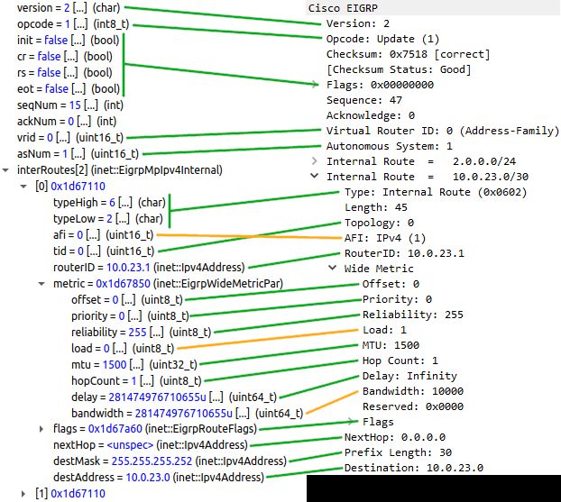
Quality Control Methodology for Simulation Models of Computer Network Protocols           Veselý and Zavřel

2.1      Protocol Definition
Any layered model (e.g., ISO/OSI, TCP/IP, RINA [23]) of computer network slices its function-
ality onto a set of collaborating protocols. Many computer protocols exist to handle different
use-cases due to each protocol’s unique functionality within the fixed scope (i.e., layer). Ba-
sically, all computer networking protocols are defined by the rules of communication, which
specify syntax, semantics, and timing of messages. These rules can be formally described either
using deterministic finite-state machines (FSM) or temporal logic.
    Theory and understanding of FSMs are less comprehensive and more accessible to program-
mers than temporal logic. Therefore, computer network protocol modeling means conversion
of protocol rules onto FSM, where 1) FSM states represent internal communication statuses;
and 2) FSM transitions are a set of actions initiated by messages/events. FSM as a protocol
model is then implemented using means (i.e., languages, built-in tools) available for the selected
domain.
    It depends on the domain if means for behavior/state description and message syntax defi-
nition are different or the same. For instance in OMNeT++, we use C++ (*.cc/*.h files) to
implement behavior, NED language (*.ned files) to layout composition, and message definitions
(*.msg files) for syntax. In the case of network stack within the operating system (OS), most
data-link, network and transport layer protocols (including their messages) are implemented
via C/C++. For message definition purposes, there even exist (semi)automated approaches
that will help with the conversion of protocol specification into source code such as ASN.11 or
Google Protocol Buffer2 .

2.2      Referential Implementations
Standards – such as RFCs, or IEEE 802 series – outline all mandatory protocol rules so that
different implementations are compatible with each other. Nevertheless, some standards allow
or even encourage the flexibility of implementation. For instance:

    • IPv6 is using Extension Headers to add functionality that is not present in the Fixed
      Header. New Extension Headers handling unique use-cases can be created based on
      predefined rules and recommendations [8] (section 4, pages 7 – 25). Even the structure
      of already defined Extension Headers can be the subject of discussion, where different
      parties would implement it according to their needs (e.g., [18]).
    • Similarly to that IS-IS, EIGRP [22] (section 6.6, pages 51 – 52), TCP [17] (section 3.1,
      pages 17 – 19), and others are often using the concept of type-length-value (TLV) fields
      to support easy updates of protocol functionality without the need to standardize a new
      version as is the case with OSPF for example.

    The examples provided above show that the standard itself is not the ultimate source of
protocol definition because actual implementations can also contribute to overall protocol func-
tionality. Therefore, the V&V process should include the comparison of the simulation model
with another implementation of the selected protocol. Choosing the referential implementation
has a significant impact because messages and results generated by this reference affect the de-
velopment process of the simulation model. It would be wise to compare the simulation model
with multiple referential implementations in order to obtain an objective and comprehensive

    1 ASN.1 is codified in the standard available at https://www.itu.int/rec/T-REC-X.680-201508-I/en
    2 Interfacedescription language including code generator is available in the following GitHub repository
https://github.com/protocolbuffers/protobuf

2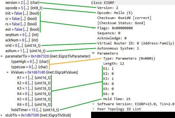
Quality Control Methodology for Simulation Models of Computer Network Protocols   Veselý and Zavřel

evaluation. However, this may be in contradiction with the availability of resources (e.g., time,
hardware) to the programmer. So if just a single referential implementation is used, let it be
the one closest to the simulated phenomenon.
    In our opinion, the best practice for referential implementation is to use an active net-
work device (like a router or a switch) from a well-known vendor. In that case, we have a
chance to test multiple referential implementations on the same device thanks to generally
available firmware updates. Moreover, employers of well-known vendors often co-create (or at
least actively participate in discussions) during the standard development, which makes vendor
implementations more trustworthy regarding compliance.
    Here is a short non-exclusive list of referential implementations we have seen being used
with respect to INET contributions:

   • Cisco Packet Tracer [7]: It is a tool associated with the Cisco NetAcad; it is used as
     a learning environment supporting the teaching of the curriculum of various computer
     networking classes. Diving deeper into details, Cisco Packet Tracer is a discrete event
     simulator containing models mimicking the behavior of selected products (mostly small
     office/home office routers, switches, access points, and security appliances) from the Cisco
     portfolio. Simulation models features have significant differences between different Cisco
     Packet Tracer versions. Based on version changelogs [6], community observations, and
     our insight, Cisco Packer Tracer embeds only limited equipment features. The majority
     of supported protocols are simplified or altered in behavior or message structure.
   • Physical device: If possible, then the physical device with operating systems tailored
     for computer networking is the best referential implementation one can have. However,
     specific protocols might be purposely constrained or not available to align with the busi-
     ness missions of such devices. On the one hand, open standard TRILL protocol is often
     omitted at the expense of similar yet proprietary protocols (e.g., FabricPath). On the
     other hand, originally proprietary protocol EIGRP was released to the public domain,
     but other vendors simply ignore it. Another cavity of employing physical devices is the
     cost because it may be expensive to build analogous topology to the simulated scenario.
   • GNS3 [13], EVE-ng [19]: GNS3 and EVE-ng are emulators of active network devices.
     They can unpack and run binary firmware images (e.g., Cisco IOS files, QEMU images)
     of these devices in virtualized environments. This means that protocol implementation
     on the virtualized device is the same as on the real one. GNS3 and EVE-ng employ
     the same virtualization (either QEMU [4] or Dynamips [10]), but they differ only in the
     end-user interface; while GNS3 requires a dedicated application installed, EVE-ng wraps
     its functionality in the form of a web application. Using both GNS3 or EVE-ng, the
     programmer may easily create complex topologies running tens even hundreds of nodes
     (the only limitation is available CPU and memory on the hosting computer) running
     reliable physical device implementation for nearly zero cost.

    We consider Cisco Packet Tracer as an inferior choice for referential implementation due
to its limitations. The physical device is always the best option when it comes to accuracy to
real-life protocol behavior. However, it is bold to expect that other programmers who want
to repeat the V&V process would possess exactly the same number of devices with the same
peripheral configurations and firmware versions. We prefer to use the emulators mentioned
above because their implementation is identical to physical devices. Moreover, V&V process
reproduction is more effortless because both these tools offer convenient exports of topologies
(including their running configuration and other state properties), which can be easily attached
or referenced in the repositories of simulation models.

                                                                                                   3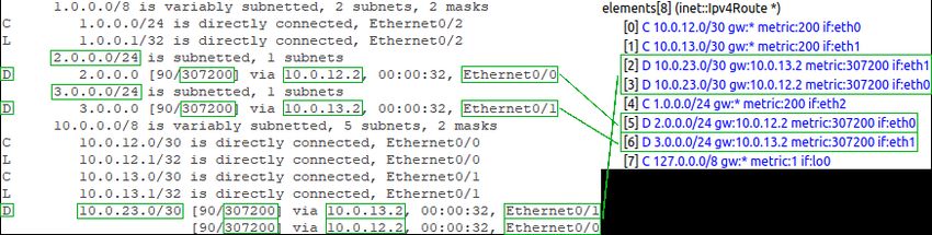
Quality Control Methodology for Simulation Models of Computer Network Protocols    Veselý and Zavřel

3       Quality Control
This paper aims to define a structured V&V process that any programmer may use as a cook-
book for quality control of simulation models. This section briefly informs about various chal-
lenges which may be encountered during the development and testing phases. Then it describes
each step of methodology based on all previously mentioned observations in this article.

3.1     Challenges
Here goes a curated and non-definitive list of challenges impacting development. We provide
our personal view on dealing with these challenges and welcome any counter-opinions.

3.1.1    Level of Accuracy
A complete conversion of all protocol rules may lead to extremely complicated FSM (with
many states/transitions and complex message variants). The situation gets even more tricky
with protocols that offload signalization or data transfer onto other protocols – e.g., IPsec
ESP/AH cooperating with ISAKMP, RTCP/RTP cooperating with H.323/SIP.
    There are approaches and complete tools capable of FSM minimization that would remove
unnecessary states or transitions. However, this type of optimization was most probably already
done by authors during the protocol design. The only other option for reducing complex FSM
is to purposely omit a subset of protocol features. This means a decrease in the accuracy of
the simulation model. There is no rule of thumb for what to include and exclude because it
depends on the programmer’s goals. Nevertheless, the following section might be helpful when
questioning the desired level of accuracy of implemented computer network protocol.

3.1.2    Application of Cryptography
Cryptography is being used in the protocol design to guarantee confidentiality (no one ex-
cept sender and receiver can understand the message), integrity (any tempering with the mes-
sage is recognized by the receiver), and authenticity (identity of single or both parties of the
communication are guaranteed). The programmer needs to decide whether or not to include
cryptography in the simulation model.
     There are two main arguments for why to do it: 1) the messages generated by the simulator
would be the same as messages produced by referential simulation; thus 2) it is the only way how
to also support hardware in the loop (HIL) simulation. The following list represents counter-
arguments why not add cryptography: 1) there is no reason why to support cryptography
primitives in deterministic simulation scenarios – it is a known fact before running the simulation
whether confidentiality/integrity/authenticity is guaranteed or not between involved parties;
2) the boilerplate of the simulation model source code tends to increase dramatically by adding
external libraries handling cryptography (such as OpenSSL [11]); which leads to 3) cryptography
poses an overhead on resources (mainly CPU time and memory) when running the simulation,
which means we need to wait longer for results or we could be even unable to simulate complex
topologies with cryptography enabled.
     Since we have never considered HIL simulations as the use-case for our models, we skip real-
life implementation of the cryptography primitives. To achieve a comparable message structure,
we replace relevant fields within the protocol message with an appropriate magic string. The
magic string can be used as piggybacking mechanism for the receiver that the message “is
encrypted/authenticated” or “with intact integrity”.

4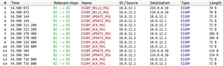
Quality Control Methodology for Simulation Models of Computer Network Protocols    Veselý and Zavřel

3.1.3   Timing

Time is of the essence when comparing protocol messages’ confluence between devices running
referential implementation and simulation models. Referential implementation of the protocol
runs in real-time, while the simulation is governed by a discrete event scheduler (for OMNeT++
see [21], sections 4, 17 and 18).
    Due to the lack of global clocks, it is hard to measure durations, trigger actions, and con-
trol events between devices in real-time. Therefore, it is absolutely mandatory to employ time
synchronization protocols like NTP [20] or PTP [15] for devices running referential implemen-
tation. NTP aims to achieve millisecond-level, while PTP guarantees up to nanosecond-level
synchronization accuracy. Therefore, PTP is always a better choice; unfortunately, most active
network devices support only NTP. If and only if the clocks are synchronized, the programmer
is able to produce reliable baselines in the topologies running referential implementations.
    Every discrete event simulator has built-in mechanisms to schedule events and trigger them
during the simulation run. In the case of the INET framework, ScenarioManager [16] offers
setting up and control over simulation via scripted execution of events defined in the XML file
(see for example Figure 1).
    Scheduling the event in the environment running referential implementation is more com-
plicated (whether the device is real or virtualized). It depends on the vendor, what scripting
options are available. For instance, operating systems of many Cisco devices offer Embedded
Event Manager (EEM) [12] (the configuration snippet disabling specific interface at the given
moment is depicted in Figure 2) or TCL [5]. Instead of preloaded scripts, the programmer may
use a more centralized approach (e.g., Expect [9], Ansible [3]). Scripts are present on a single
machine that would connect remotely (using SSH, Telnet, HTTP) to the device at the right
moment. Scripts would then be executed through a remote connection. In the case of time-
driven scripts, this approach offers more robustness since there is only a single clock controlling
execution and better visibility for the scheduling of event batches.

3.1.4   Control Plane Randomness

The control plane of the actual device runs many different processes, where each is responsible
for a different protocol or functionality. The control plane dynamically switches between these
processes based on OS resource schedulers. This context switching introduces a degree of
randomness, which impacts the reproducibility and baselines’ readability. Following symptoms
relate to this challenge:

   • Stochastic delays are observed in the functionality of referential implementation when the
     control plane is preoccupied with another process;
   • Consecutive protocol messages have non-standard gaps between each other due to the
     packet pacing. This jitter between messages is purposely introduced by the control plane
     either to avoid potential racing conditions between protocol instances or to guarantee
     stable bandwidth consumption.

    Any simulation model cannot accurately abstract above mentioned symptoms. Hence, they
cannot be replicated inside the simulation. This means that any comparison between referen-
tial implementation and its simulated variant should consider the factor of the control plane
randomness.

                                                                                                    5
Quality Control Methodology for Simulation Models of Computer Network Protocols Veselý and Zavřel
3.2 Methodology
At least any V&V process is a natural part of any software engineering effort. We are sure that
every programmer is conducting it in the form of source code testing. In this section, we are
not codifying anything new for the OMNeT++ community. We just want to articulate quality
control methodology related to the development of simulation models, including best practices
based on the previous elaboration of our thoughts.
The proposed methodology consists of six consecutive phases depicted in the following dia-
gram and described below:
○1 Choosing ○
2 Building of ○
6 V&V
○
3 Baselines ○
5 Revisiting the
Referential Testing ○
4 Comparison Reproduction
Production Implementation
Implementation Topology Package
○
1 Choosing Referential Implementation: The initial phase is about choosing the
proper referential implementation compatible with expected simulation goals. As stated
in section 2.2, we recommend either physical devices from a trusted vendor or a network
emulator with a corresponding firmware image.
○
2 Building of Testing Topology: Before employing a developed simulation model in
the large-scale simulation, it is crucial to successfully conduct V&V on the smallest pos-
sible topology, which would offer a good testing ground to assess normal behavior and
treatment of edge cases. It is important to keep parameters (e.g., interface speeds, IP
subnetting, number of adjacent devices, protocol-specific configuration) constant across
real and simulated topology to maintain integrity.
○
3 Baselines Production: We predominantly use the following three types of baselines
produced by referential implementation: a) Syslog messages that include information
about overall control-plane status; b) outputs of show/debug commands that describe in
detail operation of referential implementation; c) PCAP files that contain computer traffic
dumps. While Syslog and show/debug outputs are specific for a single device; PCAP files
offer a view on protocol context between multiple devices since capture contains data from
both directions (i.e., incoming/outgoing to/from selected interface). All above-mentioned
baselines need to include time information which is important for subsequent comparison
with the corresponding simulation scenario. The accuracy for all baseline types can be
potentially enhanced up to nanosecond precision.
○
4 Comparison: Whenever a developed simulation model is ready, it is being tested in
preferably different simulation topologies and various scenarios. All of these test runs
produce results (such as console message, trace, or PCAP) that are inputs for the com-
parison. The rest of this phase is about objective assessment between referential imple-
mentation and simulation model is made. We recognize two levels of such comparison:
protocol level, where we are focusing on the generated messages and their integrity (both
syntactical and semantical); and abstract data structure level, which focuses on states of
abstract data structures used by the protocol, such as the routing table, interface table,
CAM table, topology table for EIGRP, link-state database for OSPF, etc. Needless to
say that a combination of both levels achieves the most objective evaluation. Thanks
to the impact of discussed challenges, differences of various magnitude can be encoun-
tered during the comparison. Hence, it is important to conduct baselines production and
6Quality Control Methodology for Simulation Models of Computer Network Protocols Veselý and Zavřel
comparison repeatedly. There is a very thin line between making the objective compari-
son of ground-truth baseline and simulated behavior, and subjectively choosing matching
simulation results onto the corresponding baseline.
○
5 Revisiting the Implementation: The simulation model can be modified, updated,
or even completely redesigned depending on findings from the previous step. After all
the changes are introduced to the implementation, it is wise to revert back to phases
○4 or ○,5 to verify the validity of changes. This process is repeated until the quality
of the simulation model is sufficient (hopefully, the quality would even exceed original
expectations).
○
6 V&V Reproduction Package: This phase is a memo that result reproduction is es-
sential. Any contributed simulation model should be accompanied by materials (e.g.,
referential implementation version, baselines including PCAP/Syslog dumps, simulation
trace files) that allow reproduction of resulting behavior as proclaimed by the author.
Additional testing and V&V done by the community have a chance to find new errors or
unhandled cases that may further improve the quality of resulting simulation models.
4 Demonstration
This section contains a demonstration of the V&V methodology proposed in Section 3. We
decided to demonstrate this process on INET’s EIGRP simulation model as available in INET
4.3 running in OMNeT++ 6.0 pre10. The simulation model is configured via a combination of
Ipv4NetworkConfigurator for assigning IP addresses and EIGRP specific .xml file which has
a deliberately similar structure to Cisco configuration.
4.1 Choosing Referential Implementation
Currently, the only viable choice for referential implementation of EIGRP is Cisco. Firstly,
Cisco Systems is the author of this protocol. As such, there should be the smallest amount
of discrepancies between the RFC and actual implementation caused by genuine errors and
mistakes in the implementation. Secondly, there are very few other implementations that could
be used as a reference. However, some chapters (e,g. stub routing) are still completely missing
in RFC 7868 [22] even though they are fully operational on Cisco devices. Therefore, we are
using network emulator EVE-ng with IOS version 15.7(3)M2 to build our referential topology.
4.2 Building of Testing Topology
We decided to use the topology shown in Figure 3. It consists of three routers connected to
each other via 10 Mbps Ethernet links. EIGRP is configured on all routers and enabled on
all interfaces. Additionally, each router has its own LAN which is advertised by the EIGRP
process. This demonstration considers two scenarios (with identical configuration).
• Scenario I: Initial Route Discovery: The first scenario focuses on the neighbor discov-
ery, adjacency establishment, and initial routing information exchange process. These are
typical activities when a new router/link is introduced to the topology. In this scenario,
a link between routers R1 and R2 is added. This link is highlighted green in the Figure 3.
When this link is introduced, all routers are already configured for EIGRP and R1 and
R3, as well as R3 and R2, are already neighbors and have exchanged routing information.
7Quality Control Methodology for Simulation Models of Computer Network Protocols Veselý and Zavřel
The addition of this link is the starting event for the measurements. Scenario investigates
traffic between R1 and R2 and R1’s routing table.
• Scenario II: Topology Change Propagation: The second scenario focuses on route
selection and propagation of change in the topology. In this scenario, a link between R1
and R2, previously introduced to the topology in Scenario I, is removed from the topology
after the topology has reached convergence. The disconnected link is highlighted green
in the Figure 3 and the removal of this link is the starting event for the measurements.
This scenario focuses on the traffic between R1 and R3 and R1’s routing table. The result
is expected to be influenced by the race condition as both R1 and R2 will try to advertise
this change in the topology to R3 as soon as possible.
4.3 Baseline Production
Because EVE-ng handles clock synchronization automatically, we just prepared tailored Cisco
EEM applets to execute previously mentioned scenarios on the referential topology. EVE-ng is
capable to dump traffic on selected interfaces into .pcap file that can be analyzed. Wireshark
view for the captured traffic on the referential topology is shown in Figures 4 and 10.
We prepared appropriate XML files for ScenarioManager, which manages intended scenarios
for a simulation. Traffic generated by simulation models can be viewed in the Message/packet
traffic window, and each message can be individually inspected. Some simulation models even
offer export to PCAP, but this is not true for our EIGRP model as of this moment. Captured
traffic in the simulation is shown in Figures 5 and 11.
4.4 Comparison: Protocol Level
For this particular comparison, we focus on messages’ format, content, order and context. While
format can be checked by a simple comparison of messages of the same type, content, order,
and context are harder to compare as it requires a good understanding of the protocol.
The overall packet length can be misleading (at least for this case). There are gen-
uine implementation differences, e.g., the EIGRP simulation model advertises Stub routing
information in every EIGRP Hello message while Cisco includes Software Version and Peer
Topology ID List. Because aspects like messages’ content and order on the referential topol-
ogy can be affected by the control plane randomness, it is generally beneficial to conduct
multiple measurements and closely analyze the one most compatible with the simulation.
4.4.1 Scenario I
Captured traffic between routers R1 and R2 is shown in Figures 4 and 5. This traffic is compared
to each other and most corresponding messages are aligned to the same row in Table 1. A
closer inspection of messages is shown in Figures 6 and 7. The referential topology produces
very consistent results in this scenario with the race condition causing only marginal differences
between measurements. This makes the comparison rather straightforward.
4.4.2 Scenario II
Captured traffic between routers R1 and R3 is shown in Figures 10 and 11. This traffic is
compared and most corresponding messages are put on the same row in Table 2. A closer
inspection of an EIGRP Query is shown in Figures 12. The result on the referential topology
8Quality Control Methodology for Simulation Models of Computer Network Protocols Veselý and Zavřel
is affected by the race condition which caused the disconnected route 10.0.12.0/30 to become
unreachable on router R1 at the very end instead of on the first received EIGRP Reply.
4.4.3 Results
Even though all messages were contextually correct, the simulation model is not perfect in this
regard. The first scenario shows multiple message format errors in TLVs. Another deviation
from the referential implementation the model exhibited is the unnecessary use of unicast during
the initial synchronization. The second scenario shows an error that causes a route with multiple
successors to change into the Active state when one of these successors is lost, which leads to
unnecessary traffic. Overall, traffic patterns are easily recognizable and the simulation models
still exchanged all of the key information needed for correct changes in data structures like
routing or topology table.
4.5 Comparison: Routing Table Level
This comparison focuses on changes to the abstract data structures such as routing table,
EIGRP topology, or neighbor tables which all can be used to assess the behavior of the sim-
ulation model. The snapshot of each of these tables is recorded at the beginning and at the
end of the scenario. After the measurement, we perform simple side-by-side comparison while
concerning namely: route source (identifies how the route was learned, EIGRP labels it with
the letter D); destination (identifies destination network and mask); metric (identifies a value
assigned to reach the destination network); next-hop (identifies the address of next router);
exit-interface (identifies the outgoing interface).
Because the configuration is identical between the referential topology and the simulation,
all of the above-mentioned fields should be the exact same.
4.5.1 Scenario I
Figure 8 depicts the comparison of initial states of the R1’s routing table. Destination
10.0.12.0/30 is not available at this point in either case. After the new link between routers
R1 and R2 is established, it takes only a few seconds for R1 to make necessary changes to the
routing table. Figure 9 shows the state of R1’s routing table after the topology has reached
convergence in both cases.
4.5.2 Scenario II
The initial state for this scenario is the same as the final state from the first scenario (i.e.,
9). The final state of the routing tables for this scenario is shown in Figure 13. All measured
metrics are as expected.
4.5.3 Results
In both scenarios, there was no difference in any EIGRP routing table entry between the
simulation and the referential configuration.
4.6 Revisiting the Implementation
With this new information about the quality of the model, the programmer is able to proceed
with fixing each individual error. While errors like the ones found in Scenario I are easy to fix,
9Quality Control Methodology for Simulation Models of Computer Network Protocols Veselý and Zavřel
as they are mostly just badly predefined numerical values, errors in the FSM like the one found
in Scenario II can be much more complex. It is crucial to repeat the previous step in the V&V
process after the changes are introduced to the model.
4.7 V&V Reproduction Package
All necessary files needed to reproduce our experiments are published on [1]. Results from our
measurements are also included.
5 Conclusion
In this paper, we have mentioned factors impacting the development of simulation models. We
have outlined challenges and provided lessons learned for the V&V process, primarily for the
domain of computer network protocols. The main contribution of this paper is the transpar-
ent methodology that constitutes several phases aiming at improving the overall quality of the
resulting simulation model. We demonstrated this methodology on the use-case of our recent
contribution [2] to INET, which involves full-fledged support of the EIGRP routing protocol.
We hope this paper will stimulate discussion within the OMNeT++ community (and hope-
fully beyond it), which would help find a common agreement on the V&V process for any
contributions.
This work was supported by the Brno University of Technology organization and by internal
research grant FIT-S-20-6293.
10Quality Control Methodology for Simulation Models of Computer Network Protocols Veselý and Zavřel
References
[1] ANSA. EIGRP V&V Result reproduction package. https://github.com/ANSA/results-
reproduction/wiki/OMNeT-Community-Summit-2021, 2021. [Online], Accessed: 2021-07-23.
[2] ANSA. INET EIGRP Pull Request. https://github.com/inet-framework/inet/pull/570, 2021.
[Online], Accessed: 2021-07-23.
[3] Ansible Inc. and Red Hat Inc. Ansible. https://www.ansible.com/. [Online], Accessed: 2021-07-23.
[4] Fabrice Bellard. QEMU. https://www.qemu.org/. [Online], Accessed: 2021-07-23.
[5] Raymond Blair. TcL Scripting for Cisco IOS. Cisco Press, Indianapolis, Ind, 2010.
[6] Cisco Systems. Cisco Packet Tracer 8.x features. https://www.packettracernetwork.com/features.
[Online], Accessed: 2021-07-23.
[7] Cisco Systems. Packet tracer. https://www.netacad.com/courses/packet-tracer. [Online], Ac-
cessed: 2021-07-23.
[8] S. Deering et al. Internet Protocol, Version 6 (IPv6) Specification. RFC 8200, RFC Editor, 2017.
[9] Don Libes. Expect. https://core.tcl-lang.org/expect/index. [Online], Accessed: 2021-07-23.
[10] Christophe Fillot. Dynamips. https://github.com/GNS3/dynamips. [Online], Accessed: 2021-07-
23.
[11] OpenSSL Software Foundation. OpenSSL. https://www.openssl.org/. [Online], Accessed: 2021-
07-23.
[12] Patrick Gargano. Embedded Events Manager. Network Automation, 2020. [Online], Accessed:
2021-07-23.
[13] Jeremy Grossmann et al. GNS3. https://www.gns3.com/. [Online], Accessed: 2021-07-23.
[14] IEEE. IEEE Standard for System, Software, and Hardware Verification and Validation. IEEE
Std 1012-2016 (Revision of IEEE Std 1012-2012/ Incorporates IEEE Std 1012-2016/Cor1-2017),
pages 1–260, 2017.
[15] IEEE. IEEE Standard for a Precision Clock Synchronization Protocol for Networked Measurement
and Control Systems. IEEE Std 1588-2019 (Revision ofIEEE Std 1588-2008), pages 1–499, 2020.
[16] INET. INET Framework DOC- ScenarioManager package. https://doc.omnetpp.org/inet/api-
current/neddoc/inet.common.scenario.ScenarioManager.html. [Online], Accessed: 2021-07-23.
[17] Information Sciences Institute. Transmission Control Protocol. RFC 793, RFC Editor, 1981.
[18] J. Jeong et al. IPv6 Router Advertisement Options for DNS Configuration. RFC 8106, RFC
Editor, 2017.
[19] EVE-NG Ltd. EVE-NG. https://www.eve-ng.net/. [Online], Accessed: 2021-07-23.
[20] D. Mills et al. Network Time Protocol Version 4: Protocol and Algorithms Specification. RFC
5905, RFC Editor, 2010.
[21] OpenSim Ltd. OMNeT++ Simulation Manual. https://doc.omnetpp.org/omnetpp/manual/,
2019. [Online], Accessed: 2021-07-23.
[22] D. Savage et al. Cisco’s Enhanced Interior Gateway Routing Protocol (EIGRP). RFC 7868, RFC
Editor, 2016.
[23] Vladimı́r Veselý, Marcel Marek, and Kamil Jeřábek. Rinasim. EAI/Springer Innovations in
Communication and Computing, 2019(1):139–181, 2019.
11Quality Control Methodology for Simulation Models of Computer Network Protocols Veselý and Zavřel
A Configuration Snippets
Figure 1: The configuration of ScenarioManager for demonstration from Section 4 which dis-
connects and reconnects the link between routers R1 and R2 at 50 and 100 seconds of simulation
time respectively.
R(config)# event manager applet SHUTDOWN-APPLET
R(config-applet)# event timer cron cron-entry "30 15 * * *"
R(config-applet)# action 1.0 cli command "enable"
R(config-applet)# action 2.0 cli command "configure terminal"
R(config-applet)# action 3.0 cli command "interface ethernet 0/0"
R(config-applet)# action 4.0 cli command "shutdown"
R(config-applet)# action 5.0 cli command "end"
R(config-applet)# action 6.0 syslog msg "Applet executed."
Figure 2: Cisco EEM Applet which executes shutdown command on interface ethernet 0/0
at a given time according to the router’s clock, 15:30 in this case.
B Testing topology
Figure 3: EIGRP testing topology. Scenarios are executed by manipulation of link highlighted
in green.
12Quality Control Methodology for Simulation Models of Computer Network Protocols Veselý and Zavřel
C Comparison: Scenario I - Initial Route Discovery
Figure 4: Scenario I - Captured EIGRP traffic between R1 and R2 displayed with Wireshark
Figure 5: Scenario I - Captured EIGRP traffic between R1 and R2 diplayed in OMNeT++
13Quality Control Methodology for Simulation Models of Computer Network Protocols Veselý and Zavřel Figure 6: Scenario I - Comparison of Hello messages between referential topology and OM- NeT++ simulation. Figure 7: Scenario I - Comparison of Update message 13 from referential topology and Update message 11 from the OMNeT++ simulation. 14
Quality Control Methodology for Simulation Models of Computer Network Protocols   Veselý and Zavřel

   Cisco     OMNeT++        Description
    1, 2         1, 2       Exchange of Hello packets. When a router receives a Hello mes-
                            sage from a new neighbor, it creates a new entry for this specific
                            neighbor and sets its status to pending. The content and format
                            of these messages are shown in Figure 6.
   3, 4, 5       3, 4       Exchange of Update packets with INIT flag. These do not con-
                            tain any routing information. On the referential topology router
                            R1 did not acknowledge message 3 in time, so router R2 re-sent the
                            Update as message 4, message 5 contains piggybacked acknowl-
                            edgement for this message.
     6            -         This Update message contains advertised routes from router R2
                            and only appears on the referential topology. This message is
                            sent because the neighbor status from R2’s point of view went
                            from pending to up. This causes the message to be ignored and
                            not acknowledged by router R1 because from its point of view,
                            R2’s neighbor status is still pending as R1 did not receive an ac-
                            knowledgment for its initial update message, message 5, yet.
     7           5, 6       Acknowledgments for initial Update messages. There is only one
                            acknowledgment on the referential topology because it was piggy-
                            backed into the Update message as previously mentioned.
   8, 10         7, 8       Exchange of Update messages containing all advertised routes by
                            both routers. On the referential topology, one Update is sent as
                            unicast because it is a retransmission of message 6. It is also
                            smaller because the router applied the split-horizon rule which
                            prohibits an advertisement of a route towards its next hop. An-
                            other Update on the referential topology is sent as multicast. This
                            is in contrast to the simulation model which uses unicast for the
                            Update messages during the initial synchronization.
   9, 11        9, 10       Acknowledgements for Update messages.
   12, 13       11, 12      Exchange of Update messages advertising networks which have a
                            successor on this interface as unreachable, i.e, 2.0.0.0/24 and
                            10.0.23.0/30 by R1 and 1.0.0.0/24 and 10.0.13.0/30 by R2.
                            This is according to the poison reverse rule. The content and
                            format of these messages is shown in Figure 7.
   14, 15       13, 14      Acknowledgments for Update messages.

             Table 1: Scenario I - Analysis of the traffic between routers R1 and R2.

                                                                                                  15
Quality Control Methodology for Simulation Models of Computer Network Protocols Veselý and Zavřel
Figure 8: Scenario I - Comparison of router R1’s routing table in its initial state.
Figure 9: Scenario I - Comparison of router R1’s routing table after the topology reached
convergence.
16Quality Control Methodology for Simulation Models of Computer Network Protocols Veselý and Zavřel
D Comparison: Scenario II - Topology Change Propagation
Figure 10: Scenario II - Captured EIGRP traffic between R1 and R3 displayed with Wireshark
Figure 11: Scenario II - Captured EIGRP traffic between R1 and R3 diplayed in OMNeT++
17Quality Control Methodology for Simulation Models of Computer Network Protocols Veselý and Zavřel
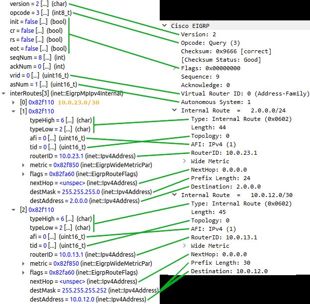
Figure 12: Scenario II - Comparison of Query message 1
Figure 13: Scenario II - Comparison of router R1’s routing table after the topology reached
convergence. Content is identical to the initial state shown in Figure 8.
18Quality Control Methodology for Simulation Models of Computer Network Protocols Veselý and Zavřel
Cisco OMNeT++ Description
1 1 A Query message originating on R1 advertising Active states for
routes 10.0.12.0/30 and 2.0.0.0/24. Query in the simulation also
includes route 10.0.23.0/30 which signifies an error in the DUAL
operation. The content of these Queries is shown in Figure 12.
2 2 Acknowledgements for Query messages.
3 - This Update message, originating on R1, advertises route
10.0.23.0/30 as unreachable. This is according to the poison re-
verse rule and it shows this route being correctly in the Passive state
on the referential topology. Because this route is in the Active state
in the simulation, router R1 has to wait for a Reply which delays
this Update until message 6. Acknowledgment for this Update is
piggybacked in the following Reply.
4 3 A Reply for the previous Query, containing R3’s information about
given routes. This message contains a metric for route 2.0.0.0/24
in both cases. Route 10.0.12.0/30 is also advertised with metric on
the referential topology as router R3 did not yet receive any Queries
from R2. This contrasts with the simulation where router R3 adver-
tises 10.0.12.0/30 as unreachable because it has already received
the Query from router R2. A metric for route 10.0.23.0/30 is also
included in the simulation as it was present in the Query.
5 4 Acknowledgements for Reply messages.
6 5 Update message advertising route 10.0.12.0/30 with metric on the
referential topology and as unreachable in the simulation.
7 6 Update message advertising unreachable routes due to the poison
reverse rule. It contains route 2.0.0.0/24 in both cases, route
10.0.12.0/30 is present only on the referential topology and route
10.0.23.0/30, equivalent to message 3 on the referential topology,
is present only in the simulation.
8, 9 7, 8 Acknowledgements for Update messages.
10 9 Query message advertising route 10.0.12.0/30 in the Active state
for router R3. This message is caused by the arrival of a Query from
router R2.
11 10 Acknowledgements for Query messages.
12 11 Reply advertising 10.0.12.0/30 as unreachable.
13 12 Acknowledgements for Reply messages..
Table 2: Scenario II - Analysis of the traffic between routers R1 and R3
19You can also read