Quick Start Guide 1 Overview 2 Circuit Set-up 3 Prescription Set-up 4 Troubleshooting 5 Warnings - CorVent Medical
←
→
Page content transcription
If your browser does not render page correctly, please read the page content below
RESPOND 19 Ventilator

Quick Start Guide
 1 Overview
 2 Circuit Set-up
 3 Prescription Set-up
 4 Troubleshooting
 5 Warnings

                                              REF 3461-03-9000

RESPOND 19 Quick-Start Guide (EUA), IFU106, Rev. D, DCO#:320, Effective 01/21/2021        Page 1 of 8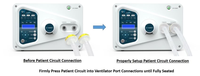
1       Overview
The CorVent RESPOND 19 Ventilator comes out-of-the-box with all the required components
to connect to patients 15mm ETT and begin ventilation.

These components are:
   1.   CorVent RESPOND 19 Ventilator
   2.   RESPOND 19 Patient Circuit (Filters, HME, Flow Sensor, Patient Tubing)
   3.   Flow Sensor Cable
   4.   24V Universal Power Supply
   5.   Operator’s Manual

Refer to Operators Manual for proper patient delivered oxygen prescription setup
*Only use the provided components for patient support. If replacement required, consult the
Operator’s Manual for compatible respiratory circuit components.

RESPOND 19 Quick-Start Guide (EUA), IFU106, Rev. D, DCO#:320, Effective 01/21/2021   Page 2 of 8
CorVent RESPOND 19 Device Features

                        1                              2

                                                                                  Front Panel Device Key
                                                                           1.    User Interface
                                                                           2.    Run/Standby Button
                                                                           3.    Display LCD
                                                                           4.    Flow Sensor Connection
  3
                                                                           5.    Patient and Technical Alarms
                                                                           6.    Exhalation Port
                                                                           7.    From Patient Inlet Port
  4                                                                        8.    To Patient Outlet Port

                             5          6          7       8

                      9          10

                                                                                 Rear Panel Device Key
                                                                                9. Ventilator Enclosure
                                                                     13
         11                                                                     10. Ventilator Air Inlet Port
                                                                                11. Ventilator Label
         12                                                                     12. Oxygen Flow Rate Label
                                                                     14         13. Carrying Handles
                                                                                14. Power On/Off Switch
                                                                                15. Oxygen Inlet connection
                                                                                16. Power Supply
                             15               16

RESPOND 19 Quick-Start Guide (EUA), IFU106, Rev. D, DCO#:320, Effective 01/21/2021                   Page 3 of 8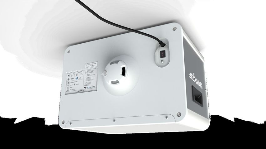
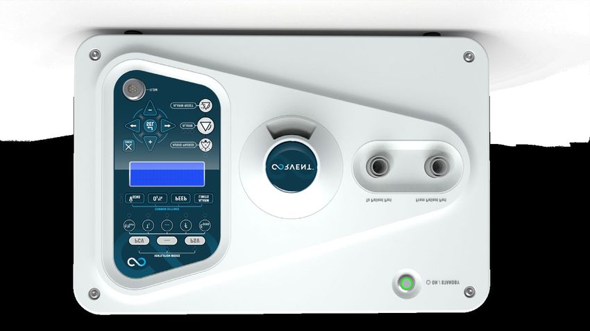
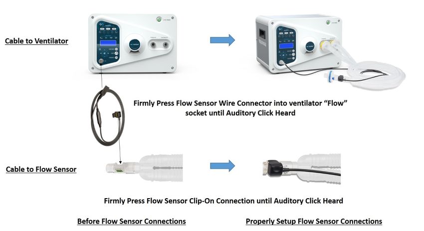
2       Circuit Set-up
                                     Patient Circuit Connection Steps

      1. Connect Proximal Patient Circuit Connections (22mm Yellow Labeled Filters) into
         “To Patient Port” and the “From Patient Port”

      2. Connect Distal Patient Circuit Connection (Blue Label HME) to Patient 15mm ETT

      3. Connect Flow Sensor Cable into Flow Sensor Connection Port

      4. Connect Flow Sensor Cable to Flow Sensor on Patient Circuit

RESPOND 19 Quick-Start Guide (EUA), IFU106, Rev. D, DCO#:320, Effective 01/21/2021   Page 4 of 8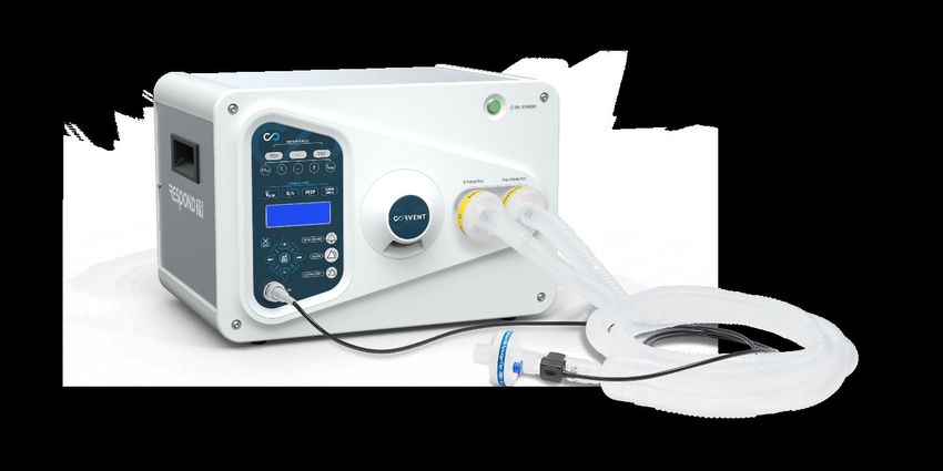
3         Prescription Set-up
Before operating the CorVent RESPOND 19 Ventilator, refer to operator’s manual for
explanation of all breath types, settings, alarms, warnings, definitions and to ensure that the
provided patient circuit is properly configured.
Device Setup
    1. Plug the 24V Universal Power Supply into a UPS that is plugged into the uninterruptible
       backup hospital power system (orange plugs, non-switched).
    2. Flip the Power Switch on the rear of the Ventilator from the O position to I.
    3. The system will automatically default to Invasive Pressure Control Ventilation. In PCV, the
       user is displayed the following settings and monitored parameters. The user may
       manually scroll between screens with the left and right arrow keys at any time.
P   R E S S U R E   C O N T R O L                                            M    V   : X X . X       L   / m i n          B P M : X         X
P   I   X X     P E E P   X X   c m H 2 0                                    V    i   / V e :         X   X X / X X        X   m L           P P
T   I   X . X   s e c                                                         :   X   X   P E E       P   : X . X          M A P : X         . X
B   P M   X X       T S   X X   L / m i n                                    P    F   : X X   L       /   m     I :        E   X : X         . X

 Displayed Settings and Monitored Values in Pressure Control Ventilation. Definitions: PI= Inspiratory Pressure Target, TI = Inspiratory Time, TS =
  Trigger Sensitivity, MV = Minute Ventilation, BPM = Respiratory Rate, Vi/Ve = Inspired/Expired Volume, PP = Peak Pressure, PEEP = Positive End
                        Expiratory Pressure, MAP = Mean Airway Pressure, PF = Peak Flow, I:E = Inspiratory/Expiratory Ratio

    4. Use setting keys to edit desired settings (Green LEDs illuminated to indicate those
       applicable in the current breath type). The settings will update upon user confirmation
       with the Enter (SEL) key or be reverted to previous with Cancel (X) key.
             I.    Each setting when pressed will show a setting page with critical information
           II.     The Up (+) and Down (-) arrow keys can be used to adjust the desired setting
           III.    Each setting is updated upon confirmation (SEL key) and can be changed at anytime

    5. If needed, alarm thresholds can be adjusted from their presets by pressing “Alarm Limits”
       and adjusting Up/Down (High Pressure, Low Inspiratory Pressure, Disconnect Limit, High
       Respiratory Rate Limit, Apnea, High/Low Exhaled Tidal Volume Limit, High/Low PEEP)
    6. Depress Run/Standby Button for two seconds. This button will illuminate green when the
       system is in Run Mode and Ventilating the Patient.
    7. To end Ventilation, depress the Run/Standby button for two seconds. The Request
       Ventilation Stop Alarm will annunciate while the Ventilator will continue to support the
       patient in Run Mode. Press the Alarm Pause key twice in quick succession to confirm
       ventilation shut down. This will place the Ventilator into the Standby Mode.
RESPOND 19 Quick-Start Guide (EUA), IFU106, Rev. D, DCO#:320, Effective 01/21/2021                                                   Page 5 of 8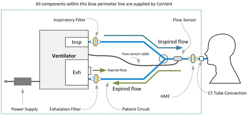
4       Troubleshooting
 If the unit stalls for any reason, push the power button to restart the system.

 Each alarm state will show a screen with possible
 solutions, create an auditory indication, and flash
 the alarm LED with a color corresponding to its
 priority. The Audio Pause and Alarm Reset keys are                          Example: LCD Displayed Alarm Screen for High Pressure Alarm
 provided to temporarily mute or silence the
 audible & visual alarm.

 Refer to Operators manual for complete troubleshooting instructions and alarm details.

 Abbreviated Troubleshooting Table:
        Indication                                  Meaning                                         Corrective Action
   Ventilator does not    Missing or insufficient driving power supply                   Check power source at plug
   operate – no           Patient Circuit Disconnection                                  Reconnect Patient circuit
   patient ventilation    Internal Malfunction                                           Notify CorVent Customer Service
                          Leak in the Patient Circuit or Expiratory Valve                Replace patient circuit
                          Obstruction of gas output
                                                                                         Check or replace patient circuit
   Lower minute
   volume than            Use in hyperbaric condition                                    Ventilator should not be used in
   desired                                                                               hyperbaric conditions
                          Tidal volume control out of calibration                        Notify CorVent Customer Service
                          Internal malfunction                                           Notify CorVent Customer Service
                          Leak in the patient ET-Tube, breathing circuit, or             Check patient interface. Replace patient
                          expiratory valve                                               circuit if at fault
   Tidal volume
                          Ventilator is operating at an altitude different then          Tidal Volume should be measured by an
   inaccurate
                          calibration                                                    external spirometer
                          Tidal volume control out of calibration                        Notify CorVent Customer Service
   Respiratory Rate
                          Respiratory Rate control out of calibration                    Notify CorVent Customer Service
   control inaccurate
                                                                                         Decrease Tidal Volume or Peak pressure
                          Tidal Volume set too high
                                                                                         setting
   Patient pressure too                                                                  ET-Tube may be occluded or patient
                          Patient Response
   high                                                                                  may be biting tube
                          Expiratory valve malfunctioning                                Replace patient circuit
                          Internal Malfunction                                           Notify CorVent Customer Service
                          Expiratory valve malfunctioning                                Replace patient circuit
   Can’t get the
                          Using a circuit not supplied by CorVent                        Replace patient circuit
   desired PEEP
                          Internal malfunction                                           Notify CorVent Customer Service
   Ventilator using too   Leak at Oxygen Source                                          Check hoses and tank regulator for leaks
   much gas               Internal leaks                                                 Notify CorVent Customer Service
                                                                                         Check patient circuit for occlusions,
                          High Inspiratory Pressure Alarm
                                                                                         adjust peak pressure
   Alarm activated                                                                       Check oxygen supply and pressure/tidal
                          Low Inspiratory Pressure Alarm (Disconnect, Apnea)
                                                                                         volume settings. Check for leaks
                          Total Loss of Power Alarm                                      Check power source at plug

RESPOND 19 Quick-Start Guide (EUA), IFU106, Rev. D, DCO#:320, Effective 01/21/2021                                          Page 6 of 8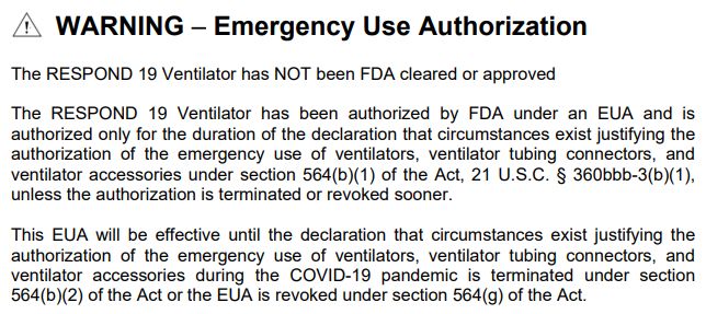
5                   Warnings
Device Usage
The CorVent Respond 19 Ventilator is intended to be used in institutional/hospital applications for invasive and noninvasive mechanical ventilation
support. It requires a robust external monitoring system be in place inclusive of functionality and alarms required for monitoring critically ill and
mechanically ventilated patients.

The RESPOND 19 Ventilator is NOT intended for multiplexing (supporting more than one patient at one time).

DO NOT use the ventilator at an altitude above 3000m or outside a temperature of 10 Deg C to 30 Deg C. Using the ventilator outside of this
temperature range or above this altitude can compromise the ventilator performance which consequently can result in degradation of the health
of the patient. The Ventilator has only been tested at sea level and degradations in performance may occur at higher altitudes.

Loss of Power
Upon loss of power the device will alarm and stop working. The Total Loss of Power alarm will annunciate for greater than two minutes or until
the device is properly powered back on. There is NO internal backup battery. There should be continuous monitoring by qualified personnel and
an alternative means of ventilation is recommended whenever the ventilator is in use. A UPS is required for use to provide up to 30 mins of backup
power upon total loss of mains power supply.

When a UPS is connected, the Ventilator will NOT indicate when the UPS has switched from mains supply to backup battery supply. The user must
rely upon the UPS alarms to understand the status of their mains supply and backup battery life using the audio and visual cues from the UPS.
When the UPS battery is completely depleted, the Ventilator Total Loss of Power alarm will annunciate for >2 minutes.

Patient monitoring
Prior to placing a patient on the ventilator, a clinical assessment should be performed to determine:
       • Needed alternative ventilation equipment
       • Additional external monitors to be used (oximeter (SpO2), blood pressure).
       • Recommended external monitors (Capnography)
CorVent recommends that all patients receive external monitoring and use the recommended external Oxygen monitor to enhance safety and
efficacy of care.

Alternative Ventilation
For ventilator dependent patients, always have alternate ventilation equipment, such as a back-up ventilator, manual resuscitator, or similar
device available. Ventilator dependent patients should be continuously monitored by qualified personnel. These personnel should be prepared to
provide alternate therapy in the event of ventilator failure or inoperative equipment.

Oxygen

When using supplemental oxygen with this system, turn the device on before turning on the oxygen. Turn the oxygen off before turning the device
off. This will prevent oxygen accumulation in the device. Explanation of the Warning: When the device is not in operation and the oxygen flow is
left on, oxygen delivered into the tubing may accumulate within the device’s enclosure. Oxygen accumulated in the device enclosure will create a
risk of fire.

Read Before Using
CorVent RESPOND 19 Ventilator Operator’s Manual

Viral bacteria filter
The device comes with a proprietary patient circuit, HME and viral bacterial filters – only replace with CorVent supplied parts. Operating this device
with incompatible products could lead to fatal or other serious injury due to incompatibility.

The system MUST use both the inhalation and exhalation filters at all times to prevent contamination of the environment and the unit.

Alarm indicators
The high priority and medium priority alarms have the same auditory indication. These two alarm priorities are differentiated by visual indications.
Red signals a high priority alarm and yellow signals a medium priority alarm. Please refer to the operators’ manual for additional alarm information.

Humidification
An HME is provided in the patient circuit to provide for humidification. This may need to be replaced throughout patient support, refer to the User
manual for compatible HME’s.

RESPOND 19 Quick-Start Guide (EUA), IFU106, Rev. D, DCO#:320, Effective 01/21/2021                                                      Page 7 of 8
Information Contact: info@CorVentMedical.com
© 2020 CorVent Medical Inc. All rights reserved.
CorVent Medical Inc. reserves the right to make changes in specifications and/or
to discontinue any product at any time without notice or obligation and will not be
liable for any consequences resulting from the use of this publication.
RESPOND 19 Quick-Start Guide (EUA), IFU106, Rev. D, DCO#:320, Effective 01/21/2021 Page 8 of 8You can also read