RAUPIANO PLUS acoustic drainage - Technical Information. Engineering progress Enhancing lives - Rehau
←
→
Page content transcription
If your browser does not render page correctly, please read the page content below
Engineering progress
Enhancing lives
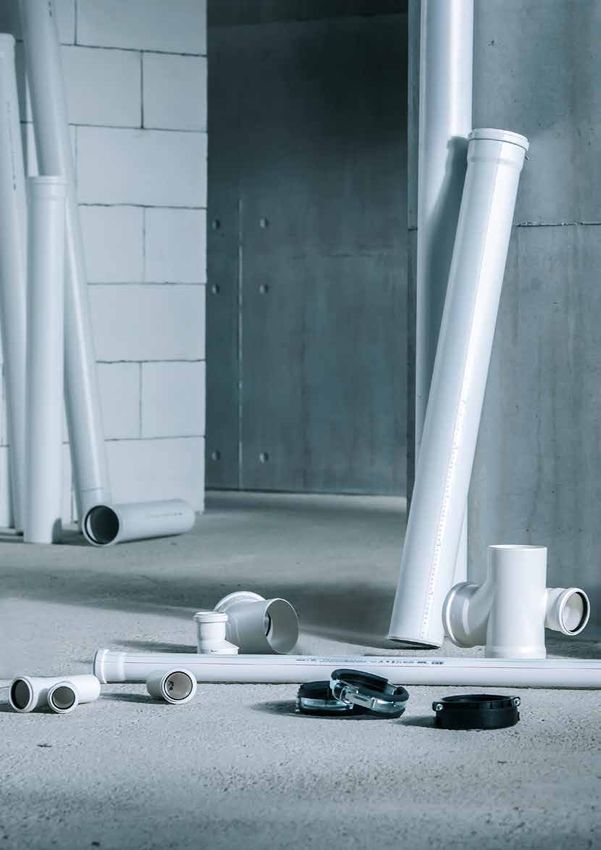
RAUPIANO PLUS
acoustic drainage
Technical Information.
www.myrehau.com
Valid from January 2020
Subject to technical modifications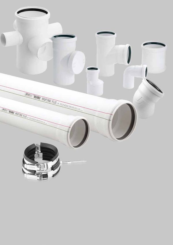
2

Contents
1     Information and safety recommendations    5     8 Installation below ground			        30
                                                      8.1 General            			30
2     System introduction			       6                  8.2 Pipe trench        			30
2.1 Application				6                                  8.3 Embedment          			31
2.1.1 Residential buildings			     6                  8.3.1Bedding materials         		     31
2.1.2 Commercial buildings			      6                  8.3.2Pipe bedding      			            31
2.1.3 Trade waste				7                                8.3.3Filling           			32
2.1.4 Not suitable applications			 7                  8.3.4Compacting        			32
2.2 Pipe Structure				8                               8.4 Connections to pipes and manholes 32
2.3 Fittings				9                                     8.5 Expansion joints in ground 		     32
2.4 Sound insulation 			           9
2.5 Marking				9                                      9 Adaptation to drainage systems		             33
                                                      9.1 Drainage fittings to RAUPIANO PLUS         34
3     Transportation, storage and handling		    10    9.2 Rubber sleeve adaptor for cast iron pipe
                                                          or other materials           		            36
4    Sound Insulation 			                        11
4.1  Basics				11                                     10 Leak test				37
4.2  Sound insulation requirements for Australia 12   10.1 Hydrostatic test 			37
4.3  Sound reduction with RAUPIANO PLUS          13   10.2 Air test         			 37
4.4  Laboratory testing of sound-insulation
     behaviour				14                                  11   Certifications and test reports		         38
4.4.1 Acoustic testing				14
4.4.2 Acoustic test results			14                      12 Technical specifications			39

5   Fire Protection				            16                 13 Chemical resistance			40
5.1 Fire-protection requirements		 16
5.2 Fire collars				16                                14 Standards, regulations and guidelines		     46

6     System Design				               17              15 Appendix A				47
6.1   General drainage requirements		 17
6.2   Equivalent pipe sizes			        17
6.3   Specification				17

7     Installation				19
7.1 Cutting and chamfering			                 19
7.2 Pipe assembly				                         19
7.3 Bracketing				20
7.3.1 Bracketing plan for horizontal pipes		  21
7.3.2 Vertical stack				24
7.3.2.1 Assembly of sound dampening bracket   24
7.3.2.2. Bracketing plan for vertical stack		 25
7.4 Floor waste gully installation		          26
7.5 P-trap siphon / 110mm disconnector gully  26
7.6 Cleaning the waste pipe system		          27
7.7 Socket plug				                           27
7.8 Installing pipes in masonry			            27
7.9 Installing pipes in concrete			           28
7.10 Ceiling penetrations			                  28
7.11 Installation as stormwater piping        28
7.12 RAUPIANO push-fit lock         		        29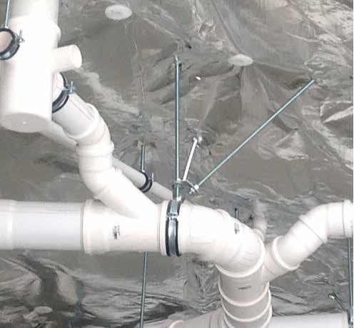
3

This Technical Information RAUPIANO - Acoustic Drainage -
is valid from January 2020.
This publication means that the previous Technical Information
are no longer valid.

The latest version of this Technical Information can be found
at www.rehau.com.au/RAUTITAN or
www.rehau.co.nz/RAUTITAN for download.

This documentation is copyright protected.
The rights of translation, reproduction, drawing of illustrations,
broadcasting, and rendering on photomechanical or by similar
means as well as the storage in data processing systems, are
reserved.

All measurements and weights are of approximate values.
Errors and changes are to be expected.
4

01 Information and safety recommendations

Notes on this technical information                                              General safety measures
                                                                                 - Observe all applicable national and international
Applicability                                                                       regulations on installation, accident prevention and
This technical information is applicable for Australia and New                      safety, together with the information contained in
Zealand.                                                                            this manual.
                                                                        - Keep the work place tidy and free of obstructions.
Navigation                                                              - Ensure there is always sufficient light.
At the beginning of this document, you can find a detailed              - Keep children, house pets and unauthorised persons away
content page which lists the individual chapters and their                from tools and installation area. This is especially important in
respective page numbers.                                                  cases of renovation in occupied areas.

Pictograms and logos                                                    Fire protection
                                                                        Observe the applicable fire-protection regulations very carefully
          Safety information                                            as well as the codes/regulations of building practice that apply in
                                                                        each case, especially in relation to:
		                                                                      - Penetrating through fire compartments.
 Legal information                                                      - Rooms subject to the guideline of places of assembly places.

		                                                                      Personnel requirements
 Important information                                                  - Allow only authorised and trained persons to assemble
                                                                          our systems.
		                                                                      - Work on pipe components should only be performed by
 Information on the Internet                                              persons trained and authorised for this purpose.

		                                                                      Work clothing
 Advantage                                                              - Wear protective glasses, suitable work clothing, safety shoes,
                                                                          a protective helmet and, if you have long hair, a hair net.
                                                                        - Do not wear loose clothing or jewellery. They could be caught
                                                                          by moving parts.
           For safe usage of RAUPIANO PLUS, please ensure you           - Wear a protective helmet when performing assembly work at
           are using the latest version of the technical information.     head level or above your head.
           The date of issue of your technical information is           - Wear NBR gloves when applying lubricant by hand.
always printed at the bottom right of the cover page.
The current technical information is available from your REHAU          When assembling the system
sales office, or as download on the Internet at www.reece.com.          - Always read and comply with the respective operating
au or www.rehau.com.au or www.rehau.co.nz                                 instructions of the tool used.
                                                                        - The cutting tools have a sharp blade. The cutting tools are to
- Read the safety recommendations and operating instructions              be stored and handled in a safe way to prevent injuries.
  carefully and completely for your own safety and for the safety       - When shortening pipes, maintain a safe distance between the
  of other people before starting with the installation.                  hand holding the object and the cutting tool.
- Retain the operating instructions.                                    - Never put your hands near the area where the tool is cutting or
- If you do not understand the safety recommendations or                  on moving parts.
  installation instructions, or if they are unclear, contact your       - When performing service, maintenance and alteration work
  REHAU sales office. Refer to back page for contact details.             and when changing the place of assembly, always unplug the
                                                                          power cable of the tool and secure it against being switched
                                                                          on inadvertently.
Intended use
The system RAUPIANO PLUS may only be installed and operated
as described in this technical information. Any other use is
unintended and therefore impermissible.
5

02 System introduction

ADVANTAGES                                                          2.1.1    Residential buildings

- Excellent sound-insulation properties
- Mineral-filled material for pipes and fitting to reduce
  air-borne noise
- Partially thickened walls for bend fittings to improve
  air-borne insulation
- Special sound-dampening bracket to reduce transmission of
  structure-borne noise
- Fast and easy installation
- The joint is designed to absorb any thermal expansion
- High quality product
- Excellent impact resistance - robust for transport, storage
  and handling at construction site                                 RAUPIANO PLUS is a versatile system for non-pressurized
- UV-resistance, can be stored outdoor for 1 year                   drainage systems which are installed according to AS/NZS
- Smooth yet abrasion-resistance inner layer to reduce risk         3500.2. It is able to comply with the requirements of Building
  of deposits and scaling                                           Code of Australia (BCA) for different types of residential buildings,
- Green material, non-toxic material without halogen                such as:
                                                                    - Double storey homes
                                                                    - Multi-storey apartment blocks
2.1       Application                                               - Condominiums
The sound-insulating drainage system RAUPIANO PLUS is               - Multi storey townhouses
suitable for above & below ground installation inside and outside
the building structure. This is in accordance with AS/NZS 3500.2
and the NCC Volume 3 as certified under Watermark WM70060           2.1.2    Commercial buildings
in buildings and WM71503 below ground. Installation must be
carried out in accordance with AS/NZS 3500.2 and the National
Constructon Code. Observations of DIN EN 12056, DIN EN 752,
DIN 1986-100 and DIN EN 1610 are also recommended.

Behaviour in fire corresponds to B2 normal combustibility
according to DIN 4102 and D-S3,d0 according to EN 13501-1.
The pipe connections are leak-proof up to an internal excess
water pressure of 1 bar (10 m water column). The Push-Fit Lock
socket connection allows for a higher pressure of up to 2 bar (20
m water column). See section 7.14 for more information.

                                                                    RAUPIANO PLUS, with its special acoustic characteristics, can
                                                                    also be installed in commercial buildings that require stricter
                                                                    acoustic requirements such as:
                                                                    - Hotels
                                                                    - Office buildings
                                                                    - Hospitals
                                                                    - Shopping Centres
                                                                    - Supermarkets
                                                                    - Aged Care Facilities

                                                                    RAUPIANO PLUS meets the increasing need for peace and quiet
                                                                    and ensures a high level of living comfort.
6
2.1.3 Trade waste If used in cold areas, where installations are commonly done
under temperature below -10˚C, additional tests are required
according to AS/NZS 7671.
RAUPIANO PLUS has passed the test and therefore marked with
the “ice crystal” according to AS/NZS 7671 and DIN EN 1411 and
can be installed in these regions.
RAUPIANO PLUS is not suitable for siphonic drainage
systems. For outlet of ventilation lines, use pipes
suitable for outdoor installation instead of
RAUPIANO PLUS.
Observe all applicable national and international
The pipes, fittings and seals can be operated continuously at regulations on installation, accident prevention and
90˚C (and up to 95°C for brief periods). They are suitable for the safety, together with the information contained in
drainage of chemically aggressive waste water with a pH value this manual.
of 2 (acidic) to 12 (basic). Please refer to chemical resistance list.
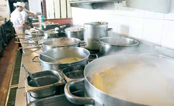
RAUPIANO PLUS is ideal for drainage of greasy waste water
from commercial kitchens up to the grease separator. Areas of application which are not included in this technical
information (special applications) require consultation with our
For lengthy grease waste lines, the use of pipe trace heating may technical department. Please contact your REHAU sales office.
be necessary. This prevents premature grease accumulation.
The temperature of the pipe trace heating suitable for plastic
pipes may not exceed 65°C. Refer to chemical resistance chart in
chapter 13.
2.1.4 Not suitable applications
Pipes and fittings may not be used for:
- installation subjected to continuous operating temperature
higher than 90˚C (or higher than 95˚C for brief periods)
- carrying waste water containing prohibited chemicals
(see section 12 and 13)
- exposed installation to UV radiation (e.g. sunlight) directly
and indirectly
- fuel stations
- oil discharge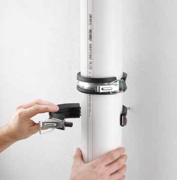
7

2.2       Pipe structure                                                    Features
The RAUPIANO PLUS multi-layer pipe construction achieves                    - Multi-layer pipe system:
superior properties through the application of distinct functional             - Smooth yet abrasion-resistant inner layer made of PP
layers combined                                                                - Rigid middle layer made of PP with
in a composite construction.                                                      sound-dampening minerals
                                                                               - Impact resistance and UV-stabilized outer layer made of PP
                                                                            - Built-in push-fit socket with factory-fitted sealing ring
Three separate layers impart unique characteristics to the pipe.              providing flexible and vibration-resistant joints
The abrasion resistant, low friction inner layer ensures the easy           - Temperature resistance up to 95°C
transit of waste. The mineral filled mid-layer ensures superb               - Chemical resistance from pH 2 – 12. Refer to Chapter 12
sound dampening properties and also offers increased stiffness.               and 13
Finally, the robust outer layer is tough enough to withstand                - High ring stiffness
impacts and shocks.                                                         - 100% recyclable

Together, the composite layers create a tough, durable pipe, with           ADVANTAGES
outstanding acoustic properties that provides all the functionality         - State-of-the-art sound insulation technologies, no acoustic-
of a drainage pipe system combined with the noise absorption                  lagging required
properties of lagging.                                                      - Suitable for special applications requiring high temperature
                                                                              and chemical resistance such as trade waste.
                                                                              Please refer to chemical resistance list.
                                                                            - Green system due to low energy production and
                                                                              100% recyclability
                                      Outer layer:                          - Simple and fast installation
                                      Impact-resistant Polypropylene (PP)   - 100% leak-proof connection
                                                                            - Flexible joint suitable for tremor-prone areas
                                                                            - Fracture resistant at –10˚C.
                   Middle layer:
                   High-stiffness mineral                                   - Uncompromising fire-protection solutions
                   reinforced Polypropylene (PP)                            - Can be stored outdoors for up to 1 year.
                                                                            - Complete pipe, fitting, adapters and bracket range

  Inner layer:
  Abrasion-resistant & low
  friction Polypropylene (PP)

                                                                            RAUPIANO's ideal characteristics are achieved thanks to the
                                                                            three-layer structure of the pipe and the specialised adaptation
                                                                            of each individual layer to its respective requirement:
                                                                            - High ring stiffness
                                                                            - Excellent impact strength of the outer layer at
                                                                                low temperature
                                                                            - Increased UV-resistance
                                                                            - Abrasion-resistant and smooth inner layer
                                                                            - Highly rigid and sound-insulating middle layer made
                                                                                of mineral reinforced PP

Fig. 2-1   RAUPIANO PLUS pipe structure.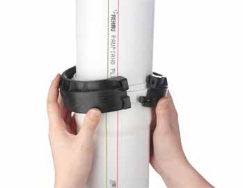
8

2.3      Fittings                                                          2.4       Sound insulation
Redirections in water flow at bends causes increased turbulence            The sound-insulating drainage system RAUPIANO PLUS offers
which results in greater air-borne sound transmission.                     quality, quietness and living comfort in important areas of a
                                                                           building. RAUPIANO PLUS system has been independently
RAUPIANO PLUS bends from size DN110 to DN160 consist of                    tested by Renzo Tonin and Associates, a member of the
targeted mass optimisation zones which help to reduce sound                Association of Australian Acoustical Consultants (AAAC) at
transmission in these areas.                                               the National Acoustic Laboratories (NAL). Test results were
                                                                           assessed by a separate AAAC member to ensure impartiality of
                                                                           the report. The report found conclusively that RAUPIANO PLUS
                                                                           pipe system exceeds the Rw + Ctr 40 requirement of the National
                                                                           Construction Code Vol.1 / Building Code of Australia, and that a
                                                                           stand alone RAUPIANO PLUS system is comparable, in terms of
                                                                           sound insulation, to a fully lagged PVC system behind a specified
                                                                           ceiling separation. Refer to Chapter 3 Sound insulation.

                                                                           The acoustic test letters from the assessing acoustic engineers
                                                                           are available in the Appendix A.

                                                                           2.5      Marking
                                                                           Pipes and fittings are marked with the following:
                                                                           - Watermark
                                                                           - Manufacturer’s mark
                                                                           - Approval number
Fig. 2-2   RAUPIANO PLUS bend with reinforced impact area.                 - Mark of quality
                                                                           - Ice crystal (AS/NZS 7671 and DIN EN 1411)
                                                                           - Nominal diameter (DN)
                                                                           - Year of manufacture
                                                                           - Production line
                                                                           - Material
                                                                           - Distance markers
                                                                           - Angle specification (with elbows and branches)

Fig. 2-3   Specially designed bends with increased wall thickness reduce
           air-transmitted sound even further.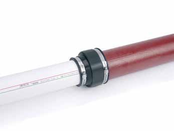
9

03 Transport, storage and handling

Transportation                                                     - Ensure that the wood frames are aligned squarely
RAUPIANO PLUS proves its robustness during transport and             when stacking.
at the construction site thanks to its three-layer structure and   - Store pipes in such a way that no objects are placed on top
impact-resistant and shock-proof outer layer. Ensure that pipes      of or in the sockets and male ends and that these are
make firm contact over their entire length.                          not deformed.

Storage                                                            RAUPIANO delivery procedure
- Protect boxes from moisture during transport and storage.        Key points to remember:
- RAUPIANO PLUS and its seals can be stored outdoors for           - Treat RAUPIANO with care to avoid damage.
  up to 1 year                                                     - Take pipe out of bags prior to delivery to check condition.
                                                                      Put back in bag if possible.
We recommend:                                                      - Do not over tighten the ratchet on the ute.
- Protecting RAUPIANO PLUS pipes and fittings from direct          - Pipe can still be used with small indentations as long as
  sunlight and soiling by:                                            both the male and female ends are not damaged and
        - storing in the box                                          the O-ring is in place.
        - covering them with tarpaulins
            (ensure proper ventilation).
- Stack no more than four wooden crates on top of one another.

Correct transportation procedure                                   What not to do

Where possible use a truck for deliveries.                         Do not throw pipe into the tray     Do not throw pipe off the ute
Lay pipe flat on the tray

Keep pipe strapped down so it doesn’t roll around                  Do not over tighten with ratchet    Take care with O-rings and
and remains supported                                                                                  ensure they are in good
                                                                                                       condition

Alternate socket and pipe ends when loading pipe                   Unsupported pipes can bend          Keep pipes clear of building
                                                                                                       debris whilst on site

Fig. 2-4   Transporting of RAUPIANO PLUS
10
04 Sound insulation
4.1 Basics Air-borne noise
In every area of building construction, especially the construction Air-borne noise is present if the noises of a sound source are
of multi-storey apartment blocks, hospitals and rehabilitation transferred directly through the air to human ears.
homes, sound insulation plays an increasingly important role.
One of the most significant sources of sound within buildings is Structure-borne noise
the sanitation set-up and the accompanying drainage water pipe With structure-borne noise, the sound transfer first occurs
system. through a solid body. This body vibrates and passes the
vibrations on to human ears as airborne noise.
Typical sources of sound include:
- Fitting noises
- Filling noises
- Draining noises
- Inlet noises
- Impact noises
- Turbulance
Unsuitable drainage pipe system and type of brackets are
considerable contributors to disturbing noise. RAUPIANO PLUS,
a system-tested, versatile sound-insulating drainage water
Airborne noise
system addresses these concerns.
Structure-borne noise
A differentiation is made between air-borne noise and structure-
borne noise.
Fig. 4-1 Air-borne and structure-borne noise.11
4.2 Sound insulation requirements for Australia For the Northern Territory:
Sound insulation requirements differ from country to country - Rw 45 if the adjacent room is habitable (other than a kitchen);
and from one building type to another. In Australia the NCC / or
BCA Volume One Part F5 outlines the requirements for sound - Rw 30 if the adjacent room is a kitchen or non-habitable
insulation:
- F5.6 Sound insulation rating of services Weighted sound reduction index (Rw) is the number used to rate
the effectiveness of a system as a noise insulator. An increase in
one Rw unit approximately equals a reduction of one decibel in
NCC/BCA Acoustic requirement noise level.
The NCC / BCA specifies that if a pipe that is located in a wall
or floor cavity, serves or passes through more than one sole- Weighted sound reduction index plus spectrum adaptation term
occupancy unit, the pipe must be separated from the rooms by (Rw+Ctr) takes into account the lower frequency noise. Ctr is a
construction with an Rw+Ctr of: negative number, so Rw+Ctr value will always be lower than Rw
value.
- 40 if the adjacent room is habitable (other than a kitchen); or
- 25 if the adjacent room is a kitchen or non-habitable
Seperation between the noise source
Kitchen Bathroom Bedroom (water/waste) and the habitable room
must have a sound reduction level of
Rw + Ctr 40 according to NCC/BCA
Volume 1 Class F5.6 for services passing
Rw + Ctr 25 through habitable rooms. For the
Northern Territory a sound reduction level
of Rw 45 is required.
Rw + Ctr 40
Kitchen Bathroom Bedroom
Fig. 4-2 NCC/BCA Acoustic requirement.12
4.3 Sound reduction with RAUPIANO PLUS UNPROTECTED PIPEWORK
Both structure-borne and air-borne noises occur in drainage
pipe systems. The wall of the pipe vibrates due to water currents
and flow noises. The type and intensity of these pipe vibrations
depend on a variety of factors, such as the mass of the pipe, the 1 2
pipe material, its inner sound dampening material and installation
method.
3
The pipe vibrations are emitted directly from the pipe as air-
borne noise and are transferred as structure-borne noise via the
pipe brackets to the wall.
When developing a sound-insulating drainage water system, 4
both types of noise distribution must be taken into account.
Fig. 4-4 Sound distribution with sewer pipe systems.
Airborne noise insulation with RAUPIANO PLUS
Airborne noise is reduced by RAUPIANO PLUS due to special
1 Structure-borne noise
materials, sound-dampening minerals and increased weight of
the pipe system. Targeted mass optimisation in sound-sensitive 2 Standard drainage pipe
areas of fitting elbows of nominal diameter DN 110 to DN 160 3 Standard bracket (pipe bracket with/without rubber ply)
provides further improvement at redirection points. 4 Airborne noise
Structure-borne noise insulation with RAUPIANO PLUS
The transmission of structure-borne noise to the wall is
reduced with RAUPIANO PLUS with the use of patented, sound PROTECTED PIPEWORK
dampening brackets:
- A supporting bracket with loose gap in the pipe is fastened
to the wall
- A fastening bracket rests onto the supporting bracket, 2
keeping the pipe in position
1
This extensive physical decoupling of the pipe, bracket and 3
5
wall means that the transmission of structure-borne noise is
eliminated to a high degree (see Chapter 7 for installation details).
4
Fig. 4-5 Sound insulation with RAUPIANO PLUS.
1 Reduction of structure-borne noise
2 RAUPIANO PLUS pipe with sound-dampening fillers
3 RAUPIANO PLUS bracket, patented sound-dampening
support bracket
4 Reduction of airborne noise
5 Reduced overall noise level13
4.4 Laboratory testing of sound-insulation behaviour Our extensive acoustic test results provide the necessary data
for both categories.
4.4.1 Acoustic testing
Acknowledging the different installation practices and the Buildings not regulated by NCC/BCA
effects on acoustic level reading in the building, REHAU engaged The acoustic requirements of buildings outside of NCC/BCA’s
several acoustic consultants to perform extensive acoustic scope tend to be different. The rooms are normally classified
tests on RAUPIANO PLUS drainage system under different differently, and therefore have different noise level requirements.
configurations. The acoustic tests were performed in: The LAmax and the LAeq values are more of important values
than Rw+Ctr.
- National Acoustic Laboratory (NAL) by Renzo Tonin
& Associates RAUPIANO PLUS has gone through extensive acoustic testing
- McLay Industries Facility (MIF) by ASK Consulting Engineers with different ceilings, ranging from flush plasterboard to
- Technical and Further Education South Australia (TAFE SA) Rondo ceiling grid system with lay in tiles, and with different
by AECOM plasterboard thicknesses.
RAUPIANO PLUS pipe system has been independently tested From very extensive raw data collected through
using an established acoustic industry test based on ISO 140 real-life acoustic tests, AECOM assessed the acoustic
testing methodology and independently rated to ISO 717, then performance of RAUPIANO PLUS and it was positively
assessed in accordance with the requirements of NCC/BCA. concluded that RAUPIANO PLUS achieves Rw + Ctr
40 (Rw 46) with 10 mm plasterboard. That means
To ensure close proximity to real-life noise, full-toilet flush was RAUPIANO PLUS satisfies BCA’s acoustic requirements
used during measurement. Full-toilet flush represents the worst- for habitable and non-habitable areas with just 10
case scenario in domestic drainage environment. The water mm plasterboard, without pentrations, lagging and
swirling and turbulence from toilet flush, and therefore the noise insulation batt.
created by them, cannot be replicated by any other noise source
such as continuous water flow. The acoustic assessment letters from the acoustic
consultants (Renzo Tonin & Associates, ASK Consulting
4.4.2 Acoustic test results Engineers, and AECOM) can be found in the website’s
In Australia and New Zealand, buildings can be classified into download section under www.rehau.com.au/raupiano
two categories: and www.rehau.co.nz/raupiano. The complete test
- For buildings regulated by NCC/BCA reports can be provided upon request.
- For buildings not regulated by NCC/BCA
Minimum BCA Minimum BCA
requirement for requirement for
non- habitable areas habitable areas
PVC PIPE Rw + Ctr 28
no lagging*
PVC with lagging +
13mm plasterboard + Rw + Ctr 42
R1.5 insulation batt
RAUPIANO PLUS + Rw + Ctr 42
13mm plasterboard + (Rw 49, Ctr -7)
R1.5 insulation batt
Rw + Ctr 40
RAUPIANO PLUS +
10mm plasterboard (Rw 46, Ctr -6)
Rw + Ctr
0 5 10 15 20 25 30 35 40 45
Acoustic testing
* Boral Selector + Feb 2009 - System WP13, 13mm std core plasterboard with insulation (Graeme E Harding & Associates)14
RAUPIANO PLUS perfromance is confirmed once a
ceiling is in place. Exposed RAUPIANO PLUS installation
can compromised the acoustic performance.
To ensure full compliance to the NCC/BCA acoustic requirements, the following configurations are recommended:
RAUPIANO PLUS Achievements
Rw + Ctr 25 (non-habitable areas) Rw + Ctr 42 (habitable areas)
Rw + Ctr 40 (habitable areas)
Approved fire collar* Approved fire retardant mastic or Approved fire collar*
caulking material*
R1.5, 75mm Glass wool Insulation
10mm standard plasterboard
13mm standard plasterboard
Fig 4-7 Recommended suspended ceiling configurations to comply with NCC/BCA acoustic requirements
* The above schematic shows a general example and is not intended to satisfy the installation requirements for any particular project. Specific fire protection
measures may or may not be required depending on building class and design, check with fire engineer and refer to the National Construction Code for detailed
information.
Buildings not regulated by NCC/BCA - RAUPIANO PLUS produces noise levels within 3 dB(A)
The acoustic requirements of buildings outside of NCC/BCA’s compared to lagged PVC and lagged HDPE when the
scope tend to be different. The rooms are normally classified suspended ceiling is installed without insulation batt. This
differently, and therefore have different noise level requirements. noise difference is not noticeable by human ear.
The LAmax and the LAeq values are more of important values
than Rw+Ctr.
RAUPIANO system shall be decoupled from all
RAUPIANO PLUS has gone through extensive acoustic testing other structures, materials and services to minimize
with different ceilings, ranging from flush plasterboard to sound transmission.
Rondo ceiling grid system with lay in tiles, and with different
plasterboard thicknesses.
- RAUPIANO PLUS produces lower noise levels compared to The acoustic assessment letters from the acoustic
lagged PVC and lagged HDPE when the suspended ceiling is consultants (Renzo Tonin & Associates, ASK
installed with insulation batt Consulting Engineers, and AECOM) can be found in
the website’s download section under
- RAUPIANO PLUS produces lower noise levels compared to www.rehau.com.au/raupiano and
lagged PVC when it is installed in wall cavity (vertical stack www.rehau.co.nz/raupiano. The complete test
pipe), when the wall cavity is installed with insulation batt. reports can be provided upon request.15
05 Fire protection
The behaviour of RAUPIANO PLUS in a fire corresponds - When planning and assembling fireproof collars, the
to material class B2 (normally inflammable) in accordance requirements of the general building construction
with DIN 4102, Part 1. approval and the specifications of the assembly
instructions must be observed.
5.1 Fire-protection requirements - When using fireproof collars, the applicable national
With regard to drainage pipes, fire-protection measurements regulations must be observed.
may be necessary if pipes penetrate through fire-rated building
elements in a building.
Approved fire collar solutions for RAUPIANO PLUS pipe are
available from the following manufacturers:
With regard to fire protection, the applicable national
regulations and the valid codes/regulations of building - Promat (1800 776 628 or www.promat.com.au)
practice are to be observed. - Ramset (1300 780 063 or www.ramset.com.au)
- Snap (1300 76 46 26 or www.snapcollars.com.au)
- Hilti (131 292 or www.hilti.com.au)
5.2 Fire collars - Allproof (+64 9 481 8020 or http://allproof.co.nz)
RAUPIANO PLUS system can be installed with suitable fire
collars which have been tested and proven according to AS IMPORTANT: Not every fire collar is tested and approved
1530.4 to fulfill the fire protection requirements from NCC/BCA. with RAUPIANO PLUS
For fire protection of penetrations through fire-rated ceilings and Contact the manufacturer of the fire collar for information
walls, it is compulsory to install suitable fire collars that will not on fire test results and assembly/installation instructions to
reduce the fire-rating of the particular building elements. determine which solution suits your requirements.
Avoid direct contact between RAUPIANO PLUS pipe and the
building element to avoid transmission of structure-born noise
into the building element. Use fire rated soft caulking material Retro-fit fire collar Cast-in fire collar
to close gaps between the fire collar and the pipe. The caulking
material must be tested and approved by the manufacturer of
the fire collar to be installed together with RAUPIANO PLUS pipe. h1
h2
We recommend to always get an approval from the responsible
construction authority for compliance with the respective
requirements.
Some Fire Collar Manufacturers have approved results with
RAUPIANO Pipe in the fire collar and some have with the pipe Fig. 5-2 Installation of fireproof collar in ceiling*
and socket in the fire collar. Refer to fire collar manufacturers for
this detail.
Wall penetrations require two collars (on both sides
of wall). All floor waste gullies require specific fire
protection collars.
Fig. 5-3 Installation of fireproof collar on wall*
* General example only. Refer to fire collar manufacturer for installation details.16
06 System design
6.1 General Drainage Requirements Approval in Australia and New Zealand
The design and installation of RAUPIANO PLUS drainage system Pipes and fittings are certified under Watermark Certificates
shall comply to AS/NZS 3500.2. WM70060, WM71501 and WM 71502 for sizes DN 40 to DN
200 and also under WM 71503 for sizes DN110 to DN200.
The goal is to ensure intended functioning of the universal System shall have BRANZ approval in New Zealand.
drainage system RAUPIANO PLUS, i.e.
- Back siphoning and leaking of water seal column must System design and performance
be prevented Planning, installation and commissioning are to comply with AS/
- Ventilation of the drainage system must be ensured NZS 3500.2 and RAUPIANO PLUS - THE VERSATILE ACOUSTIC
- Nominal diameter larger than those calculated are not to be DRAINAGE AND TRADE WASTE SYSTEM - INSTALLATION AND
used to ensure effective drainage TECHNICAL MANUAL.
- Sewage must drain with little noise
- Anaerobic digestion is to be prevented System component – Pipes and Fittings
- Gas emissions are to be lead out without harmful effects via Pipe materials shall be composite polypropylene
the main ventilation system RAU-PP, consisting of polypropylene inner layer, mineral-filled
polypropylene middle layer and UV-stabilised polypropylene
6.2 Equivalent pipe sizes outer layer, complying with AS/NZS 7671 for gravity drainage
and stormwater drainage system in residential and commercial
applications.
Pipe sizing chart Fitting materials shall be mineral-filled polypropylene for
acoustic performance enhancement, complying with AS/NZS
PVC RAUPIANO PLUS 7671 for gravity drainage and stormwater drainage system in
DN OD DN OD residential and commercial applications.
(mm) (mm)
Pipes and fittings shall be designed for an operating temperature
40 43 40 40 of 90°C and shall temporarily withstand temperatures of up
50 56 50 50 to 95°C and marked with ice crystal to indicate suitability for
installations under extreme low temperatures up to -10°C. They
65 69 75 75 shall have excellent chemical resistance and withstand acidity
100 110 110 110 level from pH 2 - 12. The packing shall be done to reduce the
effect of UV radiation on the pipe and fitting material and to
150 160 160 160
protect them from dirt and other foreign materials.
Table 6-1 Equivalent pipe sizes.
System component - Sound-dampening bracket
When connecting RAUPIANO PLUS directly to Sound-dampening bracket shall be rubber-lined with vibration-
PVC systems, some dimensions require connection decoupling system to reduce the structure-borne noise
adapters. Refer to chapter 9 for details. transmitted from the RAUPIANO PLUS system.
System component - Floor Waste Gully
6.3 Specification Floor Waste Gully material shall be polypropylene RAU-PP. The
Floor Waste Gully shall have 1 main inlet in dimension DN (OD)
General 110mm with socket and 3 additional inlets in dimension DN (OD)
RAUPIANO PLUS system is suitable for acoustic drainage, 50mm. The outlet shall be of dimension DN (OD) 75mm. Floor
acoustic stormwater and trade waste application. It can be Waste Gully shall have a removable inserted baffle. The total
installed inside the building and below ground. height shall be 222 mm.
Standards Connections
NCC/BCA National Construction Code / Building Code The connections between the polypropylene pipes and fittings
of Australia shall be of leak-proof push-fit socket connection with Styrene
NZBC New Zealand Building Code Butadiene Rubber (SBR) sealing ring. The connections shall
AS/NZS 3500.2 Plumbing and drainage – Sanitary plumbing be able to withstand internal pressure of up to 100 kPa and
and drainage accommodate thermal expansion.
AS/NZS 7671 Plastic piping systems for soil and waste
drainage (low and high temperature)
inside buildings - Polypropylene (PP)
AS/NZS 5065 Polyethylene and polypropylene pipes
and fittings for drainage and sewerage
applications17
07 Installation
All schematics show general examples only and are 7.2 Pipe Assembly
not intended to satisfy the installation requirements
for any particular project. For the installation of
RAUPIANO PLUS waste water piping system, national and local
codes, rules and regulations, as well as local conditions and the
demands of the end use customer need to be considered.
7.1 Cutting and Chamfering
90° 1. Clean dirt from sealing ring, socket interior and pipe end.
2. Use small amount of RAUPIANO lubricant (eg. a 10mm drop)
to moisten male end and O-ring and slide into the socket
until it stops.
3. Mark inserted male end in this position at the socket edge
with a pencil, pen etc.
ca. 10 mm
Fig. 7-1 Pulling out pipe ends for expansion joints.
1. Cut the pipes with common pipe cutters or a To accommodate thermal expansion of RAUPIANO system, the
fine-toothed saw. following conditions are recommended. Ensure witness mark is
2. Make a cut at 90° angle from the pipe axis. visible to ensure that the pipe is not accidentally pulled out.
3. De-burr the inner diameter of the pipe.
4. For connections to push-fit socket pipe systems, taper Insert fully and pull out 10mm per pipe for:
the pipe ends with a tapering tool (i.e. Rothenberger - Pipes longer than 500mm;
Rocut tool for pipes DN40 to Insert spigot end fully into socket for:
DN110 or a coarse file at an angle of approximately 15°). - Pipes shorter than 500mm;
- In ground applications;
- Fitting to fitting.
Fittings shall not be cut. Below ground installation
When the pipe is installed below ground it is not
required to pull the male end out by 10mm to
provide an expansion joint.
Each RAUPIANO PLUS pipe socket can accept the changes
in length of a waste pipe up to 3 m in length (coefficient of
linear expansion in accordance with DIN 53752 averages
0.09 mm/(m·K) at 0°C to 70°C).18
7.3 Bracketing
SD
Sound-dampening bracket
- Minimizes transmission of vibrations from pipe through
fixing into wall.
- Consists of loose and tight bracket:
- lower bracket (loose) attaches to wall and de-couples pipe
vibrations from wall fixing.
- upper bracket (tight) supports pipe.
- attach to vertical stack only 1 required per floor, per stack
- REHAU proprietary
G F
Guiding bracket Fixing/security bracket
- Model: Bifix 5000 - Model: Bifix 1301
- Allows for thermal expansion of the pipe - Always tight on pipe
- Always loose on pipe (has spacer) - When used as fixing bracket on horizontal pipes: fix to ceiling
- Fix to ceiling on horizontal pipes - When used as security bracket in vertical stacks:
- Fix to wall on vertical stack never fix to wall
- Insert 1 yellow spacer per side - Walraven or REHAU approved
- Walraven or REHAU approved19
7.3.1 Bracketing plan for horizontal pipes Fixing bracket hold pipe in place. Guiding bracket allow for
thermal expansion in one direction.
Pipe Collar OD Pipe thickness Pipe ID Maximum recommend-
size (mm) (mm) (mm) ed bracket spacing
(DN) (mm)
40 52.8 1.8 36.4 15 x OD (600mm)
50 62.8 1.8 46.4 15 x OD (750mm)
75 87.9 1.9 71.2 10 x OD (750mm)
110 125.6 2.7 104.6 10 x OD (1100mm) F G F
DN110
160 180.7 3.9 152.2 10 x OD (1600mm)
- A plan for effective bracketing of a horizontal G Guiding bracket (loose)
sound-insulating pipe with RAUPIANO PLUS is displayed
F Fixing bracket (tight)
in 7.5.1.
- It is recommended to have fixed brackets as close to the
Fig. 7-8 Bracketing plan for horizontal pipes
pipe socket as possible to support the joint.
- Don’t use sound-dampening bracket on
horizontal lines.
- Install fixing bracket at socket end followed by
guiding bracket until next joint.
- Install fixing bracket downstream, as near as possible to the
socket end.
- If more than 3 fittings are joined together in the same line,
ensure the group of fittings are sufficiently supported to avoid
sagging, twisting and to prevent the connections from
< 200mm sliding apart.
- Recommended bracket spacing for all pipe sizes are shown in
table 7.5.1
- REHAU sound dampening brackets and Walraven brackets
were use for all acoustic tests. The use of other brackets
with different properties may compromise the acoustic
Sound-dampening support brackets are not required for
performance of RAUPIANO PLUS.
horizontal pipe installations.20
Configuration of brackets depends on length of pipe. Always only Anchor brackets
1 fixing bracket per pipe. Anchor brackets are recommended when distance between the
ceiling and top of pipe is greater than 300mm.
Anchor brackets (ie. tri-brackets) are required in the following
applications:
F F F - Every 6m or less in a straight run; or
DN110 - Every 4m if temperature exceeds 60°C;
1m - Every change in flow direction;
- All junctions where the branch pipe length exceeds 2m
(normal applications) and 1m (where temperature exceeds
60°C);
- Where a branch enters a stack and where a stack rolls over.
This is a recommended solution and is not seismic tested.
F G G F
DN110
3m
G Guiding bracket (loose) > >300
300mmmm
F Fixing bracket (tight)
max. distance 6m
Fig. 7-9 Bracketing plan for horizontal pipes
If fitting prevents bracketing at 10 x D, reduce spacing.
Providing fixed supports using tri-bracketing (Guiding brackets not shown in
image)
Please check with your local authorities for when
F G G F cases are different
DN110
2m
G Guiding bracket (loose)
F Fixing bracket (tight)
Fig. 7-10 Bracketing plan for horizontal pipes21
Bracket Adjustment
To assist in the adjustment of brackets to provide the gradient re-
quired, a “Z” bracket (Reece code 506514) is an alternate solution.
Fixed bracket with Unistrut
Z-brackets
Anchor Brackets
Tri-bracketing plan view (view from top)
L= Min. 2 m for normal applications,
Min. 1 m for applications where temperature will exceed 60 °C
Anchor Brackets / Tri-brackets example22
7.3.2 Vertical stack A spacer is attached at the closure of the support
To achieve optimum acoustic insulation, use only RAUPIANO bracket to prevent the bracket being closed completely.
PLUS sound dampening brackets during assembly. This ensures minimum transmission of structure-borne
noise to the wall.
RAUPIANO PLUS drainage pipes must be installed tension-free.
7.3.2.1 Assembly of Sound Dampening Bracket 3. Open supporting bracket, insert pipe with fastening bracket
The patented sound-dampening support bracket consists of a and close supporting bracket.
supporting bracket (loose) and a fastening bracket (tight, sits
above supporting bracket). One sound-dampening support
bracket per floor is sufficient.
1. Fit fastening bracket around the pipe and close it.
Fig. 7-16 Closing supporting bracket.
After installation, the fastening bracket fully lies on the
supporting bracket. This achieves optimum sound decoupling.
Fig. 7-14 Fastening bracket, secured around pipe
2. Assemble supporting bracket on masonry.
Fig. 7-17 Fully installed sound-dampening bracket.
Fig. 7-15 Supporting bracket assembled, opened.
Note: Failure to install correctly may compromise
acoustic performance23
7.3.2.2 Bracketing plan for vertical stack
A plan for effective bracketing of a sound-insulating vertical stack
with RAUPIANO PLUS is displayed graphically (see Fig. 7-18).
If a wall is not available for fixing it is acceptable to fabricate a
support wall or floor/ceiling brackets to enable attachment of
vertical pipe brackets providing the bracketing configuration is
followed as per section 7.5.1 and 7.5.2. Most importantly brackets
on vertical stack work attached to a wall or support bracket must
always be loose on the pipe as per the Sound Dampening Double
Bracket and Guiding Bracket to ensure acoustic performance is
optimised.
1. Install stack pipe from bottom to top.
2. Install one sound-dampening bracket per floor per stack
within the top quarter of the stack (ie. below the branch).
3. Install one guiding bracket per floor per stack within the
bottom quarter of the stack (ie. 0.5 to 1 metres above 5
floor level).
4. If the distance between the sound-dampening bracket and
the guiding bracket in that floor is longer than 2 metres
(ie. floor height greater than 4 metres), install additional
guiding bracket(s) every 2 metres.
5. At every 3rd floor, install a security bracket directly under the
sound dampening bracket (for single dwellings only on the
first storey) to prevent the vertical stack from sliding apart.
- Although it is a good practice to install the sound-dampening
bracket directly below the pipe socket, it is not necessary to do
so as long as it is not installed on the socket itself.
- The guiding bracket permits free longitudinal movement of
RAUPIANO PLUS pipe.
- For non acoustic installations, the sound dampening bracket
can be replaced with a fixing/ security bracket.
SD - Sound-dampening bracket*
G - Guiding clamp (loose)
S - Security clamp (tight)
F - Fixing clamp (tight)
* Magenta colour for illustration purposes only. Bracket colout is black.
Fig 7-18 Bracketing plan for vertical stack24
7.4 Floor waste gully installation Leak control
RAUPIANO PLUS Floor waste gully includes: Floor grate
flange
- 3-way riser (DN 110 floor inlet, 3 x DN50 inlets, DN75 outlet).
- Removable insert that creates a water sealing column
for the “trap”.
- The same push-fit joining method applies for all the inlets
and outlet.
1. Drill hole for required inlets using 44 mm hole saw.
DN75 fixing bracket DN50 fixing bracket
Prior to drilling out inlets, remove the baffle to prevent
damaging the baffle. Ensure this is replaced and pushed Floor waste gully
the entire depth of the baffle housing.
Fig. 7-22 Bracketing of floor Waste Gully (General example only)
3. Install floor waste gully beneath slab by inserting over
DN110 penetration DN110 riser pipe must be chamfered
and have no internal burr.
4. Install socket of DN75 pipe over outlet
5. Install DN50 waste pipe into socket of inlets
6. Secure floor gully by installing fixed brackets on DN75 outlet
Fig. 7-19 Floor waste gully and opposite DN50 inlet (Attempt to bracket as close as
possible to the FWG).
2. Assemble double socket over DN50 inlets
7. Recommended to use a leak control flange with rubber fins
DN50 double socket
art no: 121484
7.5 P-trap siphon / 110mm disconnector gully
Fig. 7-20 Floor waste gully with double sockets on inlets
Built in support hole
for hanging support
Fig. 7-23 RAUPIANO PLUS P-trap siphon
RAUPIANO PLUS P-trap siphon provides 50 mm water seal to
prevent foul odour from coming out of the drainage lines. The
P-trap siphon is to be used together with DN 110 bend 45°.
When installing this P-trap, it is important to install the pipe
Fig. 7-21 Removing the Baffle
support properly to ensure safe operation of the drainage
system.
Note: Check and ensure that the baffle is firmly pushed down to
the bottom after installation25
7.6 Cleaning the waste pipe system
Fig. 7-24 RAUPIANO PLUS I.O. access pipe. Fig. 7-26 RAUPIANO PLUS securing clip.
The socket plug can be used to plug-off the pipe ends if they
Installing access pipes enables mechanical cleaning of the waste are not in use. The socket plug is to be used together with the
pipe system. securing clip to ensure a safe and tight jointing. The securing clip
is manufactured from galvanised steel.
- RAUPIANO PLUS I.O access pipe is supplied with an insert
to make the opening surface flush with the pipe inner
diameter. 7.8 Installing pipes in masonry
- The access cap has a threaded connection.
- The installation locations of inspection opening shall adhere to
AS/NZS 3500.2. Observe the applicable national regulations for recesses
- IO access pipe cannot be used to rise to surface. and slots in the masonry.
- If this is required, use a DN110/87 deg junction art #1450921
- Make wall chases and penetrations in such a way that the
pipeline can be laid without tension.
Do not use sharp cleaning devices for mechanical - Avoid sound bridges between the masonry and the pipe.
cleaning. Pressure drainage equipment is
recommended. The use of Momar cleaning chemicals If the pipes will be plastered directly without using a plaster
should not be used on rubber ring drainage systems board:
- Fully wrap pipes and fittings with flexible material such as
a closed cell, non-absorbent lagging to prevent sound bridges
between pipe and plaster/masonry.
- In locations where temperatures above 90°C may be reached
7.7 Socket plug
due to external heat sources, protect pipes and fittings with
appropriate measures to avoid excessive heat.
Fig. 7-25 RAUPIANO PLUS socket plug.26
7.9 Installing pipes in concrete 7.10 Ceiling penetrations
RAUPIANO PLUS pipes and fittings have WaterMark Ceiling penetrations must be constructed to be moisture-proof
certifications to AS/NZS 7671:2010 and AS/NZS 5065:2005 and sound-insulating as per BCA requirements. Fire-protection
(WM 70060 and WM 71503 respectively) and are approved for measurements are necessary if pipes penetrate through fire-
installation within the concrete slab, pending approval of the rated building elements. Refer to chapter 5 for details.
structural engineer. During the project design phase, consult with
your structural engineer on the required slab thickness and cover If mastic asphalt is to be applied to the floor:
thickness for the appropriate loading of the slab. Protect exposed pipeline components with ceiling liner,
protective sleeves or by wrapping them with heat-insulating
Due to the nature of the installation, there will be direct contact materials.
between the pipelines and the concrete, creating sound bridges
along the pipelines. If certain acoustic performance is desired,
it is recommended to insulate the complete buried pipeline
sections to minimize sound-bridging, e.g. by using flexible PE-
foam strip.
If there are no acoustic requirements, the pipe and fittings can be
concealed directly in the concrete with only the joints to be taped
to prevent any concrete from penetrating the push-fit joint.
The following steps need to be taken: Fig. 7-27 Typical ceiling penetration through non-fire rated building
• The pipes are to be appropriately fixed to prevent any elements (General example only)
movement during concrete pouring
• If there is an acoustic requirement and that lagging is required,
pipes longer than 500mm shall be inserted into the socket 7.11 Installation as stormwater piping
fully and then pulled out 10mm to ensure that expansion of
the pipe is accounted for. There is a risk of condensation on pipes installed as stormwater
• If there is no acoustic requirement, pipes shall be inserted fully piping within the building.
into the socket.
• Fittings shall always be inserted fully into the socket. Condensation appears when the temperature of the pipe walls
• All joints that are going to be concealed inside the concrete drops below the dew point temperature of the ambient air due to
shall be taped to prevent any concrete from penetrating the cold rain water, for example. Humidity from the ambient air then
push-fit joint condenses on the pipe surface.
• Seal off any pipe openings with socket plugs and conduct
hydrostatic test prior to concrete pouring. It is recommended to wrap all pipework where condensation
• Leave the water inside the pipeline during and at least 24 hours could occur with closed-cell insulation materials.
after the concrete pour for the following reasons:
- To enhance the strength of the pipe structure against the
force from concrete pour RAUPIANO acoustic data is not applicable for
- To enable easy visual checking for any leakage within the Stormwater application.
concealed pipeline
Fixing of stormwater piping
To prevent the pipelines from sliding apart, a security bracket is
CAUTION to be attached to the pipe directly below the sound-dampening
Danger of damage to property! bracket. (one per stack, one per stack, every third floor).
Damage to the pipelines!
- Avoid placing the weight of the concrete on the pipelines by
making provisions for dissipating the load, e.g. by using:
- Spacers in the case of reinforcing steels
- Carrying boxes
- Brackets
- Avoid walking on the pipes during concrete application. SD
SD
S
Fig. 7-28 Fixing of stormwater piping
SD Sound-dampening bracket
S Security bracket (tight, not fixed to wall)27
7.12 RAUPIANO Push-Fit Lock For Pump station application, it is recommended to install
The RAUPIANO Push-Fit Lock increases the socket joint integrity the Push-Fit Lock around all sockets in horizontal and vertical
by preventing the pipe from being pulled-out of the socket at pipework where the applied pump pressure may exceed 1 bar.
higher load.
In stormwater and drainage applications it is recommended to
install the Push-Fit Lock around all sockets in horizontal and
Push-Fit Lock Application
vertical pipework in buildings of more than 10m in height.
1. Stormwater Downpipe installed inside buildings up to a
maximum pressure of 2 bar (20 m).
In addition, the Push-Fit Lock can also be used to prevent the
2. Connection of Pump stations up to a maximum pressure
pipe from sliding apart during installation phase.
of 2 bar
3. As an alternative solution, the Push-Fit Lock can be used
It is easily installed and dismantled. The auto-locking assembly
to secure the socket plug, it would be used in replacement
mechanism prevents it from falling off the pipe, even when the
of using a securing clip.
Push-Fit Lock has not been tightened yet.
Installation is simple, fast and secure. The necessary bolts and
nuts are supplied together with the Push-Fit Lock.
Fig. 7-29 Push-Fit Lock assembled on a socket28
08 Installation below ground
RAUPIANO PLUS is suitable for installations both above and 8.2 Pipe trench
below ground, inside and outside the building structure. The
installation is to be carried out in accordance with the static
requirements.* 1 2 3
Other applicable standards/test certificates
4
The following standards are to be observed when installing
RAUPIANO PLUS: 5 10
- National Construction Code 6
- New Zealand Building Code 13
c
7
- AS/NZS 5065
- AS/NZS 3500 8
12
OD
- AS/NZS 2566.2 9
b
11
a
8.1 General
Generally applicable pipeline construction rules are to be
followed. Careful and professional handling of the pipes and Fig. 8-1 Schematic structure of pipe trenches
fittings during transport, storage and laying must be ensured.
Only plumbers who carry a recognised plumbing certificate for 1 Surface 10 Covering height
Australia or New Zealand should be installing the pipework 2 Bottom edge of street 11 Thick bedding
or sliding construction 12 Thick embedment
(if present) 13 Trench depth
3 Trench walls a Thick lower inter-
Observe the following: 4 Main filling mediate bedding layer
- Accident prevention regulations of the employers' 5 Cover b Thick top bedding
liability insurance 6 Side filling layer
- Road traffic regulations 7 Top bedding layer c Thick cover
- Any special project-dependent regulations 8 Bottom bedding layer OD Outer diameter pipe
- Applicable requirements contained in the regulations 9 Trench bottom
or technical regulations
Pipe trenches must comply with AS/NZS 3500.2 and AS/NZS
2566.2. NOTE:
- Ensure the structural integrity of the trench either via suitable
shoring (joists) or other suitable measures.
- Prepare trench bottom according to the required gradient.
- Make suitable recesses in the bottom pipe bed layer at the
pipe connection points or in the trench bottom so that the
entire length of the pipe makes contact.
- Ensure a consistently level lie of the pipelines.
- Protect trench bottom from the effects of frost.
- In high altitude and cold climates, do not use snow,
ice or frozen soil above or below the pipelines.
- Remove trench shoring materials according to the static
calculations so that the pipeline is neither damaged nor
repositioned.
* Static calculations must be conducted in order to quantify that mechanical loading on the RAUPIANO PLUS pipe will be avoided at all times. Drains
constructed with less than minimum cover shall comply with Clause 3.7 of AS/NZS 3500.2.29
8.3 Embedment AS/NZS 3500.2 - Section 5.4 Bedding of Drains and Backfilling
The embedment of the pipe installed in ground is comprised of must be complied to. The following are the manufacturers
the: recommendations for RAUPIANO PLUS pipes installed below
- Pipe bedding ground.
- Side support
- Pipe overlay
Minimum depth of cover
- Backfill Location
(mm)
Subject to heavy vehicular traffic N/A
Ensure that the embedment is created carefully, as it is
the main determining factor in the supportive capacity Subject to light vehicular traffic 500*
of the pipe.
Elsewhere 300*
Table 8-1 Minimum depth of cover for RAUPIANO PLUS
Bedding, sidefilling and initial backfilling shall be carried out in
accordance with the design and specification. The embedment
should be protected against any foreseeable change of its load
bearing capacity, stability or position that could be caused by Existing
surface
removal of sheeting, groundwater influences or other excavation Ground level
work. When parts of a pipeline need anchoring or strengthening, Backfill
this shall be done before placement of the embedment. During See table 8-1
placement of the embedment special attention should be given
to the following: Compacted pipe
100 min. D 100 min. 75 min.
overlay
- avoidance of displacement of the pipeline from line and level;
- care for placement of upper bedding to ensure that the voids Compacted pipe
side support
D
under the pipe are filled with compacted material. 75 min. Backfill
Compacted pipe
bedding Pipe overlay
8.3.1 Bedding Materials B min. Pipe side
support
Embedment materials must comply with the design B min. = D+ 200
specifications. This can also be the excavated soil, whose Bed zone
suitability has been checked.
Fig. 8-2 Recommended bedding of drains
When selecting embedment materials and their grain size,
observe the following: Special pipe bedding or support construction type
- Pipe diameter
- Pipe material Any localized quantity of soft ground below trench bottom shall
- Pipe wall thickness be removed and replaced with suitable bedding material. If more
- Soil characteristics extensive quantities are encountered a re-evaluation of the
structural design should be undertaken.
Embedment materials must comply with requirements stated in
AS/NZS 3500.2 - Clause 5.4 and AS/NZS 2566.2. NOTE:
Very soft or expansive clays, irregular or fragmented rock,
8.3.2 Pipe bedding and saturated soils, are unsuitable pipe beddings and should
The pipe bedding is comprised of a bottom bedding layer, a pipe be avoided. Where avoidance is impracticable, most of these
side support layer and a top bedding layer. The width of the pipe situations may usually be overcome by adequate drainage
bedding must match the trench width. of ground water, and removing the unsuitable material and
replacing it with compacted embedment material.
* Static calculations must be conducted in order to quantify that mechanical loading on the RAUPIANO PLUS pipe will be avoided at all times. Drains
constructed with less than minimum cover will be required to fulfill Clause 3.7 of AS/NZS 3500.2.30
8.3.3 Filling 8.4 Connections to pipes and manholes
To prevent surface settling, side and main filling are to be put in Connections to pipes and manholes shall be made by using
place in accordance with the design requirements. prefabricated elements. Compatible junctions, connection
fittings or saddle fittings may be used. The connection shall
8.3.4 Compacting be made in accordance with the installation instructions of
The degree of compacting must correspond to the requirements the manufacturer of the prefabricated elements, and shall be
for the pipeline according to the static calculation. The degree of leaktight.
backfilling must comply with AS/NZS 3500.2 - Section 5.5
8.5 Expansion joints in ground
- If necessary, compacting of the cover must be carried For pipes installed in ground it is not required to pull the pipe
out by hand directly over the pipe. end out by 10mm to provide an expansion joint, refer to
- Mechanical compacting of the main filling cannot chapter 7.2.
be carried out until a layer that is at least 30 cm thick is in place
over the pipe apex.
- Selection of the compacting equipment, the number of
compacting runs and the layer thickness to be compacted must
be appropriate for to the material to be compacted and the
pipeline.
- Compacting the main or side filling via silting is only
permissible in exceptional cases with suitable cohesionless
ground.You can also read


