Flues and chimney systems
←
→
Page content transcription
If your browser does not render page correctly, please read the page content below

Chapter 7

Flues and chimney
systems

                           191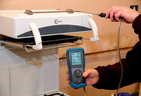
NVQ Diploma Level 3 Gas

        This unit covers                   Introduction
         regulations and                   In this chapter you will be instructed on the standards of chimneys
         standards on flues and            and flue systems that can be used with gas appliances. Flues and
         chimney systems                   chimney systems are an integral part of an appliance’s installation. It is
                                           important that you, as a gas operative, understand the need for them
         classification of                 in the effective removal of the products of combustion, how they are
         chimneys and appliances           constructed and the materials that they can be manufactured from.
         working principles and
         features of open-flued
         systems
         types of open flues               Regulations and standards on flues
         working principles of             and chimney systems
         room-sealed systems
                                           As with all aspects of gas installation work, there are certain standards and
         types of room-sealed
                                           regulations which must be adhered to. With respect to working on flues and
         flues                             chimney systems, there are rules laid out in British Standards (BS) and in the
         testing gas appliance             Gas Safety (Installation and Use) Regulations (GSIUR). There are rules set out
         flue systems                      for the designer, supplier and installer of flue and chimney systems and for
         analysing flue
                                           landlords with regard to their maintenance.
         combustion products               The standard relevant to this area of work is BS 5400 Flueing and ventilation
         before commissioning              for gas appliances of rated input not exceeding 70 kW net (1st, 2nd and
                                           3rd family gases) – Part 1 Specification for installation of gas appliances
                                           to chimneys and for maintenance of chimney and Part 2 Installation and
       Key terms                           maintenance of flues and ventilation for gas appliances. As with other work
       Flue                                on gas, it is essential that persons carrying out work on the flues for gas
       A flue is a passage for conveying   appliances are competent to do so, and any work that is subject to the GSIUR
       the products of combustion to       must comply with these requirements.
       the outside atmosphere.
                                           The building regulation which applies to gas appliances is Approved
       Chimney
                                           Document J (Combustion Appliances and Fuel Storage Systems). This
       A chimney is a structure
       consisting of a wall or walls
                                           document has been updated and came into force on the 1 October 2010.
       enclosing a flue or flues.          Section 1 sets out the general provisions which apply to combustion
                                           installations. For the safe accommodation of combustion appliances, you
                                           must ensure:
                                                 there is sufficient air for combustion purposes and where necessary for
                                                 the cooling of the appliance
                                                 that appliances operate normally without the products of combustion
                                                 (POC) causing a hazard to health (spillage)
                                                 that a device is fitted to warn of carbon monoxide where a fixed
                                                 appliance is installed
                                                 that the appliance operates without causing damage to the fabric of the
                                                 building through heat exposure
                                                 that the appliance and chimney/flue have been inspected and are fit for
                                                 the purpose intended
                                                 that the chimney/flue has been labelled to indicate its performance
                                                 capabilities.

192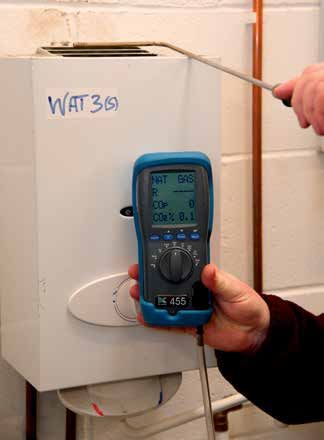
Chapter 7: FLUES AND CHIMNEY SYSTEMS

Exchange of information and planning
The designer or installer of the chimney, and the provider or installer of the
gas appliance should agree and document the important compatibility details
with the customer as appropriate. When erecting a new chimney or chimney
configuration or modifying an existing one, these important details include:
      the type, size and route of the chimney
      the type and size/heat input of the gas appliance that is intended to be
      connected to it.
This is particularly important when different trades are involved in the
erection of the chimney or chimney configuration and the fitting of the
gas appliance.
When you are fitting a gas appliance to an existing open-flue chimney or
room-sealed chimney configuration, it is essential that you confirm that the
chimney is suitable for the appliance. When the chimney is provided as part of
the appliance, for example a room-sealed configuration (including balanced
flue), you should agree and document, with the customer, that the chimney
configuration is suitable for the application. When you are installing either a
new or replacement appliance to an existing chimney/flue configuration you
are responsible for checking that the installation is suitable for the appliance
being installed.

Maintenance of flues
The responsible person (e.g. landlord) should be advised that, for continued
efficient and safe operation of the appliance and its chimney, it is important
that adequate and regular maintenance is carried out by a competent person
(i.e. a Gas Safe registered gas installer) in accordance with the appliance
manufacturer’s recommendations.
The GSIUR impose a general obligation on landlords who provide appliances
in tenanted premises to have them maintained and checked for safety every
12 months.

Classification of chimneys and
appliances
Under the Accredited Certification Scheme (ACS) convention you will be
required to identify types of appliances and category of the flue system. It
is important that you, as a gas operative, are able to undertake this task. It is
your responsibility to know if the appliance is correct for a given situation.
This section informs you of the classification types.

Classification of chimneys
Chimneys are classified according to BS EN 1443:2003, according to the
following performance characteristics:
      temperature class
      pressure class

                                                                                                            193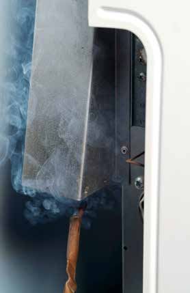
NVQ Diploma Level 3 Gas

                                       resistance to condensate class
                                       corrosion resistance class
                                       soot-fire resistance class (G or O), followed by a distance to
                                       combustibles.
                                Chimney products are specified in the European chimney standards
                                according to the materials which are being used, i.e. concrete, clay/ceramic,
                                metal or plastic.

                                Classification of appliances
                                All appliances are now classified by PD CR 1749:2005; this is the new European
                                standard for the method of evacuation of the POC. It means that the
                                classification of appliances burning combustible gases is the same across the
                                European Community.
                                There are three main types of appliance, grouped according to how they
                                discharge their POC:
                                       Type A Flueless – This type of appliance is not intended for connection
                                       to a flue or any device for evacuating the POC to the outside of the
                                       room in which the appliance is installed. Products of combustion are
                                       released into the room in which the appliance is installed. The air for
                                       combustion is taken from the room.
                                       Type B Open-flued – This type of appliance is intended to be
                                       connected to a flue that evacuates the POC to the outside of the
                                       room containing the appliance. The air for combustion is taken from
                                       the room.
                                       Type C Room-sealed – The air supply, combustion chamber, heat
                                       exchanger and evacuation of POC (i.e. the combustion circuit) for
                                       this type of appliance is sealed with respect to the room in which the
                                       appliance is installed.
                                These types of appliance are then further classified according to flue type, as
                                shown in Table 7.01 opposite.

                                 Progress check
                                 1 Which of the Building Regulations would you refer to for combustion appliances?
                                 2 Complete the following description: ‘Type A Flueless appliances are. . .’
                                 3 Type C appliances are classified as which type of appliance?
                                   a   Flueless
                                   b   Open-flued
                                   c   Room-sealed
                                   d   All of the above
                                 4 Which type of appliance would you install in SE duct or ‘U’ duct systems in the UK?
                                 5 Complete the following requirements: ‘When erecting a new chimney or chimney
                                   configuration or modifying an existing one, the important details shall include . . .’

194
Chapter 7: FLUES AND CHIMNEY SYSTEMS
Letter Classification and Classification and second digit
classification first digit Natural Fan Fan
and type draught downstream upstream
of heat of heat
exchanger exchanger
A – Flueless A1* A2 A2
B – Open-flued B1 – With draught B11* B12* B14 B13*
diverter
B2 – Without draught B21 B22* B23
diverter
C – Room- C1 – Horizontal C11 C12 C13
sealed balanced flue/inlet
air ducts to outside
air
**C2 – Inlet and C21 C22 C23
outlet ducts
connected to
common duct system
for multi-appliance
connections
C3 – Vertical C31 C32 C33
balanced flue/inlet
air ducts to outside
air
C4 – Inlet and outlet C41 C42 C43
appliance connection
ducts connected
to a U-shaped duct
for multi-appliance
system
C5 – Non-balanced C51 C52 C53
flue/inlet air-ducted
system
C6 – Appliance sold C61 C62 C63
without flue/air-inlet
ducts
C7 – Vertical flue to C71 C72* (Vertex) C73* (Vertex)
outside air with air-
supply ducts in loft.
Draught diverter in
loft above air inlet
C8 – Non-balanced C81 C82 C83
system with air-
supply from outside
and flue into a
common duct system
* Common types of flue in the UK.
** Used for SE ducts and ‘U’ ducts systems in the UK.
Table 7.01 Classification of gas appliances according to flue type
195NVQ Diploma Level 3 Gas
Flueless
Type A1
Open-flued types
Type B11 Type B12 Type B13
Type B14 Type B22 Type B23
Figure 7.01 Typical appliances of types A and B
196Chapter 7: FLUES AND CHIMNEY SYSTEMS
Type C11
Multi-storey Multi-storey
Type C12
Type C13
Type C41 U-Duct system
Type C21 SE-Duct system
Figure 7.02 Room-sealed type C appliances
Vertex flue
Room-sealed
vertical discharge
Type C32 Type C33 Type C73
Figure 7.03 Room-sealed type C vertical terminations
197NVQ Diploma Level 3 Gas
Flue liner
Flue Thermal insulation
Flue outer wall
Appliance
connecting
flue pipe
Chimney
Heating
appliance
Progress check Figure 7.04 Chimney components
1 Which of the Building
Regulations would you refer
to for combustion appliances? Working principles and features of
2 Complete the following
description: ‘Type A Flueless
open-flued systems
appliances are. . .’
Open flues are still an integral part of appliance installation, in particular
3 Type ‘C’ appliances are when fitting space heating appliances (gas fires). You need to understand the
classified as which type of
importance of ensuring that the flue is correct for the installation.
appliance:
a Flueless
b Open-flued Type B Open-flued (natural draught)
c Room-sealed
Natural draught systems take combustion air from the room and the POC
d All of the above
travel up the flue by natural draught or ‘flue pull’. This is caused by the
4 Which type of appliance difference in the densities of hot flue gases and the cold air outside.
would you install in SE duct or
‘U’ duct systems in the UK? The strength of the flue pull or draught is increased when the flue gases are
5 Complete the following hotter or if the flue height is increased. Factors that will slow down the flue
requirements: ‘When erecting pull are 90 o bends and horizontal flue runs, so these must be avoided.
a new chimney or chimney
configuration or modifying an This flue draught is created by natural means and is quite slight, so it is important
existing one, the important to design/install a flue carefully to allow for the necessary up-draught. Fans
details shall include… ’ can be fitted in flues to overcome problems and allow more flexibility. See the
section on ‘Type B Open-flued forced (fanned draught)’ on page 201.
198Chapter 7: FLUES AND CHIMNEY SYSTEMS
Hot gases rising
Height
Terminal
Figure 7.05 Flue draught
Secondary flue
Open flues are sometimes referred to as ‘conventional flues’ and have four Draught diverter
main parts:
primary flue Primary flue
draught diverter
secondary flue
terminal. Appliance
Both the primary flue and draught diverter are normally part of the appliance,
while the secondary flue and terminal are installed on the job to suit the
particular position of the appliance.
The primary flue creates the initial flue pull to clear the POC from the
combustion chamber. Figure 7.06 Four main parts of a flue
Diluted Down draught
products air
Air
supply Products
and air
Products Products
of combustion of combustion
Figure 7.07 Section through a draught diverter
199NVQ Diploma Level 3 Gas
The draught diverter:
diverts any downdraught from the secondary flue from the combustion
chamber of the appliance, as this can interfere with the combustion
process
allows dilution of flue products with air
breaks any excessive pull on the flue (i.e. in windy weather), as this can
also interfere with the combustion process.
Where a draught diverter is fitted it should be installed in the same space as
the appliance.
The secondary flue passes all the POC up to the terminal and should be
constructed in such a way as to give the best possible conditions for the flue
to work efficiently. Resistance of the installed components should be kept to a
minimum by:
avoiding horizontal/shallow runs
keeping bends to a minimum of 45 °
keeping flues internal where possible (warm)
providing a 600 mm vertical rise from the appliance to the first bend
fitting the correctly sized flue – at least equal size to the appliance
outlet and as identified by the manufacturer.
The terminal is fitted on top of the secondary flue. Its purpose is to:
help the flue gases discharge from the flue
prevent rain, birds and leaves etc. from entering the flue
minimise downdraught.
You should fit terminals to flues with a cross-sectional area of 170 mm or less.
The terminal needs to be suitable for the appliance type fitted to the flue.
Terracotta chimney rain inserts are not suitable for use with gas appliances.
Only use approved terminals, as these have been checked for satisfactory
Figure 7.08 Acceptable terminals
200Chapter 7: FLUES AND CHIMNEY SYSTEMS
Figure 7.09 Unacceptable flue terminals
performance and have limited openings of not less than 6 mm but not more
than 16 mm (except for incinerators, which are allowed 25 mm). Figures 7.08
and 7.09 show examples of acceptable and unacceptable types of terminals
for use with certain flue systems.
Type B Open-flued forced (fanned draught)
Fanned draught flues allow for greater flexibility in the positioning of the
appliance. There are two types of fanned draught flue systems:
where the fan is an integral part of the appliance (positive pressure)
where a fan is located in the outlet to a chimney or flue system
(negative pressure) and has been specified or supplied by the appliance
manufacturer.
Where the fan is not factory fitted, always connect it to the appliance in
accordance with the appliance manufacturer’s instructions. Do not make
any modifications to the appliance without the agreement of the appliance
manufacturer.
When fitting a fan in the chimney/flue system, ensure the fan size allows for
full clearance of POC against adverse wind pressures. This also includes the
route which the chimney/flue must take and requires you to calculate the
resistance to flow (including the specified adverse pressure) at the design
flow rate and to compare it with the pressure available from the chosen fan.
The responsibility for safe installation lies with the installer and the appliance
manufacturer.
Proprietary fan kits are available from manufacturers and include fail safe
features to prevent the appliance from operating should the fan fail.
Minimum flow rates for fanned flues
Appliances Maximum CO2 Minimum flue flow rate
concentration (%) (m3/h per kW input*)
Gas fire 1 10.7
Fire/back boiler 2 5.4
All other appliances 4 2.6
* These figures refer to natural gas.
Table 7.02 Minimum flow rates for fanned flues
Table 7.02 may be used to calculate flue velocity although care is required to
relate a specific measured velocity to a mean volumetric flue flow rate. The
201NVQ Diploma Level 3 Gas
final test for correct operation of a chimney is a spillage test at the appliance.
For decorative fuel effect gas appliances you should refer to BS 5871-3.
Safety control
Where fans are fitted in secondary chimneys/flues they should incorporate
a safety control in the secondary flue which is external to the appliance. The
safety device should be capable of cutting off the flow of gas to the main
burner if the flow in the secondary flue becomes insufficient for more than
6 secs.
The safety control means the flue flow sensor must be in the ‘no flow’ position
before the fan can be set in operation. Should the safety control be activated
then manual intervention is required to re-establish the gas supply to the
main burner, unless the appliance incorporates a flame supervision device
(FSD) and the correct flue flow is re-established.
Types of open flues and chimneys
There are certain considerations that must be taken into account when
fitting new chimneys and open flues, including the construction materials
of the flue/chimney and their suitability for the particular appliance and
circumstances.
Always read the manufacturer’s instructions to check if the appliance is
suitable for the flue it is being installed with.
Chimney construction materials
Where new open-flued appliances are fitted, the chimney should be
designed to comply with BS EN 15287-1 Chimneys – Design, installation
and commissioning of chimneys (Part 1: Chimneys for non-room-sealed
heating appliances). These chimneys are classified as being allowed by the
manufacturer. New chimneys can be classed as system chimneys or custom-
built chimneys.
Chimney/flue construction materials must now be capable of removing
condensed combustion products which are mildly acidic. Materials such as
copper, mild steel and lower grades of stainless steel are not suitable for this
type of application.
Where a new chimney is being installed, the chimney should be constructed
from either brick (or other masonry) or flue blocks. Brick/masonry chimneys
should be lined with clay liners conforming to BS EN 1457 or concrete liners
conforming to BS EN 1857. Poured concrete linings are not acceptable as
a method of lining new masonry chimneys. Flue block chimneys should
be lined with clay conforming to BS EN 1806 or concrete conforming to
BS EN 1858.
Rigid flues
Where factory-made insulated metal chimneys are used, they must conform
to BS EN 1856-1. If they are single walled then they must not be used
externally. When chimneys are used externally, they must be twin walled to BS
EN 1856-1 and installed to manufacturers’ instructions.
202Chapter 7: FLUES AND CHIMNEY SYSTEMS
Rigid metallic flues
Twin-wall metal flues
Twin-walled metal flues are available in a variety of lengths and diameters,
with a vast range of fittings and brackets to suit every installation. You should
consult the manufacturers’ information booklets to familiarise yourself with
the range of products available before deciding which to fit.
Flue pipe
25 mm min.
Metal floor plate
Timber flooring
Light sheet metal
Plasterboard
Non-combustible
material acting as Metal ceiling plate
fire-stop
Figure 7.10 Flue passing through combustible material
There are two types of twin-walled flues: fully insulated or with an air gap.
Twin-walled flues with an air gap are only suitable for use internally but can
be used externally for lengths less than 3 m. For all other external situations
fully insulated twin-walled pipe should be used.
The joints are designed to be fitted with the ‘male’ or spigot end uppermost.
Where a pipe passes through a combustible material like a floor/ceiling, a
sleeve must be provided to give a minimum circular space of 25 mm (see
Figure 7.10).
Where a flue pipe passes through a tiled sloping roof (see Figure 7.11 on
page 204), a purpose-made weathering slate is required with an upstand of
150 mm minimum at the rear of the slate. Aluminium weathering slates are
also available to purchase. You should always consult the manufacturer’s
instructions before fitting the weathering slate.
Vitreous-enamelled steel flues
A vitreous-enamelled steel flue is a single-skin pipe available in many
lengths and sizes, although it can be cut to any length. It is often used as
the connection between an appliance and the main flue, and may include a
disconnecting collar to allow appliance removal. The socket on single-wall
pipe is fitted uppermost, unlike the twin-wall.
203NVQ Diploma Level 3 Gas
Weathering
collar
Weathering 150 mm upstand
slate
Insulating sleeve
Figure 7.11 Flue passing through sloping roof
Asbestos flues
Under no circumstances should asbestos cement materials be used for new
flue pipes. Where an existing chimney is suspected to be made of asbestos
cement or contain asbestos then a risk assessment must be conducted prior
to carrying out any work. See the section on ‘Risk assessments’ (page 62).
You should only reuse an existing asbestos cement chimney or chimney
component if it is sound and does not require cutting or machining. More
information regarding asbestos-related products can be found on the
HSE website.
Pre-cast concrete flue blocks
Pre-cast concrete flue blocks are the same size and shape as a house brick
and can therefore be built into (or ‘bonded’ with) the walls of a new property
during construction. Non-bonded blocks are available and are more suited to
existing properties.
You must use flue blocks certified to BS EN 1858 and fit them to the
manufacturer’s instructions. Excess cement should be carefully removed from
the block during construction and no air gaps should be left.
All flue blocks must be laid spigot end up with a 3mm thick complete and
gas-tight joint. The most convenient method of jointing is to apply cartridges
of ready-mixed high-temperature mortar with a cartridge gun. Always use the
nozzle and cut it 35 mm from the end to give an 8 mm bead. Before jointing,
ensure the upper face of the block is dry and clear of debris.
Particular attention should be given to the connection from the flue blocks
to the ridge terminal; the flue pipe installed should be of twin-wall insulated
204Chapter 7: FLUES AND CHIMNEY SYSTEMS
Plain block Cover block
T
W
T L B
L = flue breadth
W = flue width
T = wall thickness
Lateral offset block B = bonding extension
W
Rear offset block Starter block
Transfer block (different projections)
Figure 7.12 Flue blocks
pipe construction using the correct fittings. When a metal chimney is
connected to a flue block system then a transfer block must be used. When
making the connection, be sure not to let the metal flue component project
into the flue as this would cause a restriction of the cross-sectional area of the
flue system.
Flue block chimneys should not be directly faced with plaster, as the heat
will cause the plaster to crack. They should be faced with either concrete (or
similar material) blocks or with plasterboard. Where plasterboard is used as
dry lining, the dabs or batons should not be in direct contact with the flue
blocks. You must also ensure that no fixing devices penetrate the blocks and
that the joint between the facing and the blocks is sealed around the fireplace
opening. An example is where plasterboard has been fitted and the gap
between the blocks and the plasterboard must be sealed to prevent POC from
escaping between the gap.
Where a new chimney is constructed using flue blocks, the minimum cross-
sectional area should not be less than 16,500 mm2 with no dimension less
205NVQ Diploma Level 3 Gas
than 90 mm. There are, however, appliances which cannot be connected to
flue blocks which have a cross-sectional area between 12,000 mm2 and
13,000 mm2 or a minor dimension of 63 mm or less. These are:
drying cabinets
appliances having a flue duct outlet area greater than 13,000 mm2
gas fires and combined appliances incorporating a gas fire, unless
a special starter block/adapter has been designed for the purpose,
tested and supplied by the appliance manufacturer or the appliance
manufacturer’s instructions specifically state that this is acceptable.
Some manufacturers state that their appliances are not suitable for
connection to flue block systems of certain sizes constructed to BS 1289:1975.
Further guidance is given in BS 5440 – Part 1:2008.
Figure 7.13 below shows a detail of a completed installation with flue blocks.
Pre-case flue blocks can have a bad reputation for poor flue performance and
spillage of the POC. This is because they have been badly installed in the past.
As with any open flue, always ensure that a thorough visual inspection of the
flue system is conducted. You should be particularly careful when measuring
the cross-sectional area to ensure accuracy, and always conduct adequate
spillage tests prior to handover.
Secondary flue, must be twin walled
Roof space 4
3
3
3
3
3
3
3
1 = starter block
3
2 = lintel cover block
3
3 = plain bonding block
3
3 4 = offset transfer block
3 5 = lateral offset block
3
First floor 3
5
5
5
3
3
3
3
3
2
1 May be produced as
1
one- or two-piece set
1
Figure 7.13 Complete flue-block installation
206Chapter 7: FLUES AND CHIMNEY SYSTEMS
Figure 7.14 Terminal ridge tile
300 mm minimum 1.5 m minimum
Figure 7.15 Positioning of ridge vents
Other types of open flue
Flexible stainless steel flues – liners
Flexible stainless steel flues must comply with BS EN 1856-2. They are used
internally to line existing flues that do not have a suitable clay lining as part
of the original building construction. Liners are also used when the existing
chimney or flue has given unsatisfactory performance in the past.
Liners must be installed in one continuous length and not be joined to reach
the required length. Any bends in the liner must be of a maximum of 45 o and
there should be no kinks or tears present.
It is essential to secure liners with a clamp plate and to seal the top and the
base of the chimney. A sealing plate must be included at the base of the flue
system to prevent debris from falling into the appliance opening and onto
the appliance. Where the diameter of the flue is less than 170 mm, use an
approved terminal to protect the end of the liner.
207NVQ Diploma Level 3 Gas
1
2
3
4 5 6 7
Key
1 Flue liner conforming to BS EN 1856-2
2 Joints to be well made where the closure plate or the flue box is sealed to the face of the opening or
fire surround
3 Debris or register plate
4 Flue liner connected to a proprietary flue gas collector. For use with an appliance with a closure plate
5 Flue liner conforming to BS EN 1856-2 connected to a gas flue box conforming to BS 715
6 Flue liner secured and sealed into a proprietary gather above the builder’s opening
7 Flue liner mechanically secured and sealed with a clamp to a debris or register plate above a
builder’s opening
Figure 7.16 Connections for flexible stainless steel liner
The liner should not project more than a nominal 25 mm below the plate.
Where gas supplies are to be made through the wall of a gas flue box (4 and
5, Figure 7.16) it should be routed as close as practicable to the bottom of the
box and sealed with non-setting sealant.
Where flexible liners are connected to the tops of flue boxes they should rise
as near vertical as possible no angle should be any greater than 45 o. The
correct method of connecting flexible flues to a gas fire back boiler is shown
in Figure 7.17 – note the disconnection socket and the sealing plate.
A typical way of sealing the annular space between the chimney and the
flexible flue liner would be with mineral wool. For larger openings, it might
be necessary to use, for example, a register plate to hold the mineral wool in
place. Follow the advice given by the liner manufacturer, particularly in relation
to the location of the liner where it passes around bends in the chimney.
208Chapter 7: FLUES AND CHIMNEY SYSTEMS
Flue liner
Flue sealing plate
Fire flue Flue connection
connection socket
Louvres
Boiler flue hood
Gas fire
Sealed to wall Boiler heat
exchanger
Fire guard
Burner
Access to controls and
passage for combustion air
Boiler controls
Figure 7.17 Sealing plate at base of flue liner
Unless otherwise stated by the manufacturer, decorative fuel effect fires must
be installed with a minimum flue size of 175 mm diameter.
When chimneys exceed certain lengths, they may need to be lined,
depending on the type of appliance fitted, as shown in Table 7.03.
Appliance type Flue length
Gas fire > 10 m (external wall)
> 12 m (internal wall)
Gas fire with back boiler Any length
Gas fire with circulator > 10 m (external wall)
> 12 m (internal wall)
Circulator > 6 m (external wall)
> 1.5 m (external length and total length > 9m)
Other appliance Flue lengths greater than in Table 7.05 (see page 213)
Table 7.03 Required flue lining for different appliances
209NVQ Diploma Level 3 Gas
Shared flues
In special cases you are allowed to connect two or more appliances into
the same flue, but special rules apply. BS 5440 Part 1:2008 identifies six
important rules:
Each appliance shall have a draught diverter.
Each appliance shall have a flame-supervision device.
Each appliance shall have a safety control (an atmospheric sensing
device) to shut down the appliance before there is a dangerous quantity
of POC in the room.
The flue must be sized to ensure complete removal of the products of
the whole installation.
The chimney must have access for inspection and maintenance.
All appliances shall be in the same room or space or on different floors
as below.
Type of appliance Nominal cross-section area of main flue
2
Greater than 40,000 mm but less than 62,000 mm2 or more
62,000 mm2
Maximum number Total input rating Maximum number Total input rating
of appliances (kW) of appliances (kW)
Gas fire 5 30 7 45
Instantaneous water
10 300 10 450
heater
Storage water heater,
central heating unit 10 120 10 180
or air heater
Table 7.04 Appliances discharging by way of subsidiary flue into a main flue
Where appliances are to be installed on different floors using the same shared
flue then the following rules apply:
The main chimney must not to be part of an external wall.
The nominal cross-sectional area of the main flue serving two or more
appliances should be no less than 40,000 mm2 and should be sized as
detailed in Table 7.05 on page 213.
Each appliance is to discharge into the main flue by way of a subsidiary
flue
— the connecting pipe is to be not less than 1.2 m above the outlet of
the appliance
— the connection shall be a minimum of 3 m above the outlet of the
appliance where it is a gas fire.
Where chimneys are newly built all appliances are to be the same type.
When connecting to an existing chimney replacements are to be of the
same type and not greater in input to the original appliance.
Fanned-flued appliances of Types B14, B22, B23 should not be used.
All appliances connected to the flue must be labelled to indicate that
they are on a shared flue system.
210Chapter 7: FLUES AND CHIMNEY SYSTEMS
1
Key 2
3
1 Main flue (serving
6th to 10th floor} 5
2 Single flue (serving 11th
11th floor)
3 Main flue (serving Combined unit
10th
ground to 5th floor)
4 Subsidiary flues 4
9th
5 Shared flue (serving
10th and 11th floors)
8th 1
6 Main flue (serving
ground to 9th floors)
7th
7 Opening to subsidiary flue Gather unit
6th 7
5th 3
6
4th
Entry unit 3rd
2nd
1st
Bearer unit
Flue block types Shared chimney for gas fires Shared chimney for gas fires
or water heaters
Figure 7.18 Shared flues
Flue boxes
Flue boxes funnel the POC into the flue system and can be fitted to the
back of:
radiant convector gas fires
insert live fuel effect gas fires
decorative fuel effect gas fires
combined gas fire and back boilers
gas heating stoves.
211NVQ Diploma Level 3 Gas
Flue boxes must not be installed in solid fuel appliances. Check with
manufacturer’s instructions if the gas appliance can be used with gas flue
box systems. Flue boxes are used in builder’s openings or in a purpose-built
chimney without bricks or masonry.
Flue boxes are manufactured to BS 715 and can be of single-wall or insulated
twin-wall construction. All joints are sealed to prevent leakage of POC.
The type of flues which connect to these can be either metallic flexible flue
liner to BS EN 1856-2 or double-walled chimney/flue system to BS EN 1856-1.
Considerations when installing open flues
When an open flue is installed you must take into account the type of
material, the length of the flue and the exposure of the flue.
Condensation
An open flue should be installed to keep flue gases at their maximum
temperature and avoid problems of excessive condensation forming in the
2000 2000
1990 2008 amended 2002
Measurement positions
to BS 5440-1 Prohibited zones
Roof light
L/L Dormer
B/B
P/P
K/K
F/F
E/E
M/M
N/N
G/G
Q B/B
60
0m
D/D
m
B C/C
zo
A/A
ne
Roof angle H/H
J/J
greater than 45°
A D
C
Flat roof
Roof angle extension
less than 45°
Figure 7.19 Open-flued terminal positions
212Chapter 7: FLUES AND CHIMNEY SYSTEMS
flue. This is why single-wall flues are not allowed to be installed externally
except where they project through a roof, and why twin-wall flues, with only
an air gap for insulation, are only allowed up to 3 m in length when used
externally.
Table 7.05 shows the maximum lengths of open flue to be used with a gas fire
in order to avoid condensation.
Condensate-free length
Flue 2 125 mm flue pipe
exposure 225 mm brick chimney or pre-cast
concrete block flue of 1300 mm2 * Single wall Double wall
Internal 12 m 20 m 33 m
External 10 m Not allowed 28 m
* See BS 5440-1 for more details.
Table 7.05 Maximum lengths of open flue used with a gas fire in order to avoid condensation
Terminal positions
It is important that you understand the positioning of open-flued appliance
terminal positions. This is important when you are servicing or maintaining
appliances which have been in a number of years. Table 7.06 indicates the
positioning requirements from earlier editions of the standards (BS 5440-1).
Minimum (mm)
Roof position, angle or situation BS 5440–1 Version
2008 2000 1990
o
A/A/A Roof angle greater than 45 1,500 1,500 1,500 1000
B/B/B Roof angle greater than 45 o 1,500 1,500 1,500 1000
C/C/C Roof angle less than 45 o 1,500 1,500 1,500 600
D/D/D Roof angle less than 45 o 1,500 1,500 1,500 600
E/E Between ridge terminals 1,500 1,500 1,500 600
F/F Ridge terminal to a higher structure 300 300 300
G/G Prohibited zone 2,300 2,300 2,300
H/H Flat roof extension 600 600 600
Between edge of flat roof structure and dwelling. Either 10,000
J/J least least greater
mm along flat roof or to edge of structure which is ever the:
K/K Where distance ‘K’ between flue and dormer is less than 1,500 1,500 1,500 1,500
L/L Above dormer 600 600 600 600
M/M Prohibited zone from a roof light downwards 2,000 2,000 2,000
N/N Prohibited zone from a roof light either side 600 600 600
P/P Prohibited zone from a roof light upwards 600 600 600
Q Above the ridge of a roof 600
Table 7.06 Open-flued terminal position measurements
213NVQ Diploma Level 3 Gas
B
B
A A
A
A
A
B
A = 600 mm
B = 2000 mm
If A is less than 600 mm Flue not to penetrate shaded area of roof
then B to be not less than 600 mm
Figure 7.21 Minimal terminal distances – adjacent to windows or openings
Figure 7.20 Locations of terminals for pitched roof with structures on pitched roof
Figures 7.20 and 7.21 illustrate acceptable open-flued terminal positions.
Please note that measurements are taken from the bottom of the terminal.
Prohibited zones
There are prohibited zones on or adjacent to buildings where open flues must
not terminate, primarily to prevent downdraught and reversal of the flue-pipe
operation, which would spill the POC into the building. Figures 7.22 and 7.23
show where flues must not be sited.
Prohibited zone 2300 mm
600 mm
Edge of roof of flat-
roof extension or
10,000mm along from
600 mm
the structure,
whichever is the
greater
These walls may be
part of same
10,000 mm building or adjacent
buildings
Figure 7.22 Example of prohibited zone near adjacent building
214Chapter 7: FLUES AND CHIMNEY SYSTEMS
Elevation Progress check
Prohibited zone Prohibited zone
1 The secondary flue passes all
the POC up to the terminal.
600 mm List the key points to prevent
resistance in the flue.
2 Manufacturers of fanned-
600 mm
draught flues provide
propriety fan kits which
2300 mm 2300 mm include safety controls to
prevent the appliance from
operating should the fan fail.
What should the safety device
Plan be capable of doing?
3 Where a new chimney
is being utilised for gas
appliances it must be lined
with materials which are
manufactured from which
materials and to which
standards?
Figure 7.23 Prohibited zones for flues
To protect against the problems of downdraught where appliances are fitted
to flues that exit through a steeply pitched roof, it is recommended that the
route of the chimney is diverted to an outlet at the highest point on the roof,
rather than terminating on the slope of the roof.
Working principles of room-sealed
systems
While open-flued appliances can be difficult, as the route and terminal
position are critical to ensure that safe dispersal of the products occurs and
vents can easily be blocked or restrict the provision of air for combustion,
room-sealed or ‘balanced flue’ appliances don’t have such difficulties.
Fan
Flue gases
Air duct Air
Flue duct Flue gases
Air Air in
Burner
Figure 7.24 Principles of balanced flue operation
215NVQ Diploma Level 3 Gas
Air for combustion in a room-sealed or balanced-flue appliance is taken
directly from outside and, as the name implies, the appliance is ‘room-sealed’,
so there is no danger of POC entering the room.
Room-sealed appliances are therefore preferable to open flues. The flueing
options are increased greatly with these types of appliance where a fanned
flue system is chosen.
Terminating room-sealed systems
Room-sealed systems must be fitted within the vicinity of an external wall
or roof termination. It can be seen in Figure 7.24 that the POC outlet and
the air intake are at the same point and are therefore at equal pressure,
whatever the wind conditions. This is why it is called ‘balanced’ flue. The
special terminal that is part of the appliance must be fitted in such a
position so as to:
prevent products from re-entering the building
allow free air movement
prevent any nearby obstacles causing imbalance around
the terminal.
BS 5440 Part 1 details acceptable positions for flue terminals on buildings, as
shown in Figure 7.25 (larger appliances need greater distances).
P
I O
O
D&E
F O
L B C
J
N
O M
G A H
N
H
M
K
Figure 7.25 Positions for balanced flue terminals
216Chapter 7: FLUES AND CHIMNEY SYSTEMS
Dimension Terminal position Heat input (kW net) Natural draught Fanned
draught
A – see note 1 Directly below an opening, air brick, 0–7 kW 300 mm 300 mm
opening window, door etc. >7–14 kW 600 mm 300 mm
>14–32 kW 1,500 mm 300 mm
>32–70 kW 2,000 m 300 mm
B – see note 1 Above an opening, air brick, opening 0–7 kW 300 mm 300 mm
window, door etc. >7–14 kW 300 mm 300 mm
>14–32 kW 300 mm 300 mm
>32–70 kW 600 mm 300 mm
C – see note 1 Horizontally to an opening, air brick, 0–7 kW 300 mm 300 mm
opening window, door etc. >7–14 kW 400 mm 300 mm
>14–32 kW 600 mm 300 mm
>32–70 kW 600 mm 300 mm
D Below gutters, drain pipes or soil pipes 0–70 kW 300 mm 75 mm
E Below eaves 0–70 kW 300 mm 200 mm
F Below balconies or car-port roofs 0–70 kW 600 mm 200 mm
G From a vertical drain pipe or soil pipe 0–70 kW 1,500 mm –
see note 4
H – see note 2 From an internal or external corner 0–70 kW 600 mm 300 mm
I Above ground, roof or balcony 0–70 kW 300 mm 300 mm
J From a surface facing a terminal – see 0–70 kW 600 mm 600 mm
note 3
K From a terminal facing a terminal 0–70 kW 600 mm 1,200 mm
L From an opening in the car-port into 0–70 kW 1,200 mm 1,200 mm
the dwelling
M Vertically from a terminal on the same 0–70 kW 1,500 mm 1,500 mm
wall
N Horizontally from a terminal on the 0–70 kW 300 mm 300 mm
same wall
O Above intersection with the roof 0–70 kW N/A Manufacturer’s
instructions
P Between a chimney and a ridge 1,500 mm (300 mm
terminal between similar
ridge terminals)
Note 1
In addition the terminal should not be closer than 150 mm (fanned draught) or
300 mm (natural draught) from an opening in the building fabric for the purpose of
accommodating a built-in element such as a window frame.
Note 2
This does not apply to building protrusions less than 450 mm, e.g. a chimney or an
external wall, for the following appliance types: fanned draught, natural draught up
to 7 kW, or if detailed in the manufacturer’s instructions.
Note 3
Fanned-flue terminal should be at least 2 m from any opening in a building that is
directly opposite and should not discharge POCs across an adjoining boundary.
Note 4
This dimension may be reduced to 75 mm for appliances up to 5 kW (net) input.
Table 7.07 Balanced flue terminals
217NVQ Diploma Level 3 Gas
Note that the outlet part of the terminal can become quite hot, and therefore
a guard must be fitted if the terminal is within 2 m of ground level or if
persons have access to touch it, e.g. on a balcony.
Take special care when fitting room-sealed flues through walls, particularly
in timber-framed buildings to protect against fire. As always, follow the
manufacturer’s instructions carefully.
Terminals for room-sealed flues or fanned draught open flues must be
positioned to ensure the safe dispersal of flue gases. In general this means
that no terminal should be located more than 1 m below the top level of a
basement area, light well or retaining wall. The products must discharge into
free open air. Further guidance is given in BS 5440.
Balanced compartments
The balanced compartment is a method of installing an open-flued appliance
in a room-sealed situation and arranging the chimney and ventilation so that
a balanced flue effect is achieved.
This method is useful where higher rated appliances are installed. This
method can also be an alternative to longer external flues, or can be used
where a boiler is housed in an adjacent boiler house to a tall building.
The chimney outlet location in Figure 7.26 is only suitable for balanced
compartment applications and is not to be used for other open-flue
installations.
300 mm
No more than
150 mm
Air
inlet
Double walled
chimney/flue
Electrical isolation
switch
Fixed notice
Self-closing
door
Draught
sealed 300 mm
Figure 7.26 Non-proprietary balanced compartment
218Chapter 7: FLUES AND CHIMNEY SYSTEMS
When a proprietary system is used, as in Figure 7.27, then the systems
manufacturer’s instructions should be followed.
Balanced compartments must have:
a self-closing flush door with a draught-sealing strip
a door that should not open into a room containing a shower or bath,
or where the appliance has a rated input greater than 12.7 kW (14
kW gross) and the door is opening into a room intended for sleeping
accommodation
a notice attached to the door stating that the door must be kept closed
no other ventilation opening in the compartment other than those
designed
a door opening fitted with a switch that acts as an electrical isolator,
shutting down the appliance when the door is opened
twin-wall insulated pipes flue pipes to BS EN 1856-1
insulated any exposed hot water pipework to a minimum thickness of
19 mm in order to minimise heat transfer within the compartment.
In addition, the chimney and ventilation should ensure the full clearance of
the POC. The supply duct (air inlet) terminal should be no more than 150 mm
from the base of the chimney outlet.
Where the air is ducted to a low level, i.e. 300 mm or less from the floor (see
Figure 7.26) within the balanced compartment, the cross-sectional area of the
air supply duct should be not less than 7.5 cm2 per kW (net) of the appliance
maximum rated input. Maximum rated input is calculated from 1.5 times the
allowance for the maximum air vent area for a high level, direct to outside air
opening specified for open-flued appliances in BS 5440-2.
Terminal
Weathering to
air intakes
Air intakes protected
600 mm
by bird-wire guards
No other openings
into compartment
Insulated
flue
Self-closing door
with notice
Open-flued
appliance
Figure 7.27 Balanced compartment
219NVQ Diploma Level 3 Gas
Where the air is ducted to a high level only (see Figure 7.27) within the
balanced compartment, the cross-sectional area of the air supply duct shall
be not less than 12.5 cm2 per kW (net) of the appliance maximum rated input.
This is calculated from 2.5 times the allowance for the maximum air vent
area for a high level, direct to outside air opening specified for open-flued
appliances in BS 5440-2.
Types of room-sealed flues
Shared flues
Shared flues are mainly for use in multi-storey buildings, but since you may
work on an appliance in a domestic flat, it is important that you recognise
the main features.
The two types of system are the SE duct and the ‘U’ duct, as shown below in
Figure 7.28.
Appliances used in these type of ducts are specially adapted versions of room-
sealed flue appliances which are fitted into the vertical flue and air duct on
each floor. Only types C2 and C4 appliances are suitable for use. Replacement
appliances must be of the same type and suitably labeled, stating that they
are fitted to a shared flue.
Products of
combustion
Products of
combustion Air inlet
Products
outlet
projects
25 mm
Air
inlet
flush
Air inlet
Figure 7.28 SE duct (on left) and ‘U’ duct (on right)
220Chapter 7: FLUES AND CHIMNEY SYSTEMS
The responsibility for the shared flue itself is that of the landlord or the person
responsible for the building. Annual checks need to be carried out on the
shared flue.
Only type C2 appliances should be connected to a SE duct or ‘U’ duct chimney
(where the flue duct and air supply duct of the appliance are connected into
the same common duct of the chimney) in accordance with the appliance
manufacturer’s installation instructions.
Only a C4 appliance should be used with the shared chimney where the flue
duct and the air supply duct of the appliance are connected to separate
common ducts of the shared chimney.
Fanned flue
Condensing boilers are normally of the fanned-flue type and are becoming
more popular, owing to their increased efficiency. These appliances have
a tendency to form a plume of vapour from the flue terminal – you should
take this into account when siting the appliance. You should also consider
the disposal of condensate and follow manufacturer’s instructions. Typical
condensate drainage is discharged in plastics which are to be solvent welded
(MUPVC) to avoid corrosion problems, and the position of termination may be
to internal or external discharge stacks with a trap fitted, and where no stack
or drain gulley is available to soak away.
Vertex flues (type C7)
Vertex flues are unusual, with the air supply being taken from the roof space.
The secondary flue is connected to a draught break in the attic which should
be ventilated to the standard of current Building Regulations. The draught
break must be at least 300 mm above the level of any insulation, and the
flue above the break should be vertical for at least 600 mm before any bend
is used.
Vertex type appliances
Consider the following guidance where a chimney for a Type C7 (‘Vertex’)
appliance is used (the primary flue and draught break are both parts of the
appliance):
install in accordance with the instructions provided by the appliance
manufacturer
install the secondary flue connected to the appliance draught break
in the roof space in accordance with the instructions provided by the
chimney manufacturer
make provision for an adequate unobstructed air supply to the roof
space in which the draught break is located
make sure the secondary flue connected to the appliance draught
break is constructed of a non-corrosive material such as stainless steel
and is vertical
if a change of direction (offset) is unavoidable, the first section of the
chimney above the draught break should rise vertically by a minimum
of 600 mm before it changes direction
221NVQ Diploma Level 3 Gas
Progress check Terminal Ridge tile
through roof
1 At what height above a
dormer window should an
open-flued appliance terminal
finish?
a 300 mm
b 600 mm
c 1,100 mm
d 1,500 mm
2 By how much is the
prohibited zone to the side of
Bend options
a roof light?
as and when
a 300 mm required
b 600 mm
c 900 mm
d 1,200 mm
3 Complete the following
statement: ‘To prevent Combustion air
min.
300 mm
downdraught where intake
appliances are fitted to
flues that exit through
steeply pitched roofs it is
recommended that. . .’
4 If an 11 kW fanned flue boiler
terminates above an air
brick, what is the minimum
measurement above the air
brick that the flue should
terminate? Appliance
5 How far from an opening
directly opposite a fanned
flue should the outlet be
terminated? Figure 7.29 Vertex flue
make provision to collect and remove any condensate that may form
above the draught break
ensure the draught break is at least 300 mm above the level of the
insulation in the roof space
conduct a spillage test in accordance with the manufacturer’s
instructions at the draught break in the roof space (see the section on
‘Checks with appliance connected (spillage test)’, page 225).
The ventilation design parameters should be considered and any roof
ventilators should be checked to ensure they are unobstructed by
insulation, etc.
Testing gas appliance flue systems
Regulation 26(1) of the GSIUR states:
26(1) No person shall install a gas appliance unless it can be used without
constituting a danger to any person.
222Chapter 7: FLUES AND CHIMNEY SYSTEMS
Approved Code of Practice 26(1) also gives guidance that, as a gas operative,
you should ensure that any appliance you install, or flue to which you connect
an appliance, is safe for use. You should ensure requirements in Appendix 1 of
the GSIUR are met, as applicable, and refer to the appropriate standards.
It is essential, then, that you inspect and test any flue for gas appliances,
not just at installation but each time the appliance is worked on, including
service/maintenance. It is necessary to carry out checks on the complete flue
system, as follows.
Inspection and tests for open-flued systems
Building Regulation Document J (Appendix E) gives guidance on the testing
of natural draught flues, both existing and new. These procedures only apply
to open-flued appliances and are only used to assess whether the flue in the
chimney, the connecting flue pipe and the flue gas passage in the appliance
START
NO Carry out a visual inspection of
Rectify flue defects
the flue, including the flue
before proceeding
termination and route
YES
NO Is there sufficient ventilation
Provide ventilation in accordance
for combustion and the
with manufacturer’s instructions
operation of the flue?
YES
NO
Investigate cause, suspect cold Flue flow test. Does it pass?
or blocked flue
YES
Investigate cause, suspect
downdraught or thermal inversion. NO
Spillage test. Does it pass?
Use an anti-downdraught terminal
in instances where there are
intermittent downdraughts YES
Commission re-instate
the appliance
Figure 7.30 Open-flue testing sequence flow chart
223NVQ Diploma Level 3 Gas
are free from obstruction and are acceptably gas tight. The procedure for flue
testing is also outlined in BS 5440 Part 1. Where possible, test flues at the most
appropriate time during the building work and before any finishing coverings
have been applied e.g. plaster or dry-lining boards.
Methods of testing open-flued systems involve a visual check, and spillage
and flow tests.
Visual inspection
Visual inspections are covered in 6.3.2.1 of BS 5440 Part 1.
The chimney, whether existing, newly erected, adapted or altered, should be
visually checked before you fit an appliance. You should ensure it is fit for the
intended use with the intended appliance, and:
is unobstructed, complete and continuous throughout its length
serves only one room or appliance
has the terminal correctly sited and a weather-tight joint between the
terminal and the chimney
any dampers or restrictor plates have been removed or permanently
fixed in the open position to leave the main part of the flue
unobstructed
any catchment space is the correct size, free of any debris and any gaps
into the catchment space are sealed from the surrounding structure
where an existing chimney has been used, any signs of spillage should
be investigated and faults rectified.
In addition to the above:
Inspect the loft space to ensure that any chimney passing through it
is complete, continuous and not damaged; that all joints are properly
made; and that it is properly supported using suitable brackets,
especially non-vertical sections.
Where the flue passes through or is connected to an adjoining property,
inspect the adjoining property so far as is practicable.
As far as practicable, inspect masonry chimneys to ensure they are free
from debris and soundly constructed. Remove any debris. If a masonry
chimney is in poor condition it should be renovated to ensure safe
operation. One solution might be to fit a correctly sized liner.
Flue flow testing (smoke test)
The smoke test is covered in 6.3.2.2 of BS 5440 Part 1. On satisfactory
completion of the visual check, you should then inspect the flue flow
as follows:
Having established that an adequate air supply for combustion has
been provided in accordance with the appliance requirements, close all
doors and windows in the room in which the appliance is to be installed.
Carry out a flow visualisation check using a smoke pellet that generates
at least 5 m3 of smoke in 30 secs burn time at the intended location for
the appliance. Ensure that there is discharge of smoke from the correct
terminal only and no leakage into the room.
Where gas fires are fitted that require a closure plate, the flue flow test should
be carried out with the closure plate in situ.
224Chapter 7: FLUES AND CHIMNEY SYSTEMS
Where the chimney is reluctant to draw and there is smoke spillage, introduce
some heat into the chimney for a minimum of 10 mins using a blow torch
or other means and repeat the test. The pre-heating process might require
as much as half an hour before the chimney behaves as intended, as a blow
torch does not provide a representative volume of heat into the chimney
consistent with normal appliance operation.
When an adequate air supply and correct flow have been confirmed, there
should be:
no significant escape of smoke from the appliance position
no seepage of smoke over the length of the chimney
a discharge of smoke from only the correct terminal.
If smoke comes out of a chimney outlet other than the correct one, or the
downdraught or ‘no flow’ condition indicates that the chimney has failed the
test, see Figure 7.32.
Where the chimney has failed the test, you should undertake a thorough
examination of the chimney to identify any obvious cause of failure. The Figure 7.31 Flue flow test passed
appliance should not be connected until any defect has been found
and rectified.
A smoke test is very subjective and is only intended to establish that the
chimney serving the appliance is of sufficient integrity that it can safely
remove the POC when the appliance is alight.
Weather conditions and the temperature of the chimney at the time of testing
can influence the results of the test. Also, the material the chimney has been
constructed from may determine the outcome of the test.
If the chimney has been correctly applied and constructed, check it for
adequate and safe performance while connected and lit, and then re-test until
satisfied that the chimney is functioning properly.
If the chimney continues to fail after a longer preheating period, and there
is no obvious reason for this, it might be necessary to have the appliance
installed in position but not connected to the gas supply, so that the smoke
test can be carried out with representative flue flow conditions.
Checks with appliance connected (spillage test) Figure 7.32 Flue flow test failed
The spillage test is covered in 6.3.2.3 of BS 5440 Part 1.
Do not install new or used appliances unless the appliance manufacturer’s
instructions are available. Where the appliance manufacturer’s instructions are
not available, the appliance manufacturer shall be consulted.
On satisfactory completion of the flue flow test, check the chimney, with the
appliance connected, as follows:
In the room:
— close all doors and windows
— close all adjustable vents
— switch off any mechanical ventilation supply to the room other than
any that provides combustion air to an appliance
— operate any fan and open any passive stack ventilation (PSV) (see
the section on ‘Passive stack ventilation’ page 235).
225NVQ Diploma Level 3 Gas
With the appliance in operation at its set input setting, check that the
appliance clears its POC using the method described in the appliance
manufacturer’s instructions. If spillage is detected, switch off the
appliance, disconnect and rectify the fault.
Close any PSV and repeat the test. If spillage is detected, switch off the
appliance, disconnect and rectify the fault.
Where the installation instructions do not contain specific instructions for
checking spillage, proceed as follows:
In the room:
— close all doors and windows
— close all adjustable vents
— switch off any mechanical ventilation supply to the room other than
any that provides combustion air to an appliance
— operate any fan and open any PSV.
With the appliance in operation carry out a flow visualization check by
applying a smoke-producing device such as a smoke match to the edge
of the draught diverter or gas fire canopy within 5 mins of lighting the
appliance.
Apart from an occasional wisp, which may be discounted, all the smoke
should be drawn into the chimney and evacuated to the outside air.
Close any PSV and repeat the test.
If spillage occurs, leave the appliance operating for a further 10 mins
and then re-check. If spillage still occurs, switch off, disconnect the
appliance and rectify the fault.
If there are fans elsewhere in the building, the tests should be repeated
with all internal doors open, all windows, external doors and adjustable
vents closed and all fans in operation.
Examples of fans which might affect the performance of the chimney by
reducing the ambient pressure near to the appliance are:
fans in cooker hoods
wall- or window-mounted room extract fans
fans in the chimneys of open-flued appliances, including tumble dryers
circulating fans of warm air heating or air conditioning systems
(whether gas fired or not)
ceiling (paddle) fans – these could particularly affect inset live fuel
effect fires.
All fans within the appliance room and adjoining rooms should be operated
at the same time. In addition, if a control exists on any such fan, then the fan
should be operated at its maximum extract setting when the spillage test is
carried out.
Any appliance found to be spilling POC is classed as ‘immediately dangerous’
(ID), and must be disconnected. See Chapter 11 for information on
responding to unsafe situations.
Do not leave the appliance connected to the gas supply unless it has
Figure 7.33 A failed spillage test being successfully passed these spillage tests. Disconnect the gas supply to the
carried out appliance, inform the user/owner or responsible person and attach a label to
226You can also read