Accuracy of 3D Landscape Reconstruction without Ground Control Points Using Different UAS Platforms - MDPI
←
→
Page content transcription
If your browser does not render page correctly, please read the page content below
drones
Article
Accuracy of 3D Landscape Reconstruction without
Ground Control Points Using Different
UAS Platforms
Margaret Kalacska 1, * , Oliver Lucanus 1 , J. Pablo Arroyo-Mora 2 , Étienne Laliberté 3 ,
Kathryn Elmer 1 , George Leblanc 2 and Andrew Groves 4
 1   Applied Remote Sensing Lab, Department of Geography, McGill University,
     Montreal, QC H3A 0B9, Canada; oliver.lucanus2@mcgill.ca (O.L.); kathryn.elmer@mail.mcgill.ca (K.E.)
 2   National Research Council of Canada, Flight Research Lab, Ottawa, ON K1A 0R6, Canada;
     juanpablo.arroyo-mora@nrc-cnrc.gc.ca (J.P.A.-M.); george.leblanc@nrc-cnrc.gc.ca (G.L.)
 3   Institut de recherche en biologie végétale, Université de Montréal, Montreal, QC H1X 2B2, Canada;
     etienne.laliberte@umontreal.ca
 4   Durham Regional Police, Whitby, ON L1N 0B8, Canada; agroves@drps.ca
 *   Correspondence: margaret.kalacska@mcgill.ca

 Received: 26 March 2020; Accepted: 20 April 2020; Published: 24 April 2020

 Abstract: The rapid increase of low-cost consumer-grade to enterprise-level unmanned aerial systems
 (UASs) has resulted in the exponential use of these systems in many applications. Structure from
 motion with multiview stereo (SfM-MVS) photogrammetry is now the baseline for the development
 of orthoimages and 3D surfaces (e.g., digital elevation models). The horizontal and vertical positional
 accuracies (x, y and z) of these products in general, rely heavily on the use of ground control points
 (GCPs). However, for many applications, the use of GCPs is not possible. Here we tested 14 UASs to
 assess the positional and within-model accuracy of SfM-MVS reconstructions of low-relief landscapes
 without GCPs ranging from consumer to enterprise-grade vertical takeoff and landing (VTOL)
 platforms. We found that high positional accuracy is not necessarily related to the platform cost
 or grade, rather the most important aspect is the use of post-processing kinetic (PPK) or real-time
 kinetic (RTK) solutions for geotagging the photographs. SfM-MVS products generated from UAS
 with onboard geotagging, regardless of grade, results in greater positional accuracies and lower
 within-model errors. We conclude that where repeatability and adherence to a high level of accuracy
 are needed, only RTK and PPK systems should be used without GCPs.

 Keywords: GPS; GNSS; RTK; PPK; photogrammetry;                       structure-from-motion;     accuracy;
 measurement error

1. Introduction
     The recent rapid development of relatively low-cost (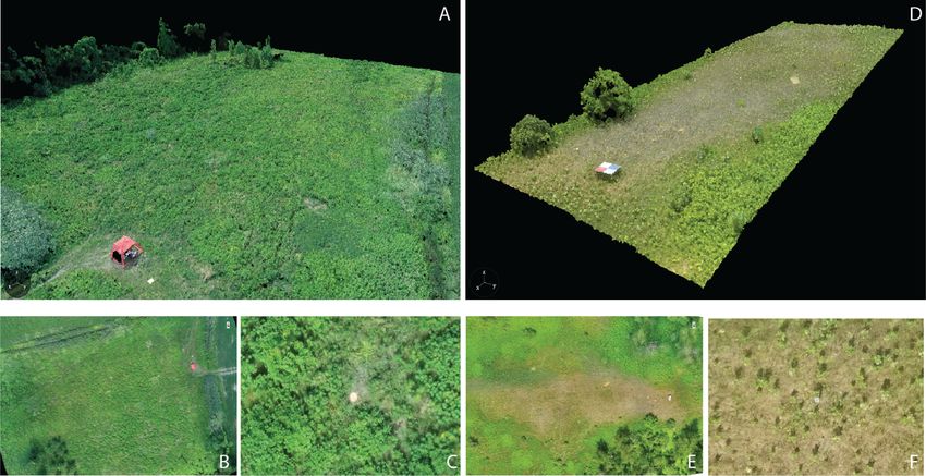
Drones 2020, 4, 13                                                                                   2 of 26

up to ~100 hectares [1,27,28]. In addition, more operationally demanding systems such as hyperspectral
pushbroom sensors [22,29], thermal imagers [24] and LiDAR [30] are being implemented on UASs,
providing new insights for data fusion and advanced data analysis [31]. Centimeter level accuracies
are particularly important in these multi-sensor applications where spatial alignment of the different
datasets is needed. At the moment, the vast majority of applications within the public-domain, are
limited to small UASs with limited coverage due to the near-universal regulatory requirement that these
systems be flown within visual-line-of-sight (VLOS) [32]. As well, limited battery performance [33]
and a restricted envelop of weather conditions for operations compounds the current limitations of
small UAS operations. However, as UAS technology matures and more robust operations such as
beyond-visual-line-of-sight (BVLOS) become common [34], novel applications will continue to be
tested [35]. It is important to recognize, however, that small UAS BVLOS is still in its early stages of
development [36] and it will be some time before unfettered BVLOS operations will be allowed by
airspace regulators. In these future BVLOS applications, using GCPs collected on-site will not always
be a viable option because of the large extents that will be covered by the imagery and the potential
remoteness or inaccessibility of the study area (e.g., [35,37]).
       While the early development of SfM photogrammetry emerged approximately 40 years ago [38],
its popularity in geomatics has increased with access to higher performance computers/workstations
and the availability of UAS-based photography [39]. A generic SfM pipeline reconstructs the landscape
as a sparse 3D point cloud from overlapping 2D photographs. Additional products such as a
dense 3D point cloud (through the application of an MVS algorithm), a DSM from interpolation
of the point cloud or a textured mesh can also be generated. The SfM algorithms locate common
points in the multiple 2D photographs taken from different viewing positions (and angles) from
which the landscape is reconstructed in 3D [40,41]. The SfM pipeline does not actually require any
geopositioned information for the photographs. In the absence of coordinates, it recovers the camera
parameters, and position and orientation estimates from the photographs resulting in more flexibility
than conventional photogrammetry from stereo-pairs [42]. A review of different algorithms and
implementations of SfM can be found in [43].
       Many factors that affect the quality of the UAS-based SfM-MVS photogrammetry products (e.g.,
orthomosaic and DSM) are described in detail by [44,45]. The first consideration is the image size
as defined by the number of pixels on the imaging sensor, namely the pixel size and pixel pitch (i.e.,
the linear distance from the center of a pixel to the center of the adjacent pixel on the detector array).
The size of the detector array and the size of the pixels affect the resolving power of the sensor. Given a
specific pixel size, larger arrays accommodate more pixels that capture more incoming electrons, but
given a specific sensor size, larger pixels are a tradeoff in a corresponding loss of spatial resolution.
The second factor is the sensor’s radiometric resolution (e.g., 8–14 bits), where a higher radiometric
resolution corresponds to the system being able to accommodate a greater range of intensities of
incoming radiation. A final important factor to consider is the accurate location of imaged features with
respect to the real-world coordinates (absolute position) and accurate geometries (dimensions, distances
and volumes) as they are represented in the products (relative accuracy). In addition, minimization of
image blur and distortion for a given camera and lens implementation during mission planning requires
the consideration of specific camera and lens parameters (e.g., f-stop, shutter speed and ISO) [44].
In addition to hardware specifics, several studies have addressed equally important aspects of data
collection from UASs such as flight altitude [46,47], image overlap [48] and environmental conditions
(i.e., wind speed) for optimizing data collection [22], which are closely related to the implementation’s
objective(s).
       However, positional accuracy is still a very challenging attribute to conceive and quantify for
many UAS practitioners. The general lack of knowledge of true positional errors is in part, due to
the relatively high degree of ease of collecting ultra-high-resolution (few cm) images. It has been
recognized, previously, that UASs and their system implementation requires improvement [49,50].
Applications where high accuracy and/or precision (e.g., repeatability) are required, have relied on the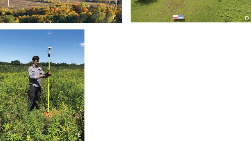
Drones 2020, 4, 13                                                                                  3 of 26

use of ground control points (GCPs) for improving product geolocation with respect to real-world
coordinates and for ensuring accurate measurements of geometries within the end-products (e.g., [51]).
For instance, [52–54] have shown the utility of GCPs for improving horizontal and vertical positional
accuracy for different data acquisition scenarios (e.g., GCP density and distribution). Nevertheless, as
stated by [55], implementing a GCP network can be impractical in certain situations, for example, glacial
terrains and fluvial systems [11] or with BVLOS flights. Similar situations where GCPs are logistically
unfeasible or dangerous are volcanic crater mapping, post-fire landscape (before fully cooled), fragile
ecosystems (e.g., peatlands), marine studies, glacier/snowpack and animal counts/population studies.
      Given a stable platform and the implementation of a gimbal and inertial measurement unit (e.g.,
attitude) to record the position and orientation of photographs, the positional accuracy of UAS derived
photogrammetry products that do not use GPCs is largely determined by the type, frequency(ies) and
number of global navigation satellite systems (GNSS) constellations used for navigation purposes
and geotagging. Moreover, the accuracy obtained is influenced by the type of data processing option,
which ranges from basic onboard position calculation to more advanced post-processing kinematic
(PPK) or real-time kinematic (RTK) solutions (Figure 1). Here, we provide a brief description from
low-cost onboard position acquisition, to PPK and RTK solutions. Onboard low-cost GNSS systems
(Figure 1A), for example, generally use single-frequency receivers (L1 and/or F1), which are sufficient
for navigation but the accuracy of positioning remains metric (1–3 m) [56,57]. Although less common,
dual-frequency GNSS receivers (L1/L2 and/or F1/F2) provide a faster position lock with higher accuracy
and precision [58] but not necessarily enough for applications where cm level accuracy is required [22].
Post-processing kinematic (Figure 1B) solutions rely on a high precision and accurate GNSS base station
that can be a local receiver or a commercial service provider. The fixed location of the base station is
used to compute the geotags after data acquisition. The PPK solution can also use precise clock and
ephemeris data in post-processing, providing consistent and repeatable positions with an accuracy of
several centimeters [59]. In addition to a precisely located base station, RTK solutions (Figure 1C) also
rely on a stable radio, cellular or Wi-Fi link between the base station and the GNSS receiver to geotag
the photographs with an accurate location in real-time. For example, based on a single frequency RTK
module, [60] a horizontal accuracy of 1.5 cm and a vertical accuracy of 2.3 cm was obtained.
      The purpose of this study is to evaluate the positional and within-model relative accuracies of
SfM and SfM-MVS photogrammetry reconstructions of low relief landscapes without the inclusion of
GCPs for a range of multirotor VTOL (vertical takeoff and landing) UAS with camera systems from
various price points (US$1000 to >US$50,000). We follow the American Society for Photogrammetry
and Remote Sensing 2015 [61] definitions of absolute accuracy as “a measure that accounts for all
systematic and random errors in a data set”; positional accuracy as “the accuracy of the position of
features, including horizontal and vertical positions, with respect to horizontal and vertical datums”;
and relative accuracy as “a measure of variation in point-to-point accuracy in a data set”. We further
refer to positional error as “the difference between data set coordinate values and coordinate values
from an independent source of higher accuracy for identical points”.
      Overall, the following study used 14 distinct UASs wherein, there was one high-cost enterprise
UAS manufactured by Aeyron Labs and the remaining 13 were all manufactured by DJI (Dà-Jiāng
Innovations). Our decision to focus mainly on these systems stems from four factors which are:
(1) airframe market share, (2) range of performances, (3) flight controller supply market, and (4) access.
First, as of 2019, DJI accounted for approximately 76.8% of the market in the USA (based on FAA
registrations) [62]. In Canada, in the first quarter of 2020, 30 of 241 UAS models with manufacturer
assurance declarations submitted to Transport Canada for advanced operations were DJI systems.
An additional 23 UASs on the Transport Canada list were from manufacturers that modified various
DJI UASs [63]. Second, the UAS from our study covers a range of grades from consumer (mass market)
to professional and enterprise systems, which are accessible to most users. Third, many custom-built
systems or third-party manufactured systems’ flight controllers are frequently purchased from DJI.
On the Transport Canada list, a minimum of 15 additional UASs were listed with safety declarations in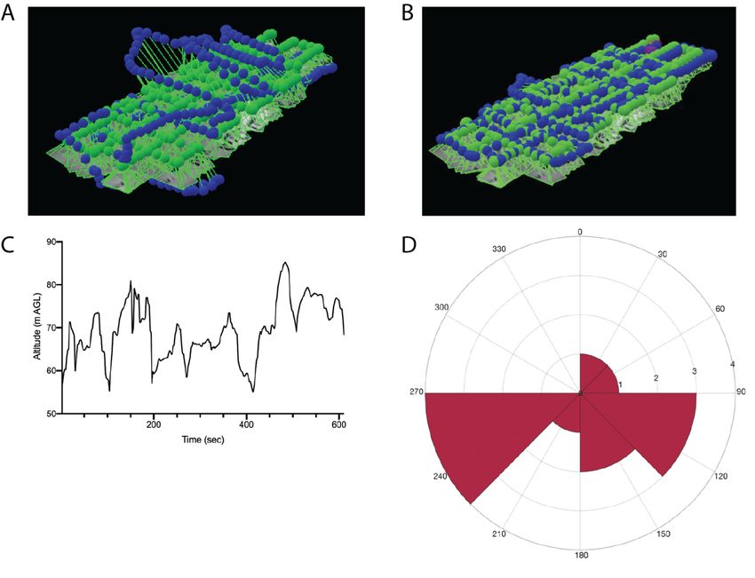
115 position lock with higher accuracy and precision [58] but not necessarily enough for applications
116 where cm level accuracy is required [22]. Post-processing kinematic (Figure 1B) solutions rely on a
117 high precision and accurate GNSS base station that can be a local receiver or a commercial service
118 provider. The fixed location of the base station is used to compute the geotags after data acquisition.
119 The PPK
Drones solution
2020, 4, 13 can also use precise clock and ephemeris data in post-processing, providing 4 of 26
120 consistent and repeatable positions with an accuracy of several centimeters [59]. In addition to a
121 precisely located base station, RTK solutions (Figure 1C) also rely on a stable radio, cellular or Wi-Fi
122 configurations
link between the using thestation
base DJI flight
andcontrollers
the GNSS(e.g., A3, A3
receiver Pro andthe
to geotag N3). By evaluating
photographs these
with systems,
an accurate
123 our study provides a large number of entities (e.g., service providers and individuals),
location in real-time. For example, based on a single frequency RTK module, [60] a horizontal who use
124 commercial
accuracy of off-the-shelf
1.5 cm and aUASs, anaccuracy
vertical assessment of the
of 2.3 cm accuracy of the systems for the scenario we cover
was obtained.
125 in this study. Lastly, the UASs tested here are the systems we had access to over the course of the study.
126
127 Figure 1.
Figure 1. Three
Three common
common configurations
configurations for
for geotagging
geotagging photographs
photographs for
for aa SfM
SfM ororSfM-MVS
SfM-MVSworkflow.
workflow.
128 A) Onboard
(A) position calculation:
Onboard position calculation:positions
positionsofofthe
thephotographs
photographs areare based
based on onthethe location
location of UAS
of the the UAS
and
129 and recorded
recorded in thein the(B)
Exif; Exif; B) post-processing
post-processing kinematic kinematic (PPK): positions
(PPK): positions of the photographs
of the photographs are computed are
130 computed after the flight from the rover and base station logs. A commercial or local base
after the flight from the rover and base station logs. A commercial or local base station can be used; station can
(C) real-time kinematic (RTK): positions of the photographs are computed in real-time with corrections
sent to the rover directly from the base station. The base station can be local or in specialized scenarios,
a commercial base station correction can be sent via NTRIP to the remote controller. The accuracy of
the photograph positions for both the PPK and RTK solutions greatly depends on the accuracy of the
base station location.
2. Materials and Methods
2.1. Study Sites
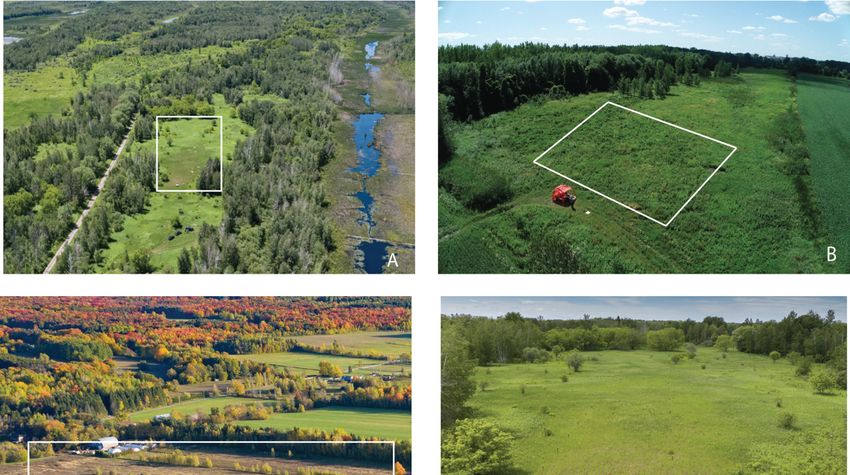
This study was carried out over a three-year period at three mid-latitude sites in Eastern Canada
(shown in Figure 2): (1) a 2.8 ha field of herbaceous vegetation next to the Mer Bleue peatland (MB),
near Ottawa, Ontario (Figure 2A); (2) an abandoned 3.7 ha agricultural field on île Grosbois (IGB),
near Montreal, Quebec (Figure 2B); (3) a 1.5 ha agricultural field in Rigaud, Quebec (Figure 2C). As a
means to introduce checkpoints to validate the horizontal and vertical accuracies of the SfM and
SfM-MVS products, 70 cm tall wooden posts were placed in the field at MB. Each post had a 10 cm
wide metal plate affixed to the top. The plates were painted matte grey and marked with an “X” in the
center using contrasting (black and white) tape. These posts were installed for multi-year use at the
site (Figure 2D). At the two other sites, checkpoints consisted of circular plastic orange bucket lids
(30.5 cm diameter and 23.5 cm diameter) marked with an “X” in contrasting tape that were placed
flat on the ground randomly before each flight (Figure 2E). All three study sites have relatively low
topographic variability comprised of the variable herbaceous vegetation height at MB and IGB and the
soil separating the furrows in the plowed field (Rigaud). For all flights, the weather was sunny with
few clouds and little wind.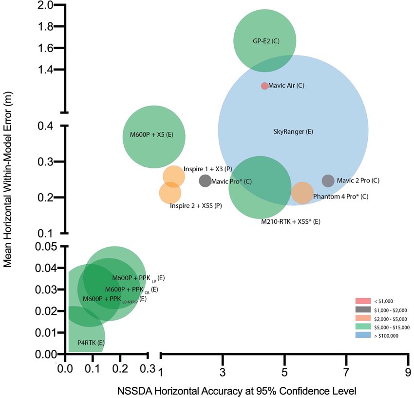
Drones 2020, 4, 13 5 of 26
Drones 2020, 4, x FOR PEER REVIEW 5 of 27
179
180 Figure 2. Aerial
Figure viewview
2. Aerial of theofthree studystudy
the three sites. sites.
A) Herbaceous field next
(A) Herbaceous tonext
field the Mer Bleue
to the Mer(MB)
Bleuepeatland,
(MB) peatland,
181 Ontario; B) abandoned agricultural field on île Grosbois (IGB), Quebec; C) agricultural
Ontario; (B) abandoned agricultural field on île Grosbois (IGB), Quebec; (C) agricultural field infield
fallow
in fallow
182 in Rigaud, Quebec. The white boxes indicate the location of the fields within the
in Rigaud, Quebec. The white boxes indicate the location of the fields within the landscape; landscape; D) posts
(D) posts
183 in the
in MB fieldfield
the MB with metal
with metaltargets affixed
targets to to
affixed the
thetop;
top;E)(E)
temporary
temporarytarget
targetused
usedininIGB
IGBand
and Rigaud
Rigaud being
184 being measured with a Trimble Catalyst GNSS
measured with a Trimble Catalyst GNSS receiver. receiver.
185 2.2. 2.2.
UASs and Camera
UASs Systems
and Camera Tested
Systems Tested
186 We We
tested fourteen
tested UASs
fourteen ranging
UASs in weight
ranging fromfrom
in weight 430 g430
to 14
g tokg14(Table 1 and1Table
kg (Tables and 2).2). Flights were
187 wereconducted
conducted at at 30–45
30–45 mm above
above ground
ground level
level (AGL)
(AGL) nominally,
nominally, with with orthogonal
orthogonal flight
flight lines.
lines. TheThePhantom
188 Phantom
4 RTK4(P4RTK),
RTK (P4RTK), the Matrice
the Matrice 600 Pro600
RTKPro(M600P),
RTK (M600P), and Matrice
and Matrice 210-RTK 210-RTK
(M210-RTK)(M210-RTK)
required an
189 required an external
external base to
base station station to function
function in RTK in RTKmode.
flight flight mode.
Flight Flight line spacing
line spacing and camera
and camera triggering
190 triggering were optimized
were optimized forsystem
for each each system
by thebyflight
the flight controller
controller software
software whilewhile maintaining
maintaining 80%80% frontlap
191 frontlap and sidelap
and sidelap coverage.
coverage. Photographs
Photographs werewere collected
collected at nadir
at nadir withwith
thethe exception
exception of of
thethe Mavic
Mavic Air for
192 Air which
for which the maximum allowable angle by the flight controller software was –80°.
◦
the maximum allowable angle by the flight controller software was –80 . All onboard cameras All onboard
193 cameras were triggered directly by the UAS. Shutter speed, ISO, aperture and exposure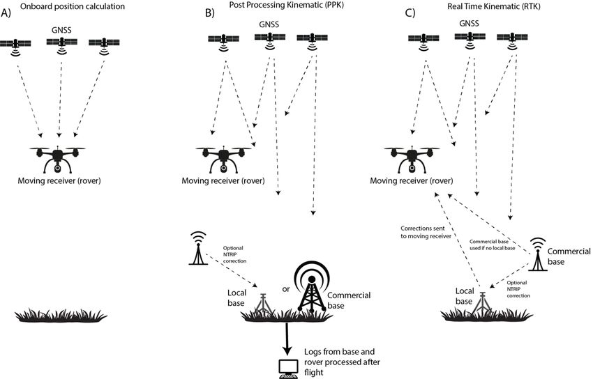
Drones 2020, 4, 13                                                                             6 of 26

were triggered directly by the UAS. Shutter speed, ISO, aperture and exposure compensation were
automatically set by the on-board cameras without user intervention. The onboard cameras were also
set to autofocus mode.
      For the M600, the digital single-lens reflex (DSLR) camera was mounted on a Ronin MX gimbal
(DJI, Shenzhen China) for stabilization and orientation. Two configurations were evaluated: (1) PPK
mode where geotagging was achieved via an M+ RTK GNSS module (Emlid, St Petersburg, Russia) to
record the position and altitude and a PocketWizard MultiMax II intervalometer (LPA Design, South
Burlington, VT, USA) to trigger the camera at 2-second intervals; (2) in stand-alone mode, the DSLR
was also triggered by the intervalometer but geotagging was automated with a Canon GP-E2 GPS
receiver connected to the DLSR’s hot shoe. In all cases, the DLSR was operated in “programmed auto”
mode, in which the aperture and shutter speed are automatically set by the camera but the user has
control of the ISO and exposure compensation. The ISO was set to 800 with no exposure compensation.
The lens was set to autofocus, using all of the available points of the camera’s autofocus sensor.
      The P4RTK received RTK corrections from the Can-Net CORS network via a virtual reference
station (VRS) mountpoint utilizing both GPS and GLONASS constellations. All P4RTK photographs
were captured in the fixed status for maximum geolocation accuracy. Three types of geotagging
were implemented for the M600P DSLR photographs collected in PPK mode. First, with the “local
base” configuration (PPKLB ) a base station dedicated to collecting GNSS data for the photographs
was set up. For this, we used an RS+ single-band receiver (Emlid, St Petersburg, Russia). Second,
for the local base configuration with the added NTRIP correction (Networked Transport of Radio
Technical Commission for Maritime Services (RTCM) via Internet Protocol), PPKLB-NTRIP , the RS+
base station received the incoming corrections from the SmartNet North America NTRIP casting
service on an RTCM3-iMAX (individualized master-auxiliary) mount point utilizing both GPS and
GLONASS constellations. These corrections were transmitted to the M+ receiver onboard over LoRA
(long-range) 915 MHz radio. Lastly, for the PPK configuration with a commercial base station, PPKCB ,
the SmartNet North America station in Vaudreuil-Dorion (Station QCVD—16 km baseline) was used
in post-processing.
      All photographs (from all UASs) were acquired as jpgs except for the DSLR, which acquired
photographs in Canon RAW (.CR2) format. These were subsequently converted to large jpg in Adobe
Lightroom® with minimal compression for analysis.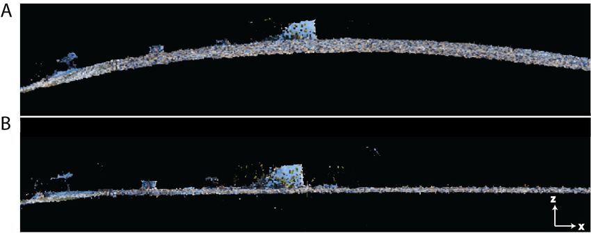
Drones 2020, 4, 13                                                                                                                                                                              7 of 26

      Table 1. List of UASs tested ordered by takeoff weight. * These systems only utilize RTK for the flight controller and the geotagging only uses GPS L1 and GLONASS
      F1 frequencies. The DSLR camera used was a Canon 5D Mark III.

                                                     Takeoff           Study                     Cost Category ($US)      Altitude                                       Flight Controller
                             UAS                                                 Geotagging                                                       GNSS
                                                    Weight (kg)         Site                     at Time of Purchase      AGL (m)                                            Software
                         DJI Mavic Air                  0.430           IGB       Onboard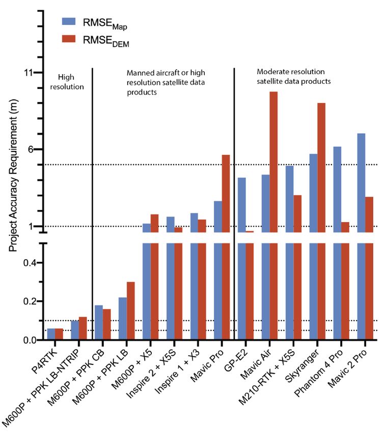
Canon 5D Mark III FF 36 x 24 mm 22.1 5760 x 3840 6.25 84
CMOS sensor
236 *Based on the sensor size stated by Sony the calculated pixel size is 1.2 μm but for this camera, Pix4D considers
237 the usable
Drones 2020, area
4, 13 on the sensor rather than the physical dimension (Pix4D, pers. comm). Rolling shutter distortion
8 of 26
238 for all CMOS sensors was estimated and mitigated through Pix4D [64].
239
240 Figure 3.
Figure 3. Illustration
Illustration of
of the
therelative
relativedifferences
differencesininsensor
sensorsize
size
ofof the
the cameras
cameras used
used in in
thisthis study
study (Table
(Table 2).
241 2).
2.3. Photograph Geotagging
242 2.3. Photograph Geotagging
The non-RTK/PPK systems automatically geotag the acquired photographs with the horizontal
243 and vertical position of the
The non-RTK/PPK UAS time-synchronized
systems automatically geotag to thetheonboard
acquiredGNSS receiver (and
photographs camera
with attitude)
the horizontal
244 with
and vertical position of the UAS time-synchronized to the onboard GNSS receiver (and altitude
the exception of the Mavic Air that writes the horizontal position to the Exif data, but for camera
245 only records
attitude) withthethe
barometer
exception measurement
of the Mavic(height
Air thatabove
writesthethe
take off point).position
horizontal Therefore, for the
to the ExifMavic
data, Air,
but
246 elevation
for altitude(HAE)
only was manually
records calculated
the barometer based on the(height
measurement flight altitude
above the and theoff
take elevation
point). of the take-off
Therefore, for
247 point and added to the Exif. The P4RTK automatically geotagged photographs with
the Mavic Air, elevation (HAE) was manually calculated based on the flight altitude and the elevation the incoming RTK
248 corrections applied.
of the take-off pointForandalladded
UASs,to inthe
addition to the
Exif. The geotagged
P4RTK position, the
automatically camera roll,
geotagged pitch and with
photographs yaw
249 at
thethe time of RTK
incoming framecorrections
acquisitionapplied.
was also written
For intointhe
all UASs, Exif. to the geotagged position, the camera
addition
250 For the
roll, pitch andDSLR
yaw at photographs with positions
the time of frame acquisitiondetermined
was also writtenvia PPKinto , PPK
CBthe LB and PPKLB-NTRIP ,
Exif.
251 the horizontal
For the DSLR coordinates and altitude
photographs needed todetermined
with positions be calculated in PPK
via post-processing.
CB, PPKLB and The
PPK open-source
LB-NTRIP, the
252 RTKLib software [65] was used to calculate the geotag of each DSLR photograph.
horizontal coordinates and altitude needed to be calculated in post-processing. The open-source For the PPK LB-NTRIP
253 configuration,
RTKLib software the[65]
geotags
was usedwereto calculated
calculate thewith andofwithout
geotag each DSLRprecise clock andFor
photograph. ephemeris data
the PPKLB-NTRIP
254 downloaded
configuration,from the the Natural
geotags Resources
were Canada’s
calculated with Canadian
and without Geodetic
preciseSurvey.
clock For
andeach of the DSLR
ephemeris data
255 PPK configurations, a lever arm correction was also applied. The precise
downloaded from the Natural Resources Canada’s Canadian Geodetic Survey. For each of the DSLRDSLR attitude on the Ronin
MX at the time of frame acquisition is not recorded.
For the photographs geotagged with the onboard GNSS receivers (no RTK or PPK correction),
the altitude tags were discarded due to the large errors recorded in the Exif data by each system (>10 m
in some cases). The altitude tags were manually recalculated from the barometer measurements of
altitude above the take off point (m ASL or HAE) added to the known ground elevation. The accuracy
of the barometer measurements had previously been assessed to be ±10 cm [22]. Because the GP-E2
does not have a barometer the correct altitude was determined from the flight logs and a lever arm
correction. For the P4RTK the lever arm correction is automatically taken into account in the positions
recorded in the Exif.
2.4. Checkpoint Position Measurement
The targets used as checkpoints were measured after every flight. On August 15, 2019, ten
checkpoints were measured using a Trimble Catalyst GNSS/RTK receiver with corrections obtained
using the Can-Net VRS network. Only points with a fixed status were considered in the analyses.
At MB and Rigaud, the RS+ with incoming corrections from the SmartNet North America NTRIP
service was used after all flights (fifteen checkpoints). The accuracy of the RS+ with the incoming
NTRIP correction was previously verified in comparison to the location of the Natural Resources
Canada High Precision 3D Geodetic Passive Control Network station 95K0003 in Dorval, Quebec.
The error in the computed position of the station by the RS+ was determined to be 0.6 cm (X), 2.7 cm (Y)
and 5.1 cm (Z). For the Trimble Catalyst, the accuracy was assessed to be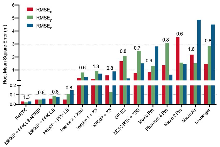
Drones 2020, 4, 13 9 of 26
Drones 2020, 4, 13                                                                                 10 of 26

2.6. Model Accuracy Assessment
     Horizontal (x and y) and vertical (z) positional accuracies were determined for the SfM models
from the coordinates of the checkpoints within Pix4D (Figure 4). From the reported values of RMSEx
and RMSEy , the horizontal linear RMSE in the radial direction (includes both x- and y-coordinate
errors, RMSEr ) and National Standard for Spatial Data Accuracy (NSSDA) horizontal accuracy at
a 95% confidence level were computed according to Equations 1 and 2 following [61]. Because the
vertical error in vegetated terrain (z-component) typically does not follow a normal distribution,
the vegetated vertical accuracy (VVA) at the 95th percentile is calculated following [61] (and discussed
rather than RMSEz ).                           q
                                     RMSEr =      RMSE2x + RMSE2y                                      (1)

                     Horizontal accuracy at 95% con f idence level = 1.7308 × RMSEr                    (2)

where RMSEx is the horizontal linear RMSE in the easting and RMSEy is the horizontal linear RMSE in
the northing. In the computation of RMSEx and RMSEy the NSSDA assumes that the errors are random
errors that follow a normal distribution. We computed the D’Agostino–Pearson omnibus k2 test for
normality on ∆x and ∆y. This tests against the alternatives of skewed and/or kurtic distributions.
Due to the smaller than recommended sample size for checkpoints [61], the significance of RMSEr and
the VVA at the 95th percentile should be treated with caution.
     The within-model horizontal accuracy was determined by comparing the distances between all
pairs of checkpoints from the orthomosaic and from the field measured coordinates. The locations of
the targets in the orthomosaics were manually located, and the coordinates extracted with ArcMap 10.7.
For the distance calculations between pairs of checkpoints, we took into consideration standard error
propagation of the uncertainty in the coordinates of the checkpoints as determined on the ground, as
well as user uncertainty locating the exact center of checkpoints in the orthomosaics. User uncertainty
in digitization was estimated at a maximum of 2 pixels in x and y. For the uncertainties in the ground
GPS measurements, the values described in Section 2.3 were used. The error propagation to determine
the uncertainty in the distance measurements was done by calculating the partial derivatives of the
distance between two points with respect to both the x and y coordinates, multiplication with the
uncertainty of those two variables, and addition of those terms in quadrature (Equations 3 and 4).

                                              D = f xi , x j                                           (3)
                                         s
                                                         !2                   !2
                                             ∂D                 ∂D
                                  δD =           × ∂xi        +      × ∂x j                            (4)
                                             ∂xi                ∂x j
where D is the distance between the location of the two checkpoints (xi and xj ) and δD is the uncertainty
in the distance calculation.

2.7. Camera Focal Length Considerations for the Phantom 4 RTK
     For the P4RTK, we initially followed Pix4D’s recommended workflow [72], which included
applying the built-in optimized camera parameters. For greatest accuracy, all photograph and
checkpoint coordinates were first converted to UTM (zone 18N) coordinates and ellipsoidal heights with
NAD83(CSRS) 2010 epoch as the reference frame, using Natural Resources Canada’s TRX software [73].
The same reference frame was used for the outputs. The TRX software also allows the user to set the
GPS epoch correctly (i.e., provinces adopted different epochs, see [74]).
     Initial results for the P4RTK using this recommended workflow yielded low RMSEx, RMSEy ,
RMSEr (2–4 cm), but an 18 cm RMSEz (Table 3, Figure 5). Setting the initial camera parameters from
“All” to “All prior”, as recommended by Pix4D, actually made results worse (Table 3, second row).
The “All prior” setting forces the optimal internal parameters (focal length, coordinates of principal
point, radial distortion parameters and tangential distortion parameters), to be close to the initial
Drones 2020, 4, 13 11 of 26
values from the camera database. In contrast, “All” optimizes these parameters starting from the
initial values in the database with subsequent recalculation. The values are recalculated based on
the calibrated photographs in the dataset [68]. We manually decreased the focal length parameter in
the camera description by 0.01 mm increments, keeping the “All prior” setting to fix the new focal
length. The lowest RMSEz (1.4 cm; Table 3, Figure 5) was obtained by reducing the default focal length
from 8.58 mm to 8.53 mm, after which the vertical accuracy gradually worsened (Table 3, Figure 5).
Horizontal accuracy (RMSEx, RMSEy and RMSEr ) was largely unaffected by the focal length. We used
the optimized camera parameters from the best model for all other analyses, using the “All prior”
initial camera parameter calibration setting.
Table 3. Effects of changing the camera focal length parameter on location accuracy for the Phantom
Drones 2020, 4, x FOR PEER REVIEW 12 of 27
4 RTK. The best model is highlighted in bold. FL: focal length. * Generalized FL of the P4RTK camera
in Pix4D.
4 All prior 8.55976 8.557 0.028982 0.023446 0.037 0.150739
Initial FL Optimized FL RMSEx RMSEy RMSEr RMSEz
Trial 5 Calibration
All prior 8.54976 8.547 0.02891 0.023342 0.037 0.100179
(mm) (mm) (m) (m) (m) (m)
1 6 All All prior 8.53976
8.57976 * 8.538
8.494 0.028852 0.022756 0.037 0.037 0.050315
0.028558 0.023239 0.182723
2 All prior 8.57976 * 8.576 0.029126 0.023656 0.038 0.251885
7 All prior 8.52976 8.528 0.028788 0.023137 0.037 0.0144
3 All prior 8.56976 8.567 0.029048 0.023551 0.037 0.201478
4 8 All prior
All prior 8.55976
8.51976 8.557
8.518 0.028982 0.023037
0.028724 0.023446 0.037 0.037 0.150739
0.055332
5 All prior 8.54976 8.547 0.02891 0.023342 0.037 0.100179
6 9 All prior
All prior 8.50976
8.53976 8.509
8.538 0.028661
0.028852 0.022939
0.023239 0.037 0.037 0.105318
0.050315
7 All prior 8.52976 8.528 0.028788 0.023137 0.037 0.0144
10 All prior 8.49976 8.499 0.028598 0.02284 0.037 0.15587
8 All prior 8.51976 8.518 0.028724 0.023037 0.037 0.055332
9 11 All prior
All prior 8.50976
8.48976 8.509
8.489 0.028661 0.022743
0.028536 0.022939 0.036 0.037 0.206690.105318
10 All prior 8.49976 8.499 0.028598 0.02284 0.037 0.15587
353 11 All prior 8.48976 8.489 0.028536 0.022743 0.036 0.20669
354
355 Figure5.5. Relationship
Figure Relationship between
between focal
focal length
length (FL)
(FL) (mm)
(mm)andandRMSE(
RMSE(r,z ) for the P4RTK. The effect on
r,z) for the P4RTK. The effect on
356 RMSE
RMSEzzof
ofusing
usingthe
thegeneralized
generalizedPix4D
Pix4Dfocal
focallength
length(8.57976
(8.57976mm)
mm)for
forthe
theP4RTK
P4RTKandandgeneralized
generalizedfocal
focal
357 length
length with “All Prior” initial camera parameters are shown by the circle and trianglerespectively.
with “All Prior” initial camera parameters are shown by the circle and triangle respectively.
3. Results
358 3. Results
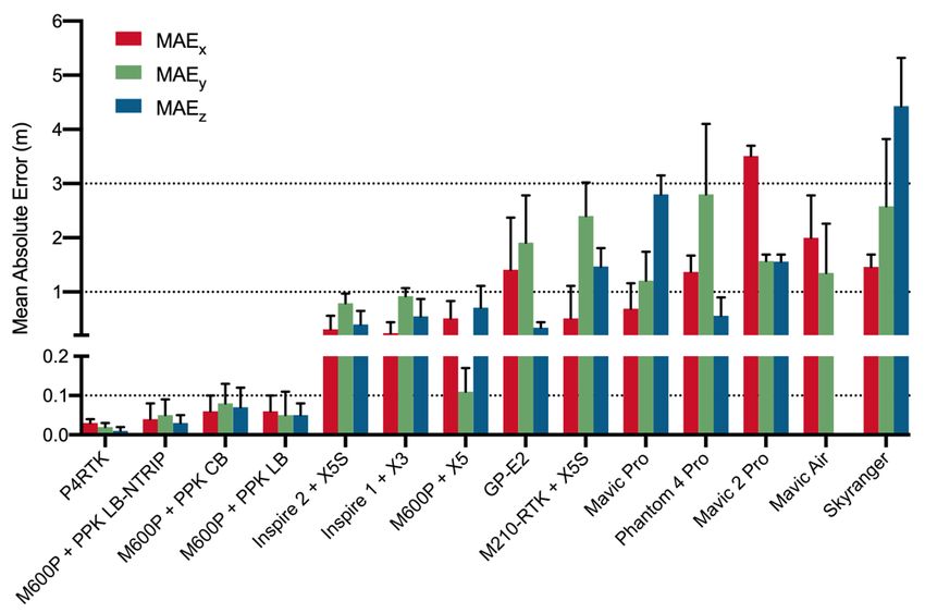
Summary statistics comprised of the RMSE(x,y,z,r) and mean absolute error (MAEx,y,z ) are shown
359 Summary
in Figures 6–8 tostatistics
illustratecomprised
∆x, ∆y andof ∆z
thebetween
RMSE(x,y,z,r)
the andSfM mean
modelabsolute
derivederror (MAEx,y,z
checkpoint ) are shown
locations and
360 in Figures 6–8 to illustrate Δx, Δy and Δz between the SfM model derived checkpoint locations
those measured in situ. Both MAE and RMSE measure the average magnitude of the positional errors, and
361 those measured
however, the RMSE in situ. Both sensitive
is more MAE andto RMSE
largemeasure the average
errors (outliers). Formagnitude ofand
this reason, the positional
because RMSEerrors,
z
362 however, the RMSE is more sensitive to large errors (outliers). For this reason, and because RMSEz is
363 not expected to follow a normal distribution in vegetated terrain, the VVA at the 95th percentile
364 (Figure 8) is examined to quantify the positional accuracy in elevation.
365Drones 2020, 4, 13 12 of 26
Drones 2020, 4, x FOR PEER REVIEW 13 of 27
is not expected to follow a normal distribution in vegetated terrain, the VVA at the 95th percentile
(Figure 8) is
Drones 2020, 4, xexamined to quantify the positional accuracy in elevation.
FOR PEER REVIEW 13 of 27
366
367 Figure 6. RMSEx,y,z (positional accuracy) for the SfM sparse point clouds. The number above each
368
366 group of bars is the GSD in cm.
367
369 6. RMSEx,y,z
Figure 6.
Figure (positional accuracy)
x,y,z (positional accuracy) for
for the
the SfM
SfM sparse point clouds. The
The number above each
368 group of bars is the GSD in
group of bars is the GSD in cm. cm.
369
370
371 7. Positional error (as
Figure 7. (as MAE x,y,z)) for
MAEx,y,z for the SfM sparse point clouds.
clouds. The standard deviation of
372
370 MAE is also shown (in m).
371 Figure 7. Positional error (as MAEx,y,z) for the SfM sparse point clouds. The standard deviation of
372 MAE is also shown (in m).Drones 2020, 4, 13 13 of 26
Drones 2020, 4, x FOR PEER REVIEW 14 of 27
373
374 Figure
Figure 8. RMSE
8. RMSE r horizontal
r horizontal accuracy
accuracy at the
at the 95th95confidence
th confidence level and vegetated vertical accuracy
level and vegetated vertical accuracy (VVA)
375 at (VVA) at percentile
the 95th the 95 percentile
th for the
for the SfM SfM sparse
sparse point cloud.
point cloud.
376 AsAs expected,the
expected, theUAS
UASwith
with RTK
RTK or or PPK
PPK geotagged
geotagged photographs
photographsproduced
producedmodelsmodels with thethe
with
377 lowest
lowest positionalerrors
positional errors (RMSE,
(RMSE, MAE MAEand andVVA).
VVA).These
Thesewere alsoalso
were the the
mostmost
accurate systems
accurate for thefor
systems
378 thewithin-model
within-model measurements
measurements of of
distances
distances between
betweencheckpoints
checkpoints (Figure 9). 9).
(Figure TheTheP4RTK,
P4RTK, a system
a system
379 specifically
specifically designed
designed for enterprise
for enterprise SfM-MVS
SfM-MVS photogrammetry,
photogrammetry, includesincludes an incoming
an incoming NTRIP
NTRIP correction
380 to correction to its base
its base station and station
directlyand directly
applies RTKapplies RTK corrections
corrections to the of
to the geotags geotags of the photographs.
the photographs. Both the
381 Both the positional error (RMSE r: 4 cm, MAEz: 1 cm, VVA: 3 cm) and within-model error (μ = 0.8 ± 2
positional error (RMSEr : 4 cm, MAEz : 1 cm, VVA: 3 cm) and within-model error (µ = 0.8 ± 2 cm) of
382 cm)
this of thisare
system system are analogous
analogous to the low to errors
the low errors achieved
achieved by various by various
UASs asUASs as reported
reported in the
in the literature
383 literature with GCPs included in the processing (see summary by [59]) (Figure 10A–C). It is also the
with GCPs included in the processing (see summary by [59]) (Figure 10A–C). It is also the system
384 system with the highest percentage (84%) of within-model distance calculation errors that were less
with the highest percentage (84%) of within-model distance calculation errors that were less than the
385 than the uncertainty of the measurements (Figure 9). In order to achieve the high vertical accuracy,
uncertainty of the measurements (Figure 9). In order to achieve the high vertical accuracy, an important
386 an important consideration for the P4RTK is the calculation of the specific focal length of the lens
consideration for the P4RTK is the calculation of the specific focal length of the lens unique to the
387 unique to the system being used (Table 3, Figure 5). The generalized camera model focal length within
388 system being used (Table 3, Figure 5). The generalized camera model focal length within Pix4D
Pix4D (8.58 mm) resulted in unreasonably high vertical errors (18–25 cm) for our particular camera.
389 (8.58
It ismm) resulted
possible in unreasonably
that other high vertical
users with camera errorscloser
focal lengths (18–25to cm) for ourPix4D
the default particular
valuescamera.
could getIt is
390 possible that other users with camera
high vertical accuracies out of the box. focal lengths closer to the default Pix4D values could get high
vertical accuracies out of the box.
The UAS with the second-lowest positional and within-model errors (M600P + PPKLB-NTRIP)
overcomes the lack of onboard generated geotags through third-party hardware and software resulting
in a 7 cm RMSEr, 3 cm MAEz, 10 cm VVA and low within model error (µ = 3 +/− 4 cm) (Figures 6–9).
While this system had a low percentage of within model distance errors less than the uncertainty of the
measurements (9%), the errors were close to the uncertainty estimates (Figure 9). The same system
performed slightly worse (higher error) with PPKCB and PPKLB (Figures 6–8). Negligible differences
were seen by using the fast versus precise clock and ephemeris data (PPKLB-NTRIP).
The remaining systems relying on onboard GNSS geotagging resulted in positional errors ranging
from an average RMSEr of 0.60 m (M600P + X5S) to >3 m (SkyRanger, Mavic 2 Pro and Phantom
4 Pro) (Figures 6–8). It is important to note that for the three UASs with RMSEr > 3 m, there is a
substantial difference in RMSEx vs RMSEy (and MAEx versus MAEy ) (Figures 6 and 7) resulting in the
larger values of RMSEr . For operational use without GCPs for these UASs, results suggest further
investigation would be warranted to determine, if possible, the reason for the larger error in oneDrones 2020, 4, x FOR PEER REVIEW 15 of 27
Drones 2020, 4, 13 14 of 26
direction. Overall, the non-RTK/PPK systems were consistent in the within-model horizontal distance
measurement errors (µ = 0.21–0.26 m) except for the SkyRanger (µ = 0.39 +/− 0.28 m) and Mavic Air
(µ= 1.2 +/− 0.48 m) (Figure 9). All non-RTK/PPK systems have a lower within-model distance error
compared to4,the
Drones 2020, positional
x FOR error (RMSEx,y,r or MAEx,y ) (Figures 6–9).
PEER REVIEW 15 of 27
391
392 Figure 9. Violin plots of the within-model horizontal measurement errors calculated as distances
393 between all pairs of checkpoints. Red lines represent the median and dotted lines indicate the
394 quartiles. Distance calculations take into consideration the error propagation of the uncertainty in the
395 position of the checkpoints as well as user error locating the center of the checkpoints in the
396 orthomosaics. The percentages of pairwise distance deviations (from the orthomosaic vs distances
397 measured in situ) less than the measurement uncertainty (and therefore set to 0) are also indicated.
398 Due to the similarity in results between M600P + PPKLB-NTRIP, M600P + PPKLB and M600P + PPKCB, only
399 one is shown. Their values are shown in Figure 13.
391
400 The UAS with the second-lowest positional and within-model errors (M600P + PPKLB-NTRIP)
392401 Figure
Figure
overcomes9. 9.Violin
Violin plots
the lack ofofof
plots thethewithin-model
onboard generated horizontal
within-model horizontal measurementerrors
measurement
geotags through errorscalculated
third-party calculatedasasdistances
hardware and distances
software
393402 between
resulting in a 7 cm RMSEr, 3 cm MAEz, 10 cm VVA and low within model error (μ =the
betweenall pairs
all of
pairs checkpoints.
of checkpoints.Red lines
Red represent
lines the
represent median
the and
median dotted
and lines
dotted indicate
lines quartiles.
indicate
3 +/– 4the
cm)
394403 quartiles.
Distance Distance
calculations calculations
take into take into
considerationconsideration
the error the error
propagation propagation
of the
(Figures 6–9). While this system had a low percentage of within model distance errors less than of the uncertainty
uncertainty in the in thethe
position
395404 of position
uncertainty ofofthe
the checkpoints the checkpoints
measurements as well
as well as user (9%), as
error user error
locating
the errors thelocating
center
were closeof the
to thecenter
the of the checkpoints
checkpoints
uncertainty in the9).
in the orthomosaics.
estimates (Figure
396405 orthomosaics. The percentages of pairwise distance deviations (from the
The same system performed slightly worse (higher error) with PPKCB and PPKLB (Figuresin6–8).
The percentages of pairwise distance deviations (from the orthomosaic vs orthomosaic
distances vs distances
measured situ)
397406 measured
less in situ)
than thedifferences
Negligible less
measurement than the measurement
wereuncertainty
seen by using(andthe uncertainty
therefore (and
set toprecise
fast versus therefore
0) are also set to
clockindicated.0) are also
Due todata
and ephemeris indicated.
the similarity
(PPKLB-
398407 in Due to the
results
NTRIP). similarity
between M600P + PPK
in results LB-NTRIP , M600P + PPKLB and M600P + PPKCB , only one is shown.
between M600P + PPKLB-NTRIP, M600P + PPKLB and M600P + PPKCB, only
399 one is shown. Their values are shown in Figure 13.
400 The UAS with the second-lowest positional and within-model errors (M600P + PPKLB-NTRIP)
401 overcomes the lack of onboard generated geotags through third-party hardware and software
402 resulting in a 7 cm RMSEr, 3 cm MAEz, 10 cm VVA and low within model error (μ = 3 +/– 4 cm)
403 (Figures 6–9). While this system had a low percentage of within model distance errors less than the
404 uncertainty of the measurements (9%), the errors were close to the uncertainty estimates (Figure 9).
405 The same system performed slightly worse (higher error) with PPKCB and PPKLB (Figures 6–8).
406 Negligible differences were seen by using the fast versus precise clock and ephemeris data (PPKLB-
407 NTRIP).
408
Figure 10. Example of the P4RTK dense point cloud (A), orthomosaic (B) and close up of one of the
checkpoint targets (C). Example of the SkyRanger dense point cloud (D), orthomosaic (E), and close up
of one of the checkpoint targets (F).
The distributions of the within-model horizontal measurement errors presented as violin plots
(Figure 9) are important to consider because this provides an indication of the homogeneity of the
spatial errors throughout the SfM-MVS orthomosaics. For non PPK/RTK systems the broad range of
408Drones 2020, 4, 13 15 of 26 within-model error values indicates that errors are spatially inconsistent. The greatest range can be seen for the GP-E2 (0.45–3.9 m, µ = 1.67). The original geotags of this GNSS module recorded the largest vertical errors and erratic horizontal positioning (Figure 11A,C). Following the replacement of the original altitude tags in the Exif by the altitude (AGL) recorded in the flight logs with a lever arm correction applied (Figure 11B), the SfM model still resulted in within-model errors with an inconsistent and variable (up to ~90◦ ) orientation (Figure 11D). On the western side of the model, the displacement between known checkpoints and those in the orthomosaic are mainly E–W oriented, while on the eastern side they are predominantly N–S. The large discrepancies in the original altitude tags (Figure 11C) as well as horizontal position, indicates that the GP-E2 is inaccurate for SfM or SfM-MVS reconstructions. It has been previously shown that the M600P computes a GNSS altitude of +/− 1 m during flight. Furthermore, the altitude computed from each of the three A3 Pro modules can vary up to ~2 m between modules [22]. However, with RTK enabled in the flight controller (as was done here), the altitude difference recorded between the three modules is reduced to
451     initial camera parameters from “All” to “All prior” and selecting the “Accurate Geolocation and
452     Orientation” option, the distortion was removed (Figure 12B). The “All prior” option alone did not
453     remove the deformation. While this alternate pipeline is generally recommended for RTK/PPK
454     solutions that also have accurate IMU information (≤3°) it can improve SfM products from other
455     systems
      Drones       as13well as seen here.
             2020, 4,                                                                                 16 of 26
456

         Drones 2020, 4, x FOR PEER REVIEW                                                                           18 of 27

460           calibration settings; B) deformation removed following processing with initial camera parameters set
461           to “All prior” and “Accurate Geolocation and Orientation”. The remaining slope on the left side
462           (entrance to the field) is real.
457
463
458            The lower
              Figure         positional  and within-model    accuracy for the Mavic   AirMavic
                                                                                           (Figures 6–9,13) was expected
            Figure   12.12. Profile
                         Profile    viewcomparison
                                  view   comparison of SfM
                                                    of SfM sparse
                                                            sparse point
                                                                   point cloud
                                                                         cloudfrom
                                                                                fromthe
                                                                                      the Mavic2 2Pro
                                                                                                   Prowith
                                                                                                       withintegrated
                                                                                                              integrated
464
459      because    it is
              Hasselblad   a consumer-grade
                             L1D-2C   camera. A)system
                                                 Domed   that was  not
                                                          deformation   developed
                                                                      (radial        for
                                                                              distortion) photogrammetry
                                                                                          as the product of   purposes or
                                                                                                             standard
            Hasselblad L1D-2C camera. (A) Domed deformation (radial distortion) as the product of standard
465      precise flight controls as would be required by professional or enterprise systems. The high positional
            calibration settings; (B) deformation removed following processing with initial camera parameters
466      error (RMSE and MAE) and low within-model accuracy of the Skyranger were unexpected given it
            set to “All prior” and “Accurate Geolocation and Orientation”. The remaining slope on the left side
467      is an enterprise UAS (Figures 6–9,10d–f,13).
            (entrance to the field) is real.
468            In general, we found that the cost of the system is only weakly related to the accuracy of the
469      models generated by the different systems (Figure 13). The two most accurate systems (P4RTK and
            The lower positional and within-model accuracy for the Mavic Air (Figures 6–9, 13) was expected
470      M600P + PPKLB-NTRIP) fall into the second-highest cost category (US$5000–$15,000) but the most
      because it is a consumer-grade system that was not developed for photogrammetry purposes or precise
471      expensive system tested (SkyRanger, >US$100,000) has both low positional accuracy (high RMSEr
      flight controls as would be required by professional or enterprise systems. The high positional error
472      and MAE) and high horizontal within-model measurement error (μ = 39 +/– 28 cm). The majority of
      (RMSE and MAE) and low within-model accuracy of the Skyranger were unexpected given it is an
473      the non-RTK/PPK systems, which ranged in price at the time of purchase from US$2000–$15,000,
      enterprise UAS (Figures 6–9, 10d–f, 13).
474      perform similarly in terms of both positional accuracy and within-model accuracy.

475
476           Figure
           Figure   13.13. Relationshipbetween
                        Relationship     betweenthetheNSSDA
                                                      NSSDA horizontal
                                                               horizontal positional
                                                                          positionalaccuracy
                                                                                      accuracyatat95%
                                                                                                   95%confidence level
                                                                                                        confidence  level
477           (m)  and  the  mean   within-model  horizontal distance measurement    error (m). The legend
           (m) and the mean within-model horizontal distance measurement error (m). The legend and size    and size  of of
478           the circles  indicate the price category of each UAS  from  Table 1 at the time of purchase (2016–2019).
           the circles indicate the price category of each UAS from Table 1 at the time of purchase (2016–2019).
479        TheThe   letters C, P and E refer to consumer, professional and enterprise grades as set by the
                letters C, P and E refer to consumer, professional and enterprise grades as set by the manufacturer.
480           manufacturer. *Indicates cases where RMSEx and RMSEy were found to not be normally distributed
           * Indicates cases where RMSEx and RMSEy were found to not be normally distributed (D’Agostino
481           (D’Agostino Pearson omnibus k2 test, α = 0.05).
           Pearson omnibus k2 test, α = 0.05).

482            Based on the 2015 American Society for Photogrammetry and Remote Sensing (ASPRS)
483      positional accuracy standards for digital geospatial data [61], only the P4RTK and the M600P + PPKLB-
484      NTRIP SfM-MVS products could be used without GCPs for projects requiring high spatial accuracy

485      (Figure 14). The accuracy requirements of SfM or SfM-MVS products (RMSEAT) to be used for
486      elevation data and/or planimetric data (orthomosaic) production or analysis is calculated as
Drones 2020, 4, 13 17 of 26
In general, we found that the cost of the system is only weakly related to the accuracy of the
models generated by the different systems (Figure 13). The two most accurate systems (P4RTK and
M600P + PPKLB-NTRIP) fall into the second-highest cost category (US$5000–$15,000) but the most
expensive system tested (SkyRanger, >US$100,000) has both low positional accuracy (high RMSEr and
MAE) and high horizontal within-model measurement error (µ = 39 +/− 28 cm). The majority of the
non-RTK/PPK systems, which ranged in price at the time of purchase from US$2000–$15,000, perform
similarly in terms of both positional accuracy and within-model accuracy.
Based on the 2015 American Society for Photogrammetry and Remote Sensing (ASPRS) positional
accuracy standards for digital geospatial data [61], only the P4RTK and the M600P + PPKLB-NTRIP
SfM-MVS products could be used without GCPs for projects requiring high spatial accuracy (Figure 14).
The accuracy
Drones 2020, 4, xrequirements of SfM or SfM-MVS products (RMSEAT ) to be used for elevation data and/or
FOR PEER REVIEW 19 of 27
planimetric data (orthomosaic) production or analysis is calculated as (Equation (5)) [61]:
=1 × , (5)
RMSEAT = × RMSEMap,DEM (5)
488 where RMSEAT is the RMSEx,y,z the SfM-MVS 2product must meet, and RMSMap,DEM is the project
489 accuracy
where requirement.
RMSE For example, a forestry inventory requirement of RMSEMap of 2 m would
AT is the RMSEx,y,z the SfM-MVS product must meet, and RMSMap,DEM is the project
490 require anrequirement.
accuracy SfM-MVS orthoimage witha an
For example, RMSEinventory
forestry AT of no larger than 1 m.
requirement RMSEAT
of RMSE is shown as the
Map of 2 m would
491 require an SfM-MVS orthoimage with an RMSEAT of no larger than 1 m. RMSEAT is14).
finest RMSE Map,DEM for which the UAS products generated here could be used (Figure shown as the
492 finest RMSEMap,DEM for which the UAS products generated here could be used (Figure 14).
493
494 14. RMSMap,DEM
Figure 14. projectaccuracy
Map,DEM project accuracyrequirements
requirementsorderedorderedbybyRMSE
RMSEMap(AT) . The
. The
Map(AT) largest
largest value
value of
495 of RMSE or RMSE
RMSEx orx RMSEy was was used to calculate RMSE
y used to calculate RMSEAT for for each UAS. The three project categories,
ATeach UAS. The three project categories, high-
496 high-resolution,
resolution, manned manned aircraft
aircraft or high-resolution
or high-resolution satellite
satellite dataproducts,
data products,and
and moderate
moderate resolution
resolution
497 satellite data products
products are
are based
based onon RMSE Map(AT). .
RMSEMap(AT)
498 Figure
Figure 14
14 also
also illustrates
illustrates that
that without
without GCPs,
GCPs, six
six UASs
UASs could
could be
be used
used toto support
support manned
manned aircraft
aircraft
499 such as airborne hyperspectral imagery or high spatial resolution satellite generated (e.g., Planet
such as airborne hyperspectral imagery or high spatial resolution satellite generated (e.g., Planet Dove,
500 Dove, Pleiades). The remaining six UASs with the largest RMSEAT could be used to support projects
501 with moderate resolution satellite data products (e.g., Sentinel-2, Landsat).
502 4. DiscussionDrones 2020, 4, 13 18 of 26
Pleiades). The remaining six UASs with the largest RMSEAT could be used to support projects with
moderate resolution satellite data products (e.g., Sentinel-2, Landsat).
4. Discussion
We found that eight of the fourteen of UASs tested can achieve relatively high positional
(RMSEr < 2 m) and within-model accuracies (Drones 2020, 4, 13 19 of 26
A common aspect of all non-RTK/PPK systems was that the altitude recorded in the Exif is of very
low accuracy and should not be used for SfM-MVS if GCPs are not included in the processing pipeline.
We recommend that users replace these values by ones they calculate themselves from the barometer
value added to the ground elevation (m AGL or m HAE). Until more accurate GNSS altitudes are
possible from small non-RTK/PPK UASs, the original values (errors in altitude up to >10 m) recorded
in the Exif are unreliable (e.g., Figure 11A). Furthermore, manufacturer documentation related to the
coordinate systems (horizontal and vertical) generally lacks critical details, especially for the vertical
component, which would allow for more precise transformations between datasets. In the case of
RTK/PPK systems, the coordinate systems are readily determined because they correspond to those of
the base station, and therefore, precise transformations can be carried out.
The relatively high errors of the Mavic 2 Pro (compared to the Mavic Pro) and the SkyRanger were
unexpected. Despite having a superior camera in comparison to its predecessors, the Mavic 2 Pro is the
system with third-largest RMSEr (Figure 8), and also the one with the deformation of the SfM sparse
Drones 2020, 4, x FOR PEER REVIEW 21 of 27
point cloud without additional consideration for the processing steps (Figure 12). In contrast to its
564 predecessors
contrast to its(Mavic Pro and(Mavic
predecessors Mavic Air),
Pro andthis Mavic
systemAir),
integrates a 1 inch
this system L1D-2C camera.
integrates a 1 inch As this relatively
L1D-2C camera.
565 new UAS
As this was not
relatively designed
new UAS was specifically
not designed for specifically
mapping it for may take additional
mapping it may take versions of firmware
additional versions
566 upgrades
of firmware to improve
upgrades thetopositional
improve information
the positional in the Exif of the in
information photographs
the Exif ofand thecharacterization
photographs and of
567 the camera internal and external parameters. The domed output is indicative of
characterization of the camera internal and external parameters. The domed output is indicative of incorrect camera model
568 parameters [78]. Changing
incorrect camera the calibration
model parameters [78].toChanging
“All prior” with
the “Accurate
calibration toGeolocation
“All prior”and withOrientation”
“Accurate
569 removes
Geolocation and Orientation” removes the deformation error by not attempting to recalculatefrom
the deformation error by not attempting to recalculate camera model characteristics the
camera
570 photographs. In landscapes
model characteristics fromsuch
the as our study areas
photographs. that are topographically
In landscapes such as ourflat relative
study to the
areas thatflight
are
571 altitude, optimization can introduce errors where the distance to the surface
topographically flat relative to the flight altitude, optimization can introduce errors where the is wrongly calculated.
572 Ideally,
distancethere
to theshould beisa wrongly
surface low correlation
calculated.between thethere
Ideally, internal camera
should be aparameters.
low correlationHowever,
between some
the
573 correlation
internal camerais unavoidable
parameters.inHowever,
flat terrain [79].correlation
some Correlation among the leading
is unavoidable parameters
in flat terrain (i.e., focal
[79]. Correlation
574 length
among(F) theand the x,parameters
leading y coordinates (i.e.,offocal
the principal
length (F)point)
and theresult
x, yin errors in the
coordinates of SfM reconstruction.
the principal point)
575 In the case of the Mavic 2 Pro, high correlations were seen in the reconstruction
result in errors in the SfM reconstruction. In the case of the Mavic 2 Pro, high correlations with the domedwereoutput
seen
576 (Figure 15).
in the reconstruction with the domed output (Figure 15).
577
578 15. Correlation matrix of internal camera parameters, focal length (FL), coordinates of the
Figure 15. the
579 principal point
principal point (C0x
(C0x and
and C0y),
C0y), radial
radial distortion
distortion parameters
parameters (R1,
(R1, R2
R2 and
and R3)
R3) and
and tangential
tangential distortion
distortion
580 parameters (T1 and
parameters and T2),
T2), for
for the
theMavic
Mavic22Pro’s
Pro’sL1D-2C
L1D-2Ccamera.
camera.The Thematrix
matrixon on
thethe
leftleft
illustrates the
illustrates
581 correlations
the in the
correlations SfM
in the SfMreconstruction
reconstruction with
withthethedomed
domeddeformation
deformationgenerated
generated byby optimizing all all
582 parameters. The matrix on the right illustrates the correlations in the SfM reconstruction without
parameters. without the
the
583 deformationgenerated
deformation generatedby by
usingusing internal
internal parameters
parameters close toclose to the
the initial initial
values and values
minimaland minimal
recalibration
584 of the location and orientation of the photographs. Of importance, the correlation between
recalibration of the location and orientation of the photographs. Of importance, the correlation the FL, C0x
585 and C0y has
between the decreased
FL, C0x and in C0y
the matrix on the right.
has decreased in the matrix on the right.
586 A potential source of error not addressed here but requiring further study is the impact on SfM
587 and SfM-MVS products of the radiometric degradation of from lossy compressed files with low bit
588 depth (i.e., jpg) rather than lossless TIFs generated from RAW files captured by the sensor. Of the
589 cameras tested, only the DSLR was capable of collecting photographs in RAW while mapping, the
590 others all save to jpg. The onboard processors of the UAS lack the write speed to save RAW images
591 at the rate they are taken for photogrammetry. It is well known that manufacturers (hardware and/orYou can also read