Rectangular tank under the seismic load - MATEC Web of ...
←
→
Page content transcription
If your browser does not render page correctly, please read the page content below
MATEC Web of Conferences 313, 00022 (2020) https://doi.org/10.1051/matecconf/202031300022
DYN-WIND´2020
Rectangular tank under the seismic load
Norbert Jendželovský1,* and Lenka Uhlířová1
1Faculty of Civil Engineering, STU in Bratislava, 810 05 Bratislava, Slovak Republic
Abstract. Tanks have been currently used for the storage of various
substances, in particular as drinking water storage tanks and for storage of
various technical fluids. Rectangular tanks have advantages over cylindrical
tanks, such as: lower sensitivity to unilateral loads and better use of space
when used in a system of tanks. The rectangular tank analyzed in this article
is filled with water. During the dynamic analysis of the tank, it was loaded
by an accelerogram of a natural earthquake. In the calculation, the method
of direct integration over time was used, considering damping. From the
accelerogram a response spectrum was generated and applied as an
additional loading of the tank. The static model of the tank was created in
the ANSYS program, which works on the basis of the finite element method
(FEM).
1 Direct integration method
The theoretical solution of the method of direct integration in time (step-by-step method) has
been dealt with in [1]. This method consists in a procedure, when the behaviour of the system
at the end of the time step has been derived from the conditions at the beginning of the same
step. As the solution proceeds gradually in time steps, it is possible to consider the non-linear
response of the structure. The time step is very small (hundredths to thousandths of a second)
at which we must define the acceleration change in that time step. Accelerograms that are
used to simulate an earthquake can be natural - obtained from an earthquake, or synthetic -
generated by programs to meet specified boundary conditions.
The dynamic analysis of tanks that are fixed or rested on an elastic subgrade has been
mentioned e.g. in works [2-6], which inspired us in some details.
2 Model
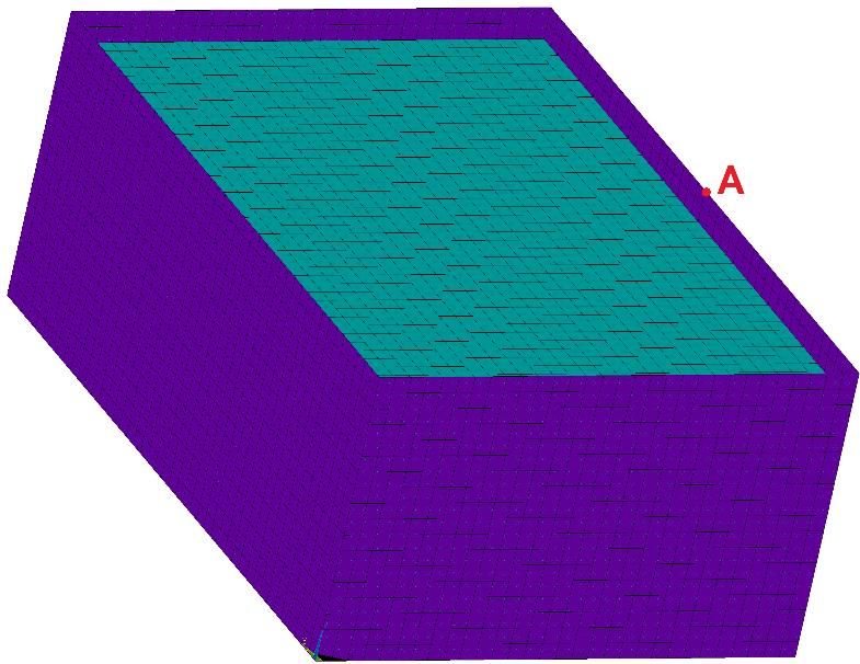
The tank analyzed in this article is a rectangular, above-ground, reinforced concrete tank with
a fixed bottom plate. The ground plan dimensions are 11.0 m x 7.5 m and its height is 4.5 m.
The filling in the tank is water, its level reaches to a height of 4 m, which limits the possibility
of splashing under dynamic load. The static model of the tank made using the finite elements
is shown in Fig. 1.
*
Corresponding author: norbert.jendzelovsky@stuba.sk
© The Authors, published by EDP Sciences. This is an open access article distributed under the terms of the Creative Commons
Attribution License 4.0 (http://creativecommons.org/licenses/by/4.0/).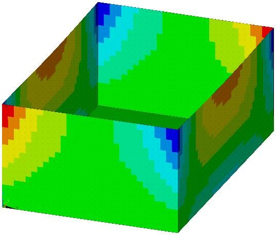
MATEC Web of Conferences 313, 00022 (2020)                     https://doi.org/10.1051/matecconf/202031300022
DYN-WIND´2020

     Fig. 1. FEM model of the tank.

         The SHELL181 quadrilateral planar shell element was used in the ANSYS program for
     static modeling of tank walls with a thickness of 200 mm and tank bottom with a thickness
     of 500 mm. The liquid 3D element FLUID80 was used for modeling water as a tank filling.

     3 The Accelerogram
     The input value for a dynamic calculation was the earthquake accelerogram (Fig. 2). Its time
     step is 0.01 s.

       a (m/s²)
       2,50
       2,00
       1,50
       1,00
       0,50
       0,00
      -0,50
      -1,00
      -1,50
      -2,00
      -2,50
      -3,00
      -3,50
              0     1        2        3        4       5          6       7        8       9       10
                                                    Time (s)

     Fig. 2. Accelerogram of an applied earthquake (Varpalota, 1995, Hungary).

         This accelerogram was imported into ANSYS software. We considered a 2% damping of
     the structure (recommended for reinforced concrete structures). The amount of damping was
     taken into account using Reyleigh damping (set values α = 0.741525 and β = 0.0005391).

                                                     2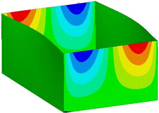
MATEC Web of Conferences 313, 00022 (2020) https://doi.org/10.1051/matecconf/202031300022
DYN-WIND´2020
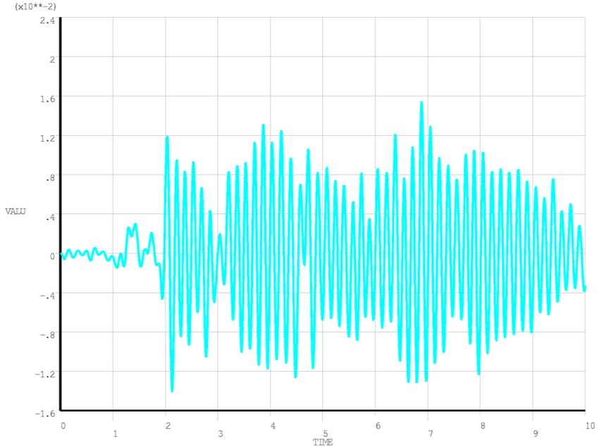
In Fig. 3 there is a graph showing the horizontal displacement of one point in time. This
point is located on the upper edge in the middle of the longer wall (point A in Fig. 1). In this
point, the maximum displacement values have been reached.
Fig. 3. Displacement of the point in the x-axis direction (m) in time (point A in Fig. 1).
The specific time t at which the displacement reached its highest value was t = 6.88 s. At
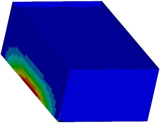
this time, the deformations of the tank were plotted in the x-axis direction (Fig. 4) and in the
y-axis direction (Fig. 5). The caption of the figure presents the maximum values of
deformation of the tank walls.
Fig. 4. Deformation in the x-axis direction at Fig. 5. Deformation in the y-axis direction at
time 6.88 s (ux = 15.429 mm). time 6.88 s (uy = 1.377 mm).
3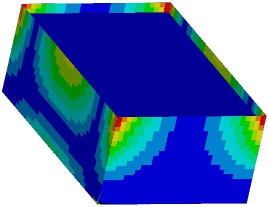
MATEC Web of Conferences 313, 00022 (2020)                        https://doi.org/10.1051/matecconf/202031300022
DYN-WIND´2020

        The specific bending moments in the tank walls mx (Fig. 6) and my (Fig. 7) at time t =
     6.88 s were also plotted on the structure.

       Fig. 6. Specific moment mx in the tank walls at       Fig. 7. Specific moment my in the tank walls at
       time 6.88 s (maximum mx = 46.004 kNm/m).              time 6.88 s (maximum my = 46.004 kNm/m).

         Water at the investigated time (t = 6.88 s) reached the largest deformation in the z-axis
     direction, with the wave size of 118.85 mm (Fig. 8). The water level at rest is 500 mm lower
     than the walls, so there is no risk of splashing out of the tank.

     Fig. 8. Waving of the water surface in the tank at time t = 6.88 sec. due to earthquake effects (uz =
     118.85 mm).

     4 The response spectrum
     To compare the results from the step-by-step method with the results obtained using the
     simpler spectral method, the response spectrum from the used accelerogram was created.
     This spectrum was generated by means of a subroutine in the RFEM Dlubal calculation
     software and recalculated for different number of time steps. From these courses an envelope
     – response spectrum was created, by which the tank was loaded (Fig. 9).

                                                         4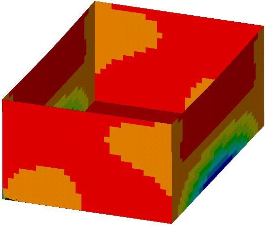
MATEC Web of Conferences 313, 00022 (2020)                          https://doi.org/10.1051/matecconf/202031300022
DYN-WIND´2020

                  12
                  11
                                                                                               Spektrum
                  10
                                                                                               300 steps
                  9
                                                                                               100 steps
                  8
                                                                                               20 steps
      Sa [m/s²]

                  7
                  6
                  5
                  4
                  3
                  2
                  1
                  0
                       0   1        2        3        4         5       6        7        8        9       10
                                                            T [s]

     Fig. 9. Response spectrum obtained from accelerogram (Fig. 2) with 2% damping.

         From the results obtained on the structure of the tank loaded by the response spectrum,
     see Fig. 9, we present the values of maximum tank wall deformations ux (Fig. 10) and uy (Fig.
     11). The maximum reached values have been mentioned in captions of the figures.

             Fig. 10. Deformation in the x-axis direction       Fig. 11. Deformation in the y-axis direction
                      (ux = 16.839 mm).                                  (uy = 2.217 mm).

        The specific bending moments in the tank walls mx (Fig. 12) and my (Fig. 13) were also
     plotted on the structure.

                                                            5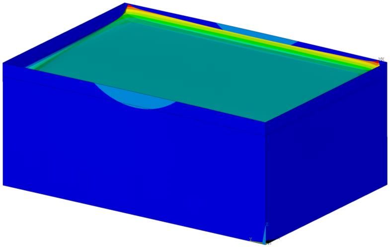
MATEC Web of Conferences 313, 00022 (2020)                     https://doi.org/10.1051/matecconf/202031300022
DYN-WIND´2020

       Fig. 12. Specific moment mx in the tank walls       Fig. 13. Specific moment my in the tank walls
               (maximum mx = 51.054 kNm/m).                         (maximum my = 90.651 kNm/m).

     5 Comparison of results
     As it can be seen in Table 1, when applying the accelerogram loading and response spectrum
     loading (obtained from the given accelerogram), there is a difference in both the resulting
     deformations and the specific moments in the walls. The values obtained by spectral analysis
     are higher. This confirms the correctness of both calculations since the results obtained from
     the response spectrum should be higher than those obtained by direct integration over time.

      Table 1. Comparison of deformations and specific moments during an earthquake with 2% damping.

                                               Accelerogram          Spectrum

                                ux [mm]            15.429              16.839

                                uy [mm]            1.377               2.217

                              mx [kNm/m]           46.004              51.054

                              my [kNm/m]           87.527              90.651

     This paper was written with the support of Slovak Grant Agency VEGA 1/0412/18, and KEGA
     025STU-4/2019.

                                                       6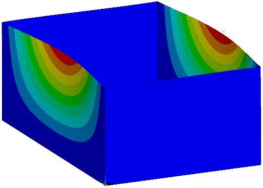
MATEC Web of Conferences 313, 00022 (2020)                https://doi.org/10.1051/matecconf/202031300022
DYN-WIND´2020

     References
     1.   M. Sokol, K. Tvrdá, Dynamika stavebných konštrukcií (Bratislava, STU v Bratislave
          2011)
     2.   K. Kotrasová, E. Kormaníková, A case study on seismic behavior of rectangular tanks
          considering fluid Structure interaction. International Journal of Mechanics, 10, 242-252
          (2016)
     3.   K. Kotrasová, I. S. Leoveanu, E. Kormaníková, A comparative study of the seismic
          analysis of rectangular tanks according to EC8 and IS 1893. Buletinul AGIR, 18, 3, 120-
          125 (2013)
     4.   K. Kotrasová, E. Kormaníková, Hydrodynamic analysis of fluid effect in rigid
          rectangular tank due to harmonic motion, 9th International Conference on Material in
          Engineering Practice 2014, Herlany, Slovakia, (2014)
     5.   J. Kala, V. Salajka, P. Hradil, Response of water tower on wind induced vibration
          considering interaction of fluid and structure. 2nd International Conference on
          Engineering and Technology Innovation, Taiwan, pp. 1269-1272 (2012)
     6.   R. Cajka, P. Mynarcik, J. Labudkova, Numerical solution of soil-foundation interaction
          and comparison of results with experimental measurements. International Journal of
          GEOMATE, 11, 2116-2122 (2016)

                                                  7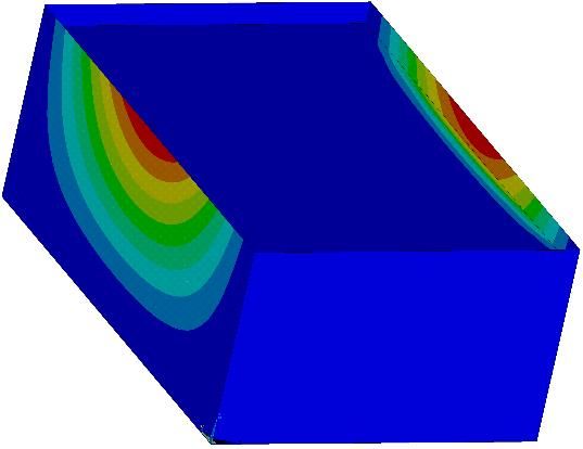
You can also read