San Juan Mining Corporation Operations Plan San Juan Ridge Mine Nevada County, California
←
→
Page content transcription
If your browser does not render page correctly, please read the page content below
San Juan Mining Corporation

      Operations Plan

     San Juan Ridge Mine

  Nevada County, California

          January 2012

          Prepared by:

          P.O. Box 1945

      Nevada City, CA 95959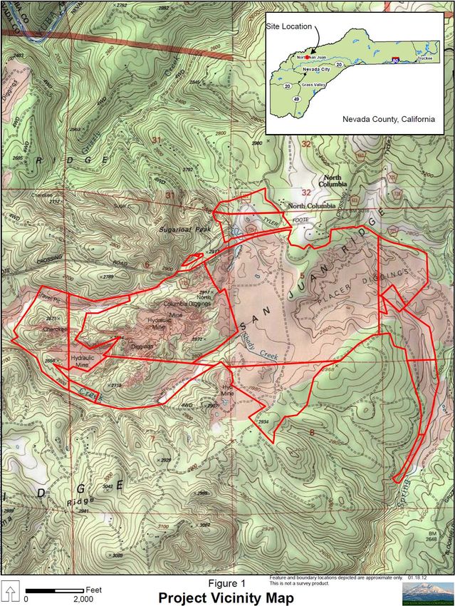
GENERAL INFORMATION

Location and Access

The San Juan Ridge Mine property is located approximately 17 miles north of the town of Nevada
City, Nevada County, California, and 0.3 miles south of the former mining town of North Columbia
(Figure 1). Nevada City is approximately 55 miles north east of Sacramento, California.

Access to the property from Nevada City is via State Highway 49 for nine miles to Tyler-Foote
Crossing, then east on Tyler-Foote Crossing Road for eight miles to North Columbia. The property
is transected by the Fire Access Road (Jackass Flat Road).

See Figure 1

General Site Condition

The San Juan Gold property is situated in a topographically high area known as San Juan Ridge,
which is 700 to 900 feet above and between the Middle Yuba and South Yuba Rivers. The elevation
of the property is between 2,600 and 3,000 feet above sea level.

Annual precipitation averages 5 2 inches of which approximately 90 percent f alls during a six
month period between November and April. Snow is sporadic during winter months, b u t should not
affect operations.

Property Description

The following A.P. numbers identify the entire property. Zoning is FR-40-ME.

   •   61-140-42,
   •   61-140-47,
   •   61-140-48,
   •   62-050-40,
   •   61-130-03,
   •   61-130-04,
   •   61-130-10,
   •   61-130-19,
   •   61-260-17,
   •   62-050-41,
   •   61-130-22,
   •   61-110-04,
   •   61-120-01,
   •   61-120-02,
   •   61-120-04,
   •   62-060-02,
   •   62-070-02

The San Juan property consists of approximately 1,700 acres of patented land. This property was
acquired in 2 0 1 1 by San Juan Mining Company
Project Summary

The San Juan Ridge Mine property consists of approximately 1,700 acres of patented land located
in Nevada County, California. The property was first mined during t h e California Gold Rush as an
open pit hydraulic mine. This method was used until the Sawyer Decision of 1886 prohibited a n y
further unrestricted use. The San Juan Ridge deposit was last mined in the early to mid 1990’s
as an underground room and pillar operation.

San Juan Mining Corporation desires to reopen the San Juan Ridge Mine and resume mining activities
while utilizing current advancements in technology, equipment, and computer modeling to reduce
environmental impacts, promote a safe working atmosphere and increase the efficiency of the operation.

Underground mining and processing will be accomplished by well proven methods using standard mining
equipment and simple gravity extraction to remove gold.

The project will span approximately 11 years after rehabilitation of the site and underground workings.
Concurrent reclamation methods will be utilized to limit disturbed areas as mining progresses. The after
mine land use will not be affected, but some improvements, i.e., power transmission lines, roads, and
buildings will be left in place.
GENERAL MINE DESCRIPTION

Start-Up and Surface Rehabilitation

Conditional Use Permit (CUP) approval would initiate a 17 month rehabilitation campaign to reopen the
San Juan Ridge Mine. During this time, CUP conditions will be addressed/mitigated and final project
engineering completed. Project financing will be finalized and long lead time equipment will be
purchased. All final site drawings will be completed, accessory permits obtained and any “outside”
contracting finalized.

San Juan Mining Corporation’s internal staff will accomplish the majority of the site rehabilitation work.
Initial project staff, approximately 20 employees, will be hired and trained prior to the beginning of this
period.

The mine rehabilitation period will begin with the restoration and improvement of existing access roads.
Approximately six (6) miles of existing roads will be upgraded and left in place as property
improvements after closure.

Existing 12 KV transmission lines necessary for the project, originally installed by Pacific Gas & Electric,
will be repaired and inspected. It is planned to leave these transmission lines intact as property
improvements after closure. A dedicated easement to Pacific Gas & Electric will insure the
improvement. Specific power distribution systems will be rehabilitated by a certified electrical
contractor. Project lighting around surface stationary and mobile structures will be designed to be low
intensity, downward-facing and installed only in locations that will improve the safety and security of
the site.

Rehabilitation of mine facilities such as offices, shop, storage, change house, freshwater distribution,
sewage disposal systems, surface plant, and refinery will be completed during this period. Construction
of surface mobile structures and the mine dewatering network will also take place during this period

By the end of the rehabilitation phase of the San Juan Ridge Mine re-opening all project personnel will
have been hired and trained. Approximately 78 employees will be employed at project initiation.

.

Underground Rehabilitation

The ore body was previously accessed by an 1,800 linear foot decline grading at -10%. The dimensions
of the decline are approximately 14 feet high by 14 feet wide. The decline was installed at the
Southeast property boundary to allow construction in bedrock rather than gravels. At the terminus of
the decline, previous development work included the construction of openings required for the
underground screening operation, muck bays, and access to the main ore deposit. Approximately 1,400
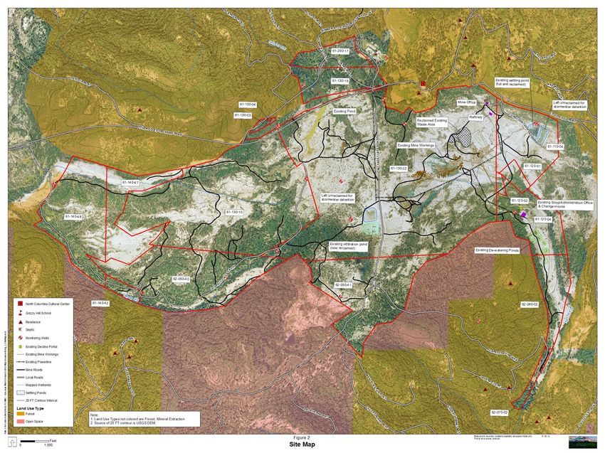
linear feet of excavations along the ore body were created in the defined ore zone by the previous
operator. Rehabilitation of the underground workings will require re-accessing the decline which is
currently sealed. Underground excavations will require preliminary inspections and additional ground
control to insure the safety of the underground work area. The underground processing plant, water
and electric utilities, and the ventilation network will also be installed during the rehabilitation phase.

The excavations surrounding the underground plant location will also be rehabilitated and used again to
stockpile mined material. A 1,000 cubic yard stockpile was created to accommodate a decoupling of the
mining/processing cycle in the event either operation suffers an unexpected breakdown. At selected
intervals throughout the mine’s operating life, new underground plant and surface plant stations will be
created and the equipment relocated. Advancing the plant locations to the West in concert with mining
activities will mitigate haulage distances underground.

See Figure 2 for a map of existing surface and subsurface infrastructure.
Figure 2-Existing Surface and Subsurface Infrastructure
Production-Years 1 to 10

Annual Surface Definition Drilling

An ongoing drilling program, conducted from the surface, will provide sampling points in the ore horizon
to better define the extent of the mineable ore body. Although a vast amount of definition drill has
already been performed on the San Juan Deposit, it will be necessary to incorporate additional
geostatistical information to improve the accuracy of the operation as mining advances.

It is anticipated that only 25 definition drilling holes will be required per year to better define the ore
boundaries. Hole depth will vary from 300 to 500 feet depending on the surface drilling location. Only
the bottom 40 feet of the hole will be sampled. Samples will be collected for each 5 foot interval over
the bottom 40 feet of the hole.

Drilling ventilation holes and secondary escapeways as per Mine Safety & Health (MSHA) and California
Division of Occupational Health and Safety (CalOSHA) requirements will also be required. These holes
could range from 30 to 120 inches in diameter to provide adequate ventilation to underground
employees.
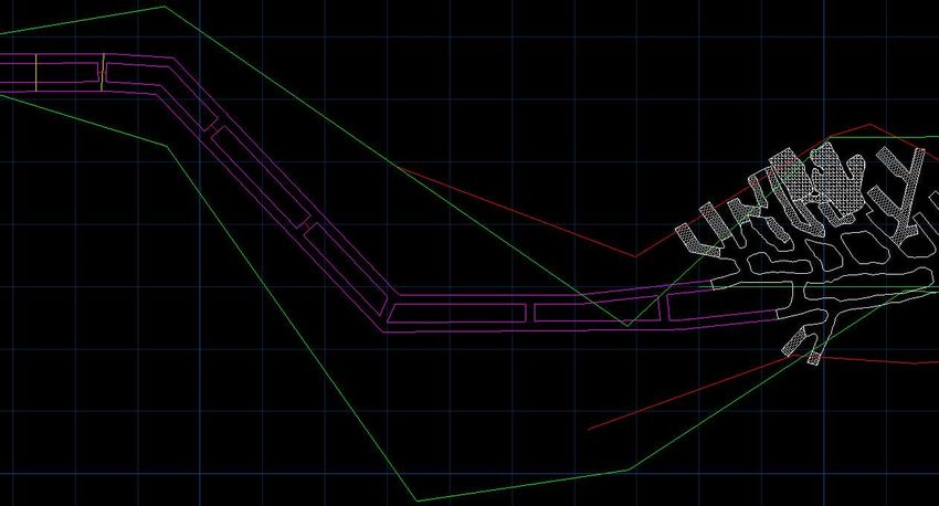
Annual Development Work

Two parallel development entries will be excavated in the approximate center of the defined ore body
and progress Westerly to the terminus of the outlined ore zone. They will be separated by a 30 foot
wide pillar of in-situ rock with cross cuts connecting them on 230 foot centers. The amount of
development work will change yearly as a function of the ore body width. It is expected that 20-40% of
the total mine production will be from development excavation.

                                        Figure 3-Development Mining

Mining

New mining activities will commence at the Western extent of the current excavation and progress
Westerly along the defined ore body. Two parallel development entries will be driven along the gravel
channel with intersecting crosscuts on 230 foot centers. Production panels will be excavated in general
North and South directions from the development entries and extend to the defined boundary of the
gold bearing channel gravels. The panels will be mined using a “leap frog” technique where a solid block
of in-situ material will remain between two excavations. Oversized material from the underground
screening plant will be backfilled into the two excavated panels and allowed to solidify. After the
backfilled material has congealed the block of in-situ material original left between them will then be
extracted. By using this technique the amount of open excavated ground will be reduced and the global
ground support of the mine improved. During the first year of production an estimated 122,000 bank
cubic yards (BCY) of material will be mined, at an average daily production of 622 BCY. This represents a
reduced mining rate from the anticipated 1,000 BCY per day for the remainder of the operational life
(196,000 BCY per year). This was done to allow for both site and equipment familiarization of the mine
personnel and to gain experience with the deposit. These production volumes are anticipated to be
obtained during a four day work week operating two, 10 hour shifts per day. It may be necessary
throughout the life of the operation to increase the work schedule to accommodate for non-production
days due to mechanical breakdown, inclement weather or other unforeseen occurrences.
Figure 4-Panel Mining
It is anticipated that the full extraction method planned for the deposit will be a workable solution,
giving consideration to:
1. The structural behavior of the cemented gravels and their ability to stand intact over relatively
long periods of time
2. The proposed backfilling activity wherein oversized material from the underground screening
plant will be returned to the excavations, thereby reducing the span of open ground at one
particular time
It is assumed that 15% of the resource will remain in the mine was un-minable pillars, either because of
the need for special ground support or because the gold content of the pillar does not warrant the
associated costs or removal.
Approximately 60% of the mined gravel is forecast to be larger than ¼ inch in size; this will constitute the
screen reject fraction to be used as backfill. In the late 1960’s the U.S. Geological Survey performed
testing on the Badger Hill property (a Northwestern extension to that portion of the channel assessed in
the report) with the following results:Size Fraction % of Total Material
+64 mm 13
4-64 mm 56
1/16-4mm 28
-1/16 mm 3
100
Subsequent drilling and testing by private corporations, conducting exploration on the San Juan deposit
proper, indicated that the distribution of the particle sizes within the higher grade gravel section (the
material scheduled for underground mining) would be closer to a 60/40 split at the ¼ inch target size.
The ¼ inch fraction is deemed important at this property because testing has shown that very little gold
occurs in particles larger than this dimension.
Screen undersize ( the – ¼ inch fraction) will be collected underground and pumped to the surface as a
slurry through a lined borehole. From there it will pass through the gold recovery plant. As the plant is
periodically repositioned underground, so too will be the pumping station. A new borehole will be
drilled from the surface each time, and the surface plant will be relocated correspondingly to reduce
pumping costs.
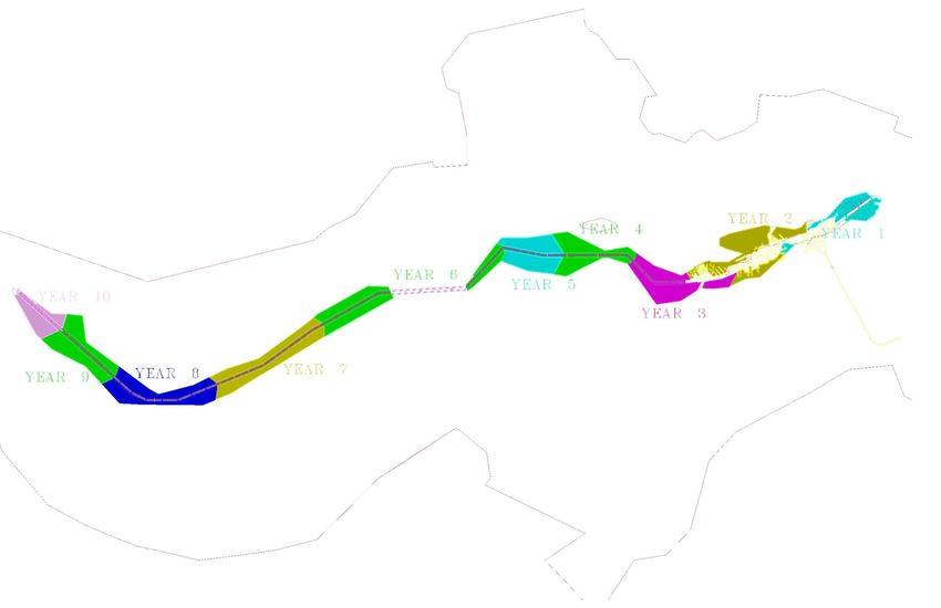
Once full production starts in Year 2, ore will be processed at a rate of 196,000 BCY per year until the
deposit is exhausted in Year 10. The remainder of Year 10 will allow for production loss makeup and
initial reclamation. The total volume produced is estimated to be 1,869,896 BCY. As stated previously,
an estimated 15% of the ore body will remain in-situ as additional ground support or low grade pillars. A
second assumption is that dilution will average 12%. The average height of the mine horizon is expected
to be 16.7 feet, and up to 26 feet in some zones.Figure 5-Yearly Mine Production
Mineral Recovery Process

Processing of the ore will be by attrition scrubbing to liberate the free gold particles followed by gravity
methods for their concentration and recovery. The scrubbing and initial screening will be done
underground to minimize the amount of material transported to the surface. Material – ¼ inch in size
will be transported to the surface as a water slurry for initial concentrating.

Initial concentration on the surface plant will be done with a vibratory screen and centrifugal
concentrator, with the oversized material (- ¼ inch to +2 Tyler mesh) discharging into a course gold
sluice. The – ¼ inch waste from the concentrator will be de-slimed by an oversized sand screw with the
slimes going to a settling pond and the – ¼ solids being stacked for disposal. This plant will be covered
for noise attenuation purposes. No chemicals or toxic substances will be used in the recovery process.
All the proposed processing equipment relies completely on water and gravity separation methods.
Figure 6-Underground Processing Plant
Figure 7-Surface Processing Plant
Final Concentrate Processing

Product from the centrifugal concentrator will be collected and transported to the refinery. The refinery
will be a permanent enclosed structure located near the main office/main gate for security purposes.
Final gold concentration will include a smaller centrifugal concentrator, shaking tables and rotary
wheels. Dore will be produced by furnace melting of the final recovered free gold. If final mineral
concentrate contains metals at toxic levels, they will be treated as a hazardous material. Concentrates
are frequently a saleable product because of the presence of certain metals. The minerals will either be
disposed of as a hazardous waste or sold as a product. Mineral concentrates are expected to be
generated at a maximum rate of 1,440 pounds per day or 90 tons per year. Storage for disposal will not
exceed 90 days.

Concentrates will be stored in accordance with applicable local, State, and Federal regulations.
Concentrate materials are excluded from federal hazardous waste regulations under 40CFR 261.4 (b)(7).
Therefore, EPA hazardous waste generator registration will not be required. No chemical or toxic
substances will be used in the final recovery circuit.
Figure 8-Gold Refinery
Mine Closure- Year 10 and Year 11

When the deposit is depleted in Year 10, all machinery and infrastructure will start to be removed from
the underground areas. The workings will be thoroughly inspected for trash, scrap and other debris
before the dewatering system is shut down and removed. The decline portal, ventilation, escapeways
and other accesses into the mine will be sealed as per Federal, State and Local regulations.

All surface equipment, except permanent roads, permanent buildings and power transmission lines will
be dismantled and stored at the shop area until they are sold. Mobile mining equipment will be
refurbished at the shop area and stored until sold. All process piping will be cleaned and stored. Power
distribution systems will be dismantled and stored.

All surface areas for mine facilities that are dismantled will be reclaimed. Final reclamation of all
disturbed areas will be completed per the Reclamation Plan.

Temporary Mine Closure

A temporary closure could result for one of several conditions beyond the operator’s control. Among
other things, this could be caused by a depression in gold prices, an act of nature, civil unrest or labor
shortages because of war.

Temporary closure will be defined as:

    1. Any stoppage of work exceeding 90 days in length but limited to 5 yaers.
    2. The reduction employment by 75% over the amount employed during the previous six month
       period.
    3. A temporary mine closure can only occur during the production years 1-10.
    4. Will not constitute part of the 11 year mine life.

In the event of a temporary closure, disturbed areas will be reclaimed per the Reclamation Plan. Waste
areas will be re-contoured to prevent erosion and re-vegetated. Temporary erosion control measures
will be implemented per the Reclamation Plan when and where needed.

Mine dewatering would continue as designed. Underground mining equipment would be removed and
stored at the shop area. A small maintenance crew would take care of dewatering activities and any
reclamation/erosion maintenance required.
GENERAL MINE DESIGN All operation plans were designed to minimally impact the environment and community. All stationary surface machinery will be covered and located as to minimize noise. There will be minimal off site visual impacts. Waste disposal areas were specifically designed to negligibly alter the site topography during and after mining. A mine life total of 162 acres will be disturbed. This will include area needed for surface storage of oversized material from the mine, tailings from the gold recovery process, and site locations for the mobile surface plant. Concurrent reclamation will limit the maximum disturbed area at any one time to 32 acres with about 28% of this occupied by mine operation facilities and access roads. Surface storm runoff will be collected and channeled to minimize off site turbidity. No operations will be conducted in the perennial stream areas except for access road crossings. Excess mine water will be returned to the ground via an infiltration system. Settling Ponds-Design During the previous operation of the San Juan Ridge mine two settling ponds were created with finished full poll dimensions of 2.3 acres and were used to remove slimes from process water. One pond was utilized by the prior operator and has subsequently been reclaimed. The second pond is in usable condition and will be utilized as the first settling pond for process water under the proposed project. Subsequent ponds will be of similar dimension and design. The 48 acre/feet ponds will provide enough retention time to clarify the process water. Initial process water, estimated 24 million gallons, will be pumped from existing wells. Any make-up water required will also be pumped from wells and/or be taken from the mine dewatering network. The ponds have been over designed by 20 percent, plus enough freeboard to contain 2-100 year 24 hour storms. The integrity of the ponds are ensured by excavation in native sediments, without any embankment (fills) below the “full pond” levels. Additional ponds will need to be constructed as mining progresses Westerly along the gravel channel. It is estimated that 10-12 additional ponds of similar size will need to be created over the life of the project.
Figure 9-Settling Pond Design (Plan View)
Figure 10-Settling Pond Design (Cross Section)
Blasting

Proposed mining equipment consists of an electrically powered continuous mining machine that will be
used to break the cemented gravel deposit. Using this system a majority of the deposit can be mined
without the use of explosives. If a section of rock is encountered that has a uniaxial compressive
strength which exceeds the capabilities of the continuous mining machine, it will be necessary to use
explosives to remove the hardened zone. Based upon previous monitoring at the site, blasts will not be
perceptible from the surface.

Underground Secondary Escapeway

Federal and state mine safety orders require underground mines to provide an alternative means of
access/escape in the event of a surface or underground emergency. The number of, size, and type of
construction are determined by the agencies for each specific mine. Two shafts have already been
excavated into the mine horizon and will be utilized as secondary escapeways under the proposed
project. As mining progresses it will be necessary to excavate additional shafts to accommodate
applicable orders. An additional 3-5 shafts will be required, spaced approximately 3,000 feet apart,
ranging in size from 36 inches to 120 inches in diameter.

Ventilation

Federal and state mine safety orders require that fresh air be provided to miners underground at the
rate of 200 cubic feet per minute (CFM) per person. The regulations also require that fresh air be
provided at the rate of 100 CFM per horsepower for diesel equipment operating underground.

Initially during the rehabilitation of the access decline and existing underground workings, fresh air will
be forced underground via a 40 horsepower (hp) and 200 hp fans through 28” ventilation tubing. Fans
will be underground from the start of the rehabilitation effort. Once production has commenced, fans
will be moved to the two installed ventilation shafts, thus “sucking” fresh air down the decline and
exhausting it through the vertical shafts to the surface. These shafts are also intended to be used as
secondary escape ways from the underground workings.

Mine Pumping System

A main underground sump will be re-established underground and a multistage turbine pump capable
of discharging 500-1,600 gallons per minute (gpm) at a 350 foot head. An 8 inch pipeline will be
established underground that will receive water from additional sumps near the production areas as the
mine advances. The 8 inch line will carry water to the main sump for discharge to the surface. On the
surface the mine discharge water will flow into a settling pond through a similar pipe network. Water
infiltration/settling ponds were created during the previous operation of the mine and with minimal
rehabilitation may be used again under the proposed project. These ponds were designed to provide a
minimum 4 hour retention time plus contain a 24 hour, 100 year storm event. Water from the settling
pond will flow through an 8 inch overflow pipe to an infiltration pond. The infiltration pond will be an
additional clarifier and also prevent direct discharge to surface waters. Soil mantle and percolations
tests were completed by Dale Huber Engineering.
Figure 1-General Site Water Balance
Mine Equipment Water and Potable Water

Mine water and potable water will be pumped from one of the existing wells a 10,000 gallon storage
facility from which it will be distributed to the mine, mine office, change house, main office and refinery.
A pump will send water to the storage facility on a continuous basis, so the take should remain full or
nearly full on a constant basis.

PROJECT FEATURES

Planned Schedule

Site Rehabilitation                                                                        Operating Shifts         Shifts/Week
Start Up & Rehabilitation
             General Site Rehabilitation                                                             22                     4
             Electrical System Repair                                                                15                     4
             Office and Shop Building Repair                                                         20                     4
             Install Surface Mobile Equipment                                                        45                     4
           * Decline Rehabilitation                                                                 135                     4
             Underground Ground Control,                                                             91                     4
           * Equipment and Utilities

The total duration of the Rehabilitation Phase is expected to take 17 months
* Underground work i s expected to i ncrea s e to two s hi fts per da y a fter the i ni ti a l 12 weeks of decl i ne reha bi l i ta ti on
Staffing Requirements Employees
Rehabilitation 20
Production Year 1-Year 2 78
Production Year 3-Year 4 82
Production Year 5 84
Production Year 6 86
Production Year 7-Year 8 90
Production Year 9-Year 10 92
Mine Closure 92 to 5
Estimated Annual Production Ore (BCY) -1/4) Waste BCY
Rehabilitation 0 0
Production Year 1 122,500 49,000
Production Year 2-9 196,000 78,400
Production Year 10 179,396 71,758
Mine Closure 0 0
TOTAL 1,869,896 747,958
Consumable Supplies
Diesel and gasoline will be used in surface and underground mobile equipment interan combustion
engines. Fuel will be stored near the shop in above ground tanks with containment berms per
applicable Federal, State, and Local regulations. A maximum of 10,000 gallons of diesel and 1,000
gallons of gasoline will be stored on site. An underground storage facility for diesel fuel and lubricants
will also be constructed with a maximum size of 5,000-8,000 gallons.
Lubricating oils and grease will be stored in their respective shipping contains until dispensed to surface
and underground equipment. The containers will be stored in designated fire safe areas and/or flame
resistant cabinets. Used lubricating oils will be stored in an above ground tank with containment and be
disposed of through a licensed California waste oil recycler. Grease saturated rags and oily waste will be
stored in a covered fire proof container for eventual approved storage.
Oxygen and acetylene will be used for repair and fabrication on for all mining equipment. The cylinders
will be stored in a designated area of the shop until used and in accordance with all MSHA and CalOSHA
regulations.Cement will be used for concrete and shotcrete production to improve the stability and safety of underground openings. Cement will be delivered by bulk suppliers and stored in a 25-50 ton silo on the surface or near the warehouse area if delivered in 2,000 pound super-sacks. Explosives will be used exclusively underground to break hardened ore prior to processing. Blasting agents, dynamite, cast boosters, and non-electric blasting caps are the types of explosives that will be used. All explosives will be delivered to the job site by a supplier by transportation routes approved by the California Highway Patrol and other local agencies. Upon delivery all blasting agents will be transported and stored underground using company equipment outfitted with specific safety devices required for the transportation and storage of explosives. A maximum of 40,000 pounds of explosives will be stored on site. When the project is terminated or closed temporarily for any reason, all explosives will be returned to the supplier. Propane will be used for heating offices, shop, change house, refinery, and surface plant areas. Five 500 gallon tanks will be installed and serviced by a propane supplier. Material Used Quantities Used/Year Dynamite 50,000 lbs ANFO 300,000 lbs Diesel 500,000 gal Gasoline 20,000 gal Lubricating Grease 12,000 lbs Lubricating Oils 6,000 gal Hydraulic Oils 8,000 gal Cement 6,00 tons Oxygen 7,000 cuft Acetylene 5,000 cuft Propane 10,000 gal
PROJECT EQUIPMENT

                                                                Annual
Site General                        Condition Type Horsepower   Hours
Powerline, Substation, Switchgear    Existing
Domestic Water                       Existing Electric 20        NA
Sewage                               Existing

SUB TOTAL
ELECTRIC HP               20
DIESEL HP                  0

                                                                Annual
Service and Ancillary Buildings     Condition Type Horsepower   Hours
Main Office 24'x60'                  Existing
Main Shop 40'x100'                   Existing
Storage 40'x40'                      Existing
Safety Equipment                      New
Shop Compressor                       New     Electric
Compressor Building                  Existing
Shop Tools & Crane                    New     Electric
Fueling Island                       Existing
Cassette Truck                        New      Diesel  148      1,500
RTV                                   New      Diesel  16        500
Pressurewasher                        New      Diesel  25        70
Diesel Welder                         New      Diesel  19        170

SUB TOTAL
ELECTRIC HP               430
DIESEL HP                 208
Annual
Surface Equipment Condition Type Horsepower Hours
Tractor Used Diesel 84 1,170
Dozer Used Diesel 145 340
Backhoe Used Diesel 98 1,170
Telehandler Used Diesel 125 340
Surface Foreman
New Diesel 355
Truck 1,500
Surface Crew Truck New Diesel 355 500
Surface Buggy New Diesel 16 1,500
Water Truck Used Diesel 430 850
Dump Trailer New NA
Skidsteer Used Diesel 45 340
Wheel Loader Used Diesel 145 670
Articulated Truck Used Diesel 265 670
Concrete Batch Plant Used Electric 150 500
Tripple Deck Screen Used Diesel 150 300
SUB TOTAL
ELECTRIC HP 150
DIESEL HP 2213
Annual
Underground Equipment Condition Type Horsepower Hours
Tractor New Diesel 50 2,500
Tractor New Diesel 50 2,500
Tractor NEw Diesel 50 2,500
Tractor New Diesel 50 2,500
Crawler Dozer Used Diesel 85 1,170
LHD New Diesel 201 1,170
Excavator Used Diesel 57.6 500
Motor Grader New Diesel 48 2,000
Wheel Loader Used Diesel 145 2,500
Skidsteer Used Diesel 45 340
Tractor New Diesel 50 2,300
Scissor Lift Truck New Diesel 148 2,170
Telehandler Used Diesel 101 500
Roadheader New Electric 541 1,800
Scissor Lift Truck Used Diesel 148 1,670
Air Compressor Used Diesel 61 500
Shotcrete Aplicator New Diesel 148 2,000
Transmixer New Diesel 160 2,000
Transmixer New Diesel 160 2,000Teledumpter New Diesel 400 3,400
Teledumpter New Diesel 400 3,400
Teledumpter New Diesel 400 3,400
Shotcrete Pump New Diesel 110 3,170
Crawler Dozer Used Diesel 85 3,170
LHD New Diesel 201 3,170
SUB TOTAL
ELECTRIC HP 541
DIESEL HP 3354
Annual
Ventilation & Pumping Condition Type Horsepower Hours
Fan New Electric 200 4,704
Fan New Electric 40 4,704
Fan NEw Electric 30 2,352
Fan New Electric 30 2,352
Fan New Electric 30 2,352
Pump New Electric 250 8,760
Pump New Electric 150 8,760
Pump New Electric 6 8,760
Pump New Electric 6 9,490
Pump New Electric 6 10,220
Pump New Electric 6 10,220
Pump New Electric 15 8,760
Pump New Electric 15 8,760
Pump New Electric 15 9,490
Pump New Electric 15 8,760
SUB TOTAL
ELECTRIC HP 814
DIESEL HP 0
Gold Recovery Annual
Circuit Condition Type Horsepower Hours
Underground Plant New Electric 500
Surface Plant New Electric 100
Gold Refinery Used Electric 50
SUB TOTAL
ELECTRIC HP 650
DIESEL HP 0TOTAL DIESEL HP 5,775 TOTAL ELECTRIC HP 2,605
You can also read