SCNDR Handheld Barcode Scanning for your Allen-Bradley PLC ScanDr. Package User Guide - Real Time Automation
←
→
Page content transcription
If your browser does not render page correctly, please read the page content below

SCNDR
                        Handheld Barcode Scanning
                         for your Allen-Bradley PLC
                        ScanDr. Package User Guide
                                  Package Revision 1.02

Real Time Automation®         1                 800-249-1612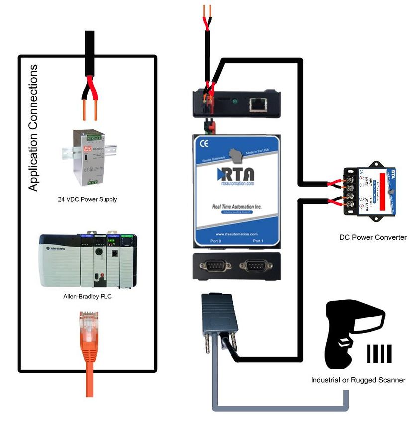
Trademarks

CompactLogix, ControlLogix, & PLC-5 are registered trademarks of Rockwell Automation, Inc. EtherNet/IP is a
trademark of the ODVA. MicroLogix, RSLogix 500, and SLC are trademarks of Rockwell Automation, Inc. Microsoft,
Windows, and Internet Explorer are registered trademarks of Microsoft Corporation. BACnet® is a registered
trademark of American Society of Heating, Refrigerating and Air-Conditioning Engineers (ASHRAE). All other
trademarks and registered trademarks are the property of their holders.

Zebra is a registered brand of © 2018 ZIH Corp and/or its affiliates. All rights reserved. Zebra and the stylized Zebra
head are trademarks of ZIH Corp., registered in many jurisdictions worldwide.
.
All other trademarks and registered trademarks are the property of their holders.

Limited Warranty

Real Time Automation ® warrants that this product is free from defects and functions properly.

EXCEPT AS SPECIFICALLY SET FORTH ABOVE, REAL TIME AUTOMATION, INC. DISCLAIMS ALL OTHER
WARRANTIES, BOTH EXPRESSED AND IMPLIED, INCLUDING BUT NOT LIMITED TO IMPLIED WARRANTIES
OF MERCHANTABILITY OR FITNESS FOR A PARTICULAR APPLICATION. THIS LIMITED WARRANTY GIVES
YOU SPECIFIC LEGAL RIGHTS. YOU MAY ALSO HAVE OTHER RIGHTS, WHICH VARY FROM STATE TO
STATE.

The examples and diagrams in this manual are included solely for illustrative purposes. Because of the many
variables and requirements associated with any particular application, Real Time Automation, Inc. cannot assume
responsibility or liability for actual use based on the examples and diagrams. Except as specifically set forth above,
Real Time Automation and its distributors and dealers will in no event be liable for any damages whatsoever, either
direct or indirect, including but not limited to loss of business profits, income, or use of data. Some states do not allow
exclusion or limitation of incidental or consequential damages; therefore, the limitations set forth in this agreement
may not apply to you.

No patent liability is assumed by Real Time Automation with respect to use of information, circuits, equipment, or
software described in this manual.

Government End-Users

If this software is acquired by or on behalf of a unit or agency of the United States Government, this provision applies:
The software (a) was developed at private expense, is existing computer software, and was not developed with
government funds; (b) is a trade secret of Real Time Automation, Inc. for all purposes of the Freedom of Information
Act; (c) is “restricted computer software” submitted with restricted rights in accordance with subparagraphs (a)
through (d) of the Commercial “Computer Software-Restricted Rights” clause at 52.227-19 and its successors; (d) in
all respects is proprietary data belonging solely to Real Time Automation, Inc.; (e) is unpublished and all rights are
reserved under copyright laws of the United States. For units of the Department of Defense (DoD), this software is
licensed only with “Restricted Rights”: as that term is defined in the DoD Supplement of the Federal Acquisition
Regulation 52.227-7013 (c) (1) (ii), rights in Technical Data and Computer Software and its successors, and: Use,
duplication, or disclosures is subject to restrictions as set forth in subdivision (c) (1) (ii) of the Rights in Technical Data
and Computer Software clause at 52.227-7013. If this software was acquired under GSA schedule, the U.S.
Government has agreed to refrain from changing or removing any insignia or lettering from the Software or
documentation that is provided or from producing copies of the manual or media. Real Time Automation, Inc.

© 2021 Real Time Automation ® All rights reserved.

Real Time Automation®                                         2                                               800-249-1612
Overview ....................................................................................................................................................... 4
Hardware Installation ................................................................................................................................... 6
   Included in your ScanDr. package ............................................................................................................ 6
   Assembling your ScanDr. package ........................................................................................................... 7
   Power Requirements................................................................................................................................ 8
   DIN Rail Installation.................................................................................................................................. 8
Gateway Configuration ................................................................................................................................. 9
   Accessing the Gateway’s Configuration Pages ........................................................................................ 9
   Error: Main Page Does Not Launch ........................................................................................................ 10
   435NBX Setup ......................................................................................................................................... 11
   Connecting CompactLogix, ControlLogix, Flex I/O ................................................................................ 11
   Serial Configuration ................................................................................................................................ 11
   ASCII Configuration ................................................................................................................................ 11
   Connecting MicroLogix, SLC, or PLC5E ................................................................................................... 12
   Saving Changes to the Settings .............................................................................................................. 13
       Optional Functionality......................................................................................................................... 14
       Implement a Heartbeat Using a CompactLogix, ControlLogix, and FlexLogix .................................... 14
       Implement a Heartbeat Using a MicroLogix, SLC or PLC5 .................................................................. 14
PLC Programming ........................................................................................................................................ 15
   RSLogix5000 / Studio5000 Setup ........................................................................................................... 15
   RSLogix500 Setup ................................................................................................................................... 20
Setup Is Complete! ...................................................................................................................................... 21

Real Time Automation®                                                           3                                                           800-249-1612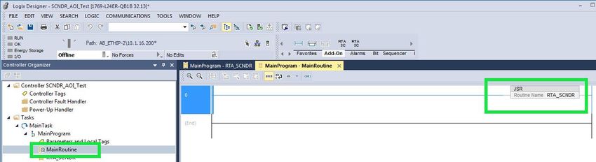
Overview
The ScanDr. package includes everything you need to add handheld barcode scanner(s) to an Allen-
Bradley PLC. This package creates a one source solution for Allen-Bradley PLC applications requiring
handheld barcode scanners. It also simplifies the field integration issues by creating a single voltage
power requirement and single Ethernet connection the Allen-Bradley PLC.

Packages Available
 Part #             Description
 SCNDR-SI1          ScanDr. - Handheld Industrial Corded Barcode Scanner for A-B PLC
 SCNDR-SI2          ScanDr. - 2 Handheld Industrial Corded Barcode Scanners for A-B PLC
 SCNDR-SWI1         ScanDr. - Handheld Industrial Cordless Barcode Scanner for A-B PLC
 SCNDR-SWI2         ScanDr. - 2 Handheld Industrial Cordless Barcode Scanners for A-B PLC
 SCNDR-SR1          ScanDr. - Handheld Rugged Corded Barcode Scanner for A-B PLC
 SCNDR-SR2          ScanDr. - 2 Handheld Rugged Corded Barcode Scanners for A-B PLC
 SCNDR-SWR1         ScanDr. - Handheld Rugged Cordless Barcode Scanner for A-B PLC
 SCNDR-SWR2         ScanDr. - 2 Handheld Rugged Cordless Barcode Scanners for A-B PLC

Real Time Automation®                                4                                       800-249-1612
Materials for commissioning:
All the software tools and reference files needed to commission a ScanDr. package are included on the
provided CD and available online: https://www.rtautomation.com/scandr-support/

SUPPORT
If at any time you need further assistance do not hesitate to call Real Time Automation support.

Support hours are Monday-Friday 8am-5pm CST

Toll free: 800-249-1612
Email: support@rtautomation.com

Real Time Automation®                               5                                      800-249-1612

Hardware Installation
Included in Your ScanDr. Package
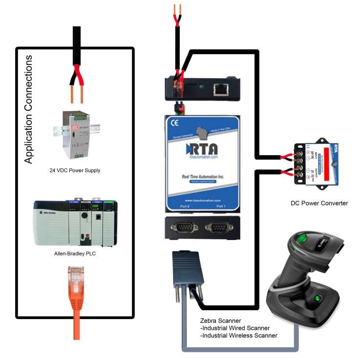
1. Selected Zebra barcode scanner(s)
INDUSTRIAL CORDED INDUSTRIAL CORDLESS RUGGED CORDED RUGGED CORDLESS
Model: DS2208-SR7U2100AZW Model: DS2278-SR7U2100PRW Model: DS3608-SR3U4600VZW Model: DS3678-SR3U42A0SFW
2. RS232 cable: CBA-R01-S07PAR (Industrial) or CBA-RF1-C09ZAR (Rugged)
3. Power convertor & cabling: 24vdc →5vdc convertor with (Industrial 3.5mm jack) or
24vdc → 12vdc convertor with (Rugged 5.5mm jack)
Real Time Automation® 6 800-249-1612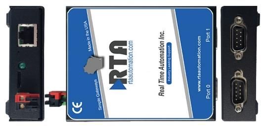
4. 435NBX-N700 ASCII to PLC gateway

Assembling Your ScanDr. Package

   1) Connect the DB9 of the serial cable to the
      male DB9 connection on the 435NBX-
      N700. Attach the mating end into the base
      station or base of the scanner.
          a. For single scanner applications use
              port 0
          b. In 2 scanner applications the
              scanners can be assigned to either
              port

   2) Connect the barrel connector(s) on the
      power wire harness to the mating
      connector on the scanner or scanner base
      station.

   3) Connect the pluggable red & black power
      connector from the power wire harness
      into the 435NBX-N700

   4) Connect the red and black flying leads from
      the power wire harness into a 24VDC power supply.

Real Time Automation®                              7      800-249-1612
Power Requirements
All ScanDr. packages require 24VDC

 Package #                         Power Draw
 SCNDR-SI1                         110mA
 SCNDR-SI2                         175 mA
 SCNDR-SWI1                        284 mA
 SCNDR-SWI2                        522 mA
 SCNDR-SR1                         225 mA
                                                                                                    Spring Loaded Clip
 SCNDR-SR2                         405 mA                                                               on bottom

 SCNDR-SWR1                        1045 mA
 SCNDR-SWR2                        2045 mA
DIN Rail Installation
Follow these steps to install your unit.

        1) Hook the bottom mounting flange under the DIN Rail.

        2) While pressing the 435NBX against the rail, press up to
           engage the spring-loaded lower clip and rotate the unit
           parallel to the DIN Rail.

        3) Release upward pressure.

Follow these steps to remove your unit.

        1) Press up on the unit to engage the spring-loaded lower clip.

        2) Swing top of the unit away from the DIN rail.

 SUPPORT
 If at any time you need further assistance do not hesitate to call Real Time Automation support.

 Support hours are Monday-Friday 8am-5pm CST

 Toll free: 800-249-1612
 Email: support@rtautomation.com

Real Time Automation®                              8                                      800-249-1612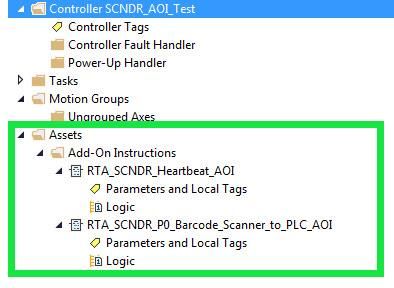
Gateway Configuration
Accessing the Gateways Configuration Pages
Access the browser-based configuration of the 435NBX. By default, DHCP is enabled. If the 435NBX fails
to obtain an IP address over DHCP it will Auto IP with 169.254.X.Y.
    • Connect an 8-24 VDC power source to the gateway, Red Wire = (+) Black Wire = (-).
   •   Using the supplied crossover cable, connect the gateway to the PC.
   •   Insert the provided CD-ROM into a computer also on the network. Refer to the
       Accessing_Browser_Configuration doc to setup DHCP on your PC. This guide is also found on
       https://www.rtautomation.com/wp-content/uploads/Accessing_Browser_Configuration.pdf

   •   Run the IPSetup.exe program from the CD-ROM.

   •   Find unit under “Select a Unit”.

           a. To change the IP Address to match that of your PC if DHCP has failed, enter the desired
              static IP settings on the left-hand side and click Set->.

                    i. You will know DHCP has failed if the gateway’s IP address is AutoIP at
                       169.254.X.Y.
                   ii. If successful it will say DHCP’d at ex: 192.168.0.100 or however your DCHP
                       Client is setup.
   •   Click Launch Webpage. The Main Page should appear.

Real Time Automation®                              9                                     800-249-1612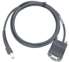
Error: Main Page Does Not Launch
If the Main Page does not launch, please verify the following:

    1. Check that the PC is set for a valid IP Address
           a. Open a MS-DOS Command Prompt
           b. Type “ipconfig” and press enter
           c. Note the PC’s IP Address, Subnet, and Default Gateway
    2. The gateway must be on the same Network/Subnet as the PC whether it’s set up for
       DHCP/Static.

Once you have both devices on the same network, you should be able to ping the gateway using a MS-
DOS Command Prompt.

The screenshot above shows a gateway that is currently set to a static IP Address of 192.168.0.100.

If you can successfully ping your gateway, open a browser and try to view the main page of the gateway
by entering the IP Address of the gateway as the URL.

     Default setting is set to DHCP. If DHCP fails, default IP Address is 169.254.x.y

Real Time Automation®                              10                                     800-249-1612
435NBX Setup
Once you have access to the 435NBX you will have the ability to alter the configuration of the RTA
gateway. Please note: Most settings in the 435NBX are pre-configured for the ScanDr. package. Only the
elements noted below will need to be altered.
Connecting CompactLogix, ControlLogix, Flex I/O
1. Navigate to the PLC Configuration page (orange box).
2. Select your PLC type and enter the IP Address of your Allen-Bradley PLC (green box).
3. Controller Slot is defaulted at 0.
4. Communication Mode is defaulted at Connected Messaging (Class 3 Explicit). Connected Messaging
ensures data is moving as reliably as possible.
Serial Configuration
NO ASCII CONFIGURATION IS REQUIRED The gateway is shipped ready to communicate with the
barcode scanner(s).
ASCII Configuration
NO ASCII CONFIGURATION IS REQUIRED if using a CompactLogix, ControlLogix, or FlexLogix PLC.
Real Time Automation® 11 800-249-1612Connecting MicroLogix, SLC, or PLC5E
1. PLC Configuration:
a. If using a PLC5E, then it must be: Series C, Revision N.1 or later; Series D, Revision E.1 or
later; or Series E, Revision D.1 or later.
b. If using a SLC5/05, then it must be: Series A, Version OS501; or FRN5 Series B and Series
C or later.
2. Navigate to the ASCII Configuration (orange box).
3. Select the Data Type that you defined in the PLC.
4. Enter the File Name that you want to move the ASCII data to.
a. The File must be defined in the PLC and match exactly.
5. Change the Character Count from 4096 to one of the following depending on the Data Type
selected.
a. If using a STRING, set this to be 82
b. If using an INT, the acceptable range is 1 to 200. When using an INT data type, this is the
Character count divided by 2 +1 of the File name. Ex: Character count is 82, in
RSLoigx500 it will be defined as N10:0 with a length of 41. N10:0 will be reserved for the
Length and N10:1…N10:41 will include the data. Clicking the Save Parameters button
will generate an example at the bottom for how to define the PLC (green box).
Real Time Automation® 12 800-249-1612Saving Changes to the Settings
• Any changes made to the IP Address or DHCP settings will take effect immediately.
• All other changes made to the settings of the gateway will not take effect until the gateway is
restarted. Changes will not be stored if the gateway’s power is removed prior to a reboot.
• The gateway detects changes and will prompt you with a red notice box to restart the gateway after
change.
• NOTE: The gateway does not need to be restarted after every change. Multiple changes can be
made before a restart, but they will not be committed until the gateway is restarted.
• When all desired changes have been made, press the Reboot button.
• The webpage will redirect to the rebooting page shown below:
• The reboot can take up to 20 seconds. You will know the save was successful if the red box is no
longer present.
o If the IP Address has not been modified, the gateway will automatically redirect to the
main page.
o If the IP Address was modified, a message will appear at the top of the page to instruct
the user to manually open a new webpage at that new IP.
Fun Fact:
The load screen pays homage to the RCA Television test pattern used from 1939-1970. The Native
American head was used to check brightness and contrast, the corner circles check beam focus on
the edges of the screen, the bars for low frequency response and the large circle to test height.
Real Time Automation® 13 800-249-1612Optional Functionality The RTA gateway supports a heartbeat feature. It can be used to ensure that you still have an active connection to the gateway. This is often used in applications that only execute occasional scans. If the value continues to increment you can be assured of a connection to the PLC. Implement a Heartbeat Using a CompactLogix, ControlLogix, and FlexLogix Optionally, if you want to use a heartbeat tag, use “RTA_SCNDR_Tags.Heartbeat” as your tag name to utilize the RTA_SCNDR_Heartbeat_AOI. The heartbeat tag cyclically updates an INT file in the PLC to let the PLC know that the 435NBX is successfully communicating. Implement a Heartbeat Using a MicroLogix, SLC or PLC5 By default, there is no heartbeat file configured. Optionally, if you want to add a heartbeat file, you will need to create an INT file in the PLC and enter that file name in the 435NBX. The heartbeat file cyclically updates an INT file in the PLC to let the PLC know that the 435NBX is successfully communicating. Real Time Automation® 14 800-249-1612
PLC Programming
AOI Implementation in Studio5000 & RSLogix5000 Programming
The ScanDr. package includes UDTs and AOIs to simplify the integration into RSLogix5000 / Studio5000.
The UDTs and AOIs can be found on the provided CD or can be downloaded
https://www.rtautomation.com/scandr-support/.

Please Note: AOIs and UDTs cannot be used in RSLogix500 or Flex IO.
The instructions below cover the Single and Dual Scanner files.

    1. Scanner .zip files will contain both an optional and required folder.
           a. The optional folder will include:
                     i. Heartbeat AOI, if you choose to monitor the 435NBX
                    ii. SCNDR Sub Routine, this will include all AOIs and UDTs
           b. The required folder will include:
                     i. Port 0 (Single) or Port 0/Port1 (Dual) to PLC AOI
                    ii. New string data type of 4096 characters
                   iii. UDT for Single or Dual Scanner
                   iv. Single or Dual controller tags CSV
    2. Launch RSLogix5000 / Studio5000
    3. Open the Program that will be used for communication to the Real Time Automation 435NBX
       SCNDR package.
    4. Import the Sub Routine
           a. Use this if you want all the files (AOIs and UDTs) loaded listed in 1.a and 1.b.
                     i. Under the “Controller Organizer” (left hand side), right click MainProgram
                    ii. Click Add and select the “Import Routine…” option.
                   iii. Select the “RTA_SCNDR_Single_Sub_Routine.L5X” file. If use using Dual SCNDR,
                        then use the “RTA_SCNDR_Dual_Sub_Routine.L5X.”
                   iv. When the Import screen pops up, select OK
                    v. Create a JSR (Jump to Sub Routine) instruction in the Main Routine that will call
                        the “RTA_SCNDR_Single_Sub_Routine.L5X”. If using Dual SCNDR then use the
                        “RTA_SCNDR_Dual_Sub_Routine.L5X”.

Real Time Automation®                              15                                      800-249-1612
If you don’t wish to use the Sub Routine, follow the instructions below to import the individual AOIs and
UDTs.
5. Import the data types
a. Strings
i. Under the “Controller Organizer” (left hand side), expand the “Data Types”
folder
ii. Right click the “Strings” folder and select “Import String Type…”
iii. Select the “RTA_STRING_4096.L5X” file
iv. Click Import
v. When the import screen pops up, select OK
b. User-Defined
i. Under the “Controller Organizer” (left hand side), expand the “Data Types”
folder
ii. Right click the “User-Defined” folder and select “Import Data Type…”
iii. Select the “RTA_SCNDR_Single_Scanner_UDT.L5X” file, if you have a dual SCNDR
package, then load the “RTA_SCNDR_Dual_Scanner_UDT.L5X”
iv. Click Import
v. When the import screen pops up, select OK
6. Import the Add-On Instructions
a. AOI Port 0 Scanner to PLC
i. Under the “Controller Organizer” (left hand side), right click the “Add-On
Instructions” folder and select “Import Add-On Instruction…”
ii. Select the “RTA_SCNDR_P0_Barcode_Scanner_to_PLC_AOI.L5X”
iii. Click Import
iv. When the import screen pops up, select OK
Real Time Automation® 16 800-249-1612b. AOI Port 1 Scanner to PLC (use only if you have a dual scanner package)
i. Under the “Controller Organizer” (left hand side), right click the “Add-On
Instructions” folder and select “Import Add-On Instruction…”
ii. Select the “RTA_ SCNDR _P1_Barcode_Scanner_to_PLC_AOI.L5X”
iii. Click Import
iv. When the import screen pops up, select OK
c. AOI Heartbeat (Optional)
i. Under the “Controller Organizer” (left hand side, Right Click the “Add-On
Instructions” folder and select “Import Add-On Instruction…”
ii. Select the “RTA_SCNDR_Heartbeat_AOI.L5X”
iii. Click Import
iv. When the import screen pops pp, select OK
7. Import Controller Scope Tags
a. In the tool bar, Select “Tools”
b. Select “Import”
c. Select “Tags and Logic Comments…”
d. Select “RTA_SCNDR_Single-Controller-Tags.CSV” or “RTA_SCNDR_Dual-Controller-
Tags.CSV
Real Time Automation® 17 800-249-16128. Calling an Add-On Instruction
a. The AOI for a single barcode scanner package will display as below:
i. Heartbeat AOI (1st Add-on) and Port 0 (2nd Add-on) will look like this:
b. The AOI for a dual barcode scanner package will display as below:
i. Heartbeat AOI (1st Add-on), Port 0 (2nd Add-on) and Port 1 (3rd Add-on) and
should look like this:
9. Under your Main Program within the Main Routine, you will need to call the AOIs using its
instruction. Below is the breakdown of the arguments.
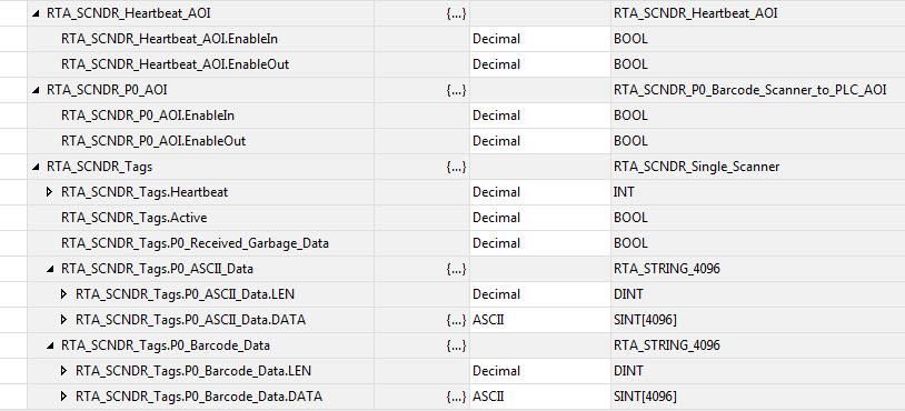
10. If you have Imported the Controller Scope Tags, above 7.a, then the AOI Tags are already set up
for you.
11. In the Ladder Logic that you want to call the AOI from, create an instruction (or new rung) with
the following Add-on.
12. Instruction Name to select:
a. RTA_SCNDR_P0_Barcode_Scanner_to_PLC_AOI: Used for only Port 0
Real Time Automation® 18 800-249-1612b. RTA_SCNDR_P1_Barcode_Scanner_to_PLC_AOI: Used for only Port 1
c. RTA_SCNDR_Heartbeat_AOI: Optional
13. Below is the explanation for all the arguments within an instruction.
a. The first argument is the AOI you set up in 6.a (specific based on the AOI being used)
b. The second argument is the Input Tag (defined as DataIn)
i. For the RTA_SCNDR_P0_Barcode_Scanner_to_PLC_AOI, this is the
Controller Scope Tag that the 435NBX is updating (this is the
“RTA_SCNDR_Tags.P0_ASCII_Data” tag defined in the ASCII to PLC direction of
the 435NBX).
ii. For the RTA_SCNDR_P1_Barcode_Scanner_to_PLC_AOI, this is the
Controller Scope Tag that the 435NBX is updating (this is the
“RTA_SCNDR_Tags.P1_ASCII_Data” tag defined in the ASCII to PLC direction of
the 435NBX).
iii. For the RTA_SCNDR_Heartbeat_AOI, this is “RTA_SCNDR_Tags.Heartbeat”.
14. The third argument is the Output Tag (defined as DataOut)
a. For the RTA_SCNDR_P0_Barcode_Scanner_to_PLC_AOI, this is the Controller Scope
Tag that the AOI is updating for the PLC to process the data (this is
“RTA_SNCDR_Tags.P0_Barcode_Data”)
b. For the RTA_SCNDR_P1_Barcode_Scanner_to_PLC_AOI, this is the Controller Scope
Tag that the AOI is updating for the PLC to process the data (this is
“RTA_SNCDR_Tags.P1_Barcode_Data”)
c. For the RTA_SCNDR_Heartbeat_AOI, this is “RTA_SCNDR_Tags.Active”.
15. The fourth argument is the Garbage Data. This is the received data that was not from a scan of
the barcode.
a. For the RTA_SCNDR_P0_Barcode_Scanner_to_PLC_AOI, this is the Controller Scope
Tag that the AOI is updating for the PLC to know if it received data that was not valid, and it
discarded the data (this is “RTA_SCNDR_Tags.P0_Received_Garbage_Data”)
b. For the RTA_SCNDR_P1_Barcode_Scanner_to_PLC_AOI, this is the Controller Scope
Tag that the AOI is updating for the PLC to know if it received data that was not valid, and it
discarded the data. (this is “RTA_SCNDR_Tags.P1_Received_Garbage_Data”)
Real Time Automation® 19 800-249-1612RSLogix500 Setup
The ScanDr. package does not include UDTs or AOIs for RSLogix500 as it does not support these files.
1. Setting up RSLogix Data Types and Ladder Logic
a. Open RSLogix500
b. Open the Data Files folder and create the file(s) defined in the 435NBX. The file and data type
must match what is set up in the 435NBX.
c. In the Ladder Logic, within a single rung, follow these steps to work with the 435NBX (Example will
reference ST10:0 which is defined in the 435NBX)
a. Not Equal To (NEQ) instruction to check if there is ASCII data to process
i. Source A: ST10:0.LEN
ii. Source B: 0
b. Copy File (COP) instruction to move the ASCII data that the 435NBX is updating to
another file for additional processing
i. Source: ST10:0
ii. Dest: ST11:0 (note: this is a different file for additional processing)
iii. Length: 1
c. Move (MOV) instruction to allow the next ASCII message to be sent from the 435NBX to
the PLC
i. Source: 0
ii. Dest: ST10:0.LEN
Real Time Automation® 20 800-249-1612Setup Is Complete!
Your ScanDr. package is now ready for years of reliable service.
SUPPORT
If at any time you need further assistance do not hesitate to call Real Time Automation support.
Support hours are Monday-Friday 8am-5pm CST
Toll free: 800-249-1612
Email: support@rtautomation.com
Real Time Automation® 21 800-249-1612You can also read