Selection of PCB Materials for 5G - FEBRUARY 2018 - Rogers Corporation
←
→
Page content transcription
If your browser does not render page correctly, please read the page content below

E-BOOK

Selection of PCB Materials
for 5G
                                       FEBRUARY 2018

           S P O N S O R E D   B Y

1                                    MICROWAVE JOURNAL n JUNE 2011
Table of Contents

3              Introduction
Pat Hindle
Microwave Journal, Editor

                                                                                                                                              ENHANCED MOBILE
                                                                                                                                                BROADBAND

4
                                                                                                                                   MASSIVE MACHINE       ULTRA-RELIABLE LOW
                                                                                                                                 TYPE COMMUNICATION   LATENCY COMMUNICATION

             5G: Is it Ready for Take Off?
James Kimery
National Instruments, Austin, Texas
                                                                                                                    RO3003                RO4350B                RO4003C
                                                                                                                    PTFE/WG Dk 3.2        PTFE/WG/Ceramic        FR-4

                                                                                                      1.04

9
                                                                                                      1.03

                                                                       Change from 25°C
                                                                                                      1.02

               Opportunities for High Frequency
                                                                                                      1.01

                                                                                                      1.00

                                                                                                      0.99

               Materials in 5G and the IoT
                                                                                                      0.98

                                                                                                      0.97
                                                                                                         –50          –25         0     25    50      75    100     125     150
                                                                                                                                        Temperature (°C)

Art Aguayo
Rogers Corp., Chandler, Ariz.

13             Paving the Way for 5G Wireless Networks
The ROG Blog is contributed by John Coonrod and various other experts from Rogers
Corporation, providing technical advice and information about RF/microwave materials.

15             Transformation to 5G: PCB Advantage
Tony Mattingly
Rogers Corp., Chandler, Ariz.

                                                                                                                4 Mil LCP Laminate Effective Dielectric Constant vs. Frequency
                                                                                                              for Various Copper Foil Types on 50 Ω Microstrip Transmission Line
                                                                                                             2.8
                                                                                                                                      ED-3.0 µm RMS ED-1.5 µm RMS
                                                                             Effective Dielectric Constant

                                                                                                                                      RT-0.7 µm RMS RT-0.5 µm RMS
                                                                                                             2.7

18
                                                                                                             2.6

                                                                                                             2.5

               Selecting Circuit Material for the                                                            2.4

                                                                                                             2.3

               Different Spectra of 5G Power Amplifiers
                                                                                                             2.2
                                                                                                                0           10          20       30         40         50         60
                                                                                                                                             Frequency (GHz)

John Coonrod
Rogers Corp.

                                             2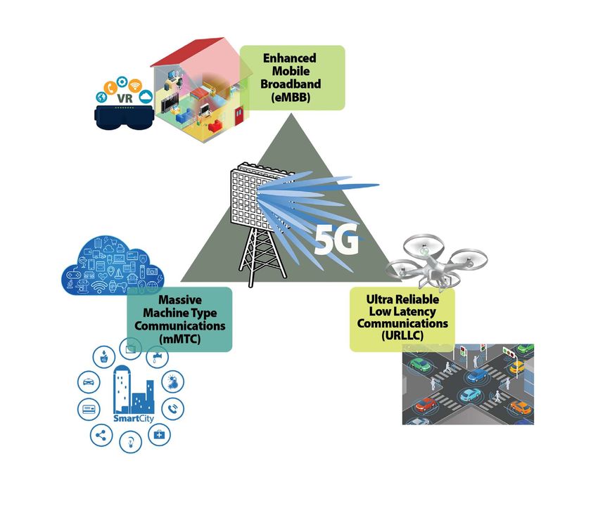
Introduction

                  PCB Materials Considerations for 5G
       With the first 5G NR standard recently approved by the 3GPP at the end of
2017, many companies are racing to design 5G radio products that will demand wider
bandwidths, higher frequencies, enhanced carrier aggregation and support of massive
MIMO.  AT&T and Samsung plan to launch 5G mobile services and Verizon plans to launch
5G Fixed Wireless Access in the US this year while South Korea will be demonstrating  5G at
the upcoming Winter Olympics.
       The demanding performance requirements of 5G will push the limit of PCB designs
from antennas to control functions to amplifier circuits. PCB effects such as copper surface
roughness, Dk variations, thermal dissipation, passive intermodulation, coefficient of
thermal expansion and thickness variations, will affect 5G designs more than previous
generations that had less stringent performance criteria. PCB designers will have to
consider many of these effects in their designs so need to learn about the various tradeoffs
with different types of PCB materials and processes.
       5G mmWave applications will have very different materials needs than sub 6 GHz
applications so these articles also address the requirements for higher frequency designs.
At mmWave frequencies, the effects of small variations in material parameters will have
even more affect on the circuit’s performance. For higher frequencies into the mmWave
range, designers typically need to minimize Dk, copper roughness and thickness variations
as they can all negatively affect performance. These considerations must be incorporated
into the design using accurate models and simulations in order to avoid costly iterations.
       This eBook introduces 5G objectives and goals, opportunities for high frequency
materials in 5G and IoT applications, materials effects for 5G designs, PCB antenna design
considerations, and material selection for the different spectrum of 5G power amplifiers.
The effects of various material parameters on loss, thermal dissipation and reliability are
discussed in these articles to provide designers with the tools needed to account for these
affects.
       Microwave Journal has put together this collection of articles covering these topics.
Rogers Corporation has contributed many of the articles as a leading PCB material
manufacturer offering their expertise and experience in this field to educate designers and
manufacturers about various PCB material considerations in 5G designs.

Pat Hindle, Microwave Journal Editor

                                             3
5G: Is it Ready for Take Off?
James Kimery
National Instruments, Austin, Texas

                      N
                                 ever has there been so much hype      the 3GPP also set key performance metrics
                                 and attention paid to a new wire-     for ultra-reliable low latency communica-
                                 less standard than with 5G. 5G has    tions (URLLC) and increased connectivity,
                                 generated a lot of interest, due to   setting the stage for billions of connected
                      its potential transformational impact on both    devices for massive machine-type communi-
                      consumers and businesses across the globe.       cation (mMTC).
                      Has the hype been overdone? Let’s look at           Today’s wireless standards do not and
                      where we have come from, where we are to-        never have addressed latency and broad
                      day and speculate a bit as to what the future    connectivity. Latency is quite important be-
                      may hold.                                        cause lower latency will not only improve
                                                                       the common data experience for users but
                      HOW WE GOT HERE                                  create new applications that rely on fast
                         A little over 10 years ago, Apple intro-      network response. Low latency and, specifi-
                      duced the iPhone and opened our eyes to          cally, deterministic low latency responsive-
                      the potential of smart devices combined          ness provide the foundation for “control”
                      with wireless broadband data. In 2016, Cisco     applications over the network. Combining
                      published their Global Mobile Traffic Fore-      robots, drones, cars and other devices that
                      cast, estimating that over 1.5 billion smart     “move” with low latency wireless commu-
                      devices were sold globally. The report also      nications makes controlling these devices
                      estimated that by 2021, the world will con-      from a remote location possible, potentially
                      sume over 49 exabytes of data per month
                      —a 7x increase over the usage in 2016. The
                      acceptance, adoption and pervasiveness of
                      smart devices astounds and has been, in                            ENHANCED MOBILE
                      and of itself, transformational. 5G aims to                          BROADBAND
                      go further. Broadband wireless data will con-
                      tinue to draw attention, and the world’s stan-
                      dardization bodies shaping 5G have taken
                      notice.
                         At the outset of the 5G standardization
                                                                              MASSIVE MACHINE       ULTRA-RELIABLE LOW
                      kickoff, the 3GPP outlined three key per-             TYPE COMMUNICATION   LATENCY COMMUNICATION
                      formance metrics (see Figure 1). The 3GPP
                      defined the enhanced mobile broadband
                      (eMBB) use case and attached a perfor-
                      mance target of greater than 10 Gbps peak
                      data rate to expand broadband data servic-
                      es. In response to several industry groups,      s Fig. 1   5G use cases defined by 3GPP.
                                         WWW.MWJOURNAL.COM/ARTICLES/29474
                                                         4
RAN            RAN                                          RAN                           RAN #80
               #74            #75                                          #78                     (Rel-15 Completion)

       2016                                   2017                                                        2018
        Q4               Q1            Q2               Q3         Q4                Q1          Q2              Q3              Q4

              5G Study
                                      5G NR Work Item                   5G NR NSA                  5G NR SA        Further Evolution
                                                                        Completion                Completion

                                                                   Stage 3 Completion          Stage 3 Completion
                                                               for Non-Standalone 5G-NR       for Standalone 5G-NR

                                                                              NSA Option 3 Family ASN-1      Rel-15 ASN-1 for SA & NSA
   NSA = Non-Standalone = EPC Core (”Option 3”) & LTE Anchor
   SA = Standalone

s Fig. 2 Timeline for 5G radio access network standardization. The first NR specification release is scheduled for late 2017, with
updates during 2018.
impacting construction, medicine, manufacturing, re-                    but the shape and structure of 5G NR has been crystal-
tail services and safety. Latency in this context also in-              izing for several months. “Final” solutions will inevitably
cludes delivering timely information from the cloud or                  need some tweaking to meet the standard; however,
deployed sensors to the brains of these devices, so that                progress toward the creation of the ecosystem has al-
decisions can be made on the fly to enhance safety. In                  ready started with a path toward commercialization.
this case, the data is delivered real-time, and the control                 Service operators have announced 5G plans in all
mechanism is deployed on the device.                                    shapes and sizes: SKT and KT are gearing up for 5G
    In 2015, when the 3GPP kicked off the 5G standard-                  trial services to accompany the 2018 PyeongChang
ization effort, the group outlined the timelines and                    Winter Olympics in South Korea. In the U.S., Verizon
key performance objectives for this new standard. The                   has aggressively purchased spectrum in the 28, 37 and
3GPP stated unprecedented guiding principles for the                    39 GHz bands and driven the development of the 5GTF
definition process to follow. First, 3GPP broke compat-                 standard, primarily for fiber to the premises (FTTP) ap-
ibility with prior releases, setting a goal of forward com-             plications. Verizon has been trialing pre-commercial
patibility. By breaking with LTE and prior-generation                   equipment in 11 cities in the U.S. since the beginning
standards, the 3GPP opened a path for innovation to                     of this year and announced plans for initial commercial
meet these very difficult objectives. Second, the 3GPP                  deployments in 2018. T-Mobile, the big winner in this
divided 5G into phases. The first phase, or Phase 1, fo-                year’s FCC auction, won 31 MHz of spectrum around
cused on mobile access below 40 GHz and set a frame-                    600 MHz and announced plans to build a “nationwide”
work for Phase 2 to investigate spectrum above 40 GHz.                  5G network using their newly purchased spectrum.
In all, the 3GPP has been working on 3GPP release 15,                   Sprint has approximately 120 MHz of spectrum in the
also known as 5G New Radio (NR) Phase 1, with an ex-                    2.5 GHz band and has been working with Qualcomm
pected release date of June 2018 (see Figure 2).                        and SoftBank, its parent company, to plan 5G rollouts
                                                                        in 2019. Meanwhile, AT&T has announced plans for IoT
WHERE WE ARE TODAY                                                      services in spectrum it currently owns and acquired Fib-
    As I write this article, the 3GPP is closing in on the first        erTower to obtain licenses at 24 and 39 GHz.
draft of the physical layer of 5G NR Phase 1, targeted for                  Since the 3GPP kicked off the 5G standardization ef-
December 2017. This first draft is critically important, as             fort in 2015, the mMTC use case has been deprioritized.
it establishes the foundation upon which semiconductor,                 The 3GPP continues to evolve LTE; in release 14, the
device, infrastructure, test and measurement and other                  3GPP made several enhancements to LTE specifically
wireless ecosystem players will plan and build their busi-              targeting the mMTC use case, with development of the
nesses. Until this point, the development has evolved us-               NB-IoT and LTE CAT-M standards. The mMTC use case
ing system prototypes for field trails with service operators.          elevates connectivity as a goal, driving device manufac-
With a firmer standard in place, the players can develop                turers to incorporate wireless capabilities into many de-
tangible plans and targets for product and service rollouts.            vices not previously connected, expanding their utility.
    Interestingly, there have been announcements re-                    We have seen a glimpse of the possibilities with new IoT
garding the availability of 5G technologies—specifi-                    devices, but there are significant challenges: there is no
cally by Intel and Qualcomm—and these early develop-                    pervasive or ubiquitous wireless IoT standard. As such,
ments are intended to seed other companies to drive                     there are challenges with interoperability and seamless
adoption. It may seem strange to announce products                      connectivity to infrastructure and smart devices. With
compliant with a standard before the standard is final,                 the 3GPP addressing the mMTC use case in release 14
                                                                   5
and delivering a comprehensive and
widely supported standard, time will                                             TABLE 1
tell whether further enhancements                                      LTE VS. 5G NR PHASE 1
are needed in a future evolution of                                   LTE                              NR Phase 1
5G.
                                          Number of Streams           SISO            SISO per Polarization per Antenna Panel
WHAT WILL 5G LOOK LIKE?                   BW                        20 MHz                               800 MHz
    As noted, the 3GPP plans to final-    Subcarrier Spacing         15 kHz                         240 kHz (Maximum)
ize 5G NR Phase 1, 3GPP Release 15        FFT Size                    2048                              2048, 4096
by the end of 2017, with the ASN.1
                                          Number of Occupied                                       ~1600 (FFT Size 2048)
ratification in June of 2018. The 3GPP    Subcarriers
                                                                      1200
                                                                                                   ~3300 (FFT Size 4096)
has started on the path of defining
the transformational radio access net-    Spectral Occupancy          90%                                  98%
work by including wider bandwidths,       Slot Duration
                                                                      0.5 ms
                                                                                  125 µs [14 Symbols for 120 kHz Subcarrier Spacing]
essential for faster data rates. New                               [7 Symbols]
spectrum has been identified to de-       Antenna                    Omni                         64 Beams (for SS Block)
ploy these wider bandwidth systems.
The 3GPP has also reduced the sym-        NSA and will surely improve data
bol timing compared to LTE, to en-        rates and latency to be much closer                                       EPC
able shorter transfer time intervals      to the 5G targets. The 3GPP is tar-
(see Table 1). In addition, the 3GPP      geting December 2018 to wrap up
has aligned on a self-contained sub-      Phase 1, release 15, which will in-

                                                                                                              UP

                                                                                                                      UP
frame, which enables transmission         clude both NSA and SA.

                                                                                                             CP +
and reception in a single subframe           The 3GPP has accomplished
for time-division duplexing (TDD) sys-    much in a very short time. In the
tems. With this initial work, the 3GPP    short-term, 5G deployments be-
has addressed faster data rates and       low 6 GHz may look a lot like LTE                                       CP + UP
lower latency. Perhaps most impor-        on steroids, i.e., faster data and                                               NR gNB
                                                                                                        LTE eNB
tantly, a new, flexible numerology will   lower latency. The first NSA deploy-
enable operators to accommodate           ments may provide noticeable per-                         Data Flow Aggregation Across
different types of devices and support    formance enhancements over LTE,                           LTE eNB and NR gNB via EPC
diverse use cases.                        and the lightning fast data speeds               (a)
    For mmWave, the 3GPP has iden-        will likely appear when network op-
tified specific frequency bands and       erators deploy mmWave technolo-                                      NextGen Core
incorporated beam management              gies and the new 5G core network,
and control for phased array anten-       needed for SA operation. What is
nas (PAA). Although the stage is set      clear is that this is just the begin-
for mmWave deployments, many              ning. Future evolutions and itera-
practical challenges remain for wide-     tions seem inevitable.
spread adoption (more on this later).                                                                       eLTE eNB
    The 3GPP defined two main net-        CHALLENGES AHEAD
                                                                                                 eLTE eNB Connected to NextGen Core
work architectures for Phase 1. With          As the 3GPP finalizes the formative
                                                                                          (b)
the non-standalone (NSA) architec-        5G specification, the path forward is
ture, the 5G NR uses the existing LTE     not unimpeded. 5G has the poten-
radio access network and evolved          tial to be a “game changer,” but the                             NextGen Core
packet core or EPC (see Figure 3a);       transformational impact must come
NSA includes two additional options       with extensive help from a diverse set
                                                                                                               UP

                                                                                                                          UP

(see Figures 3b and 3c). The second       of players. Potential challenges exist
                                                                                                             CP +

main architecture, named standalone       in three high level areas: mmWave,
(SA), uses the 5G NR and a new 5G         network topology and ecosystem.
core (see Figure 4). NSA enables op-
erators to offer 5G services sooner,      mmWave                                                              CP + UP
taking advantage of the existing in-          The 3GPP chose to incorporate                                               NRgNB
                                                                                                                          NR gNB
frastructure to deliver services in the   mmWave technologies into the                                 eLTE eNB

short-term, since investments for SA      standard due to the scarcity of avail-
                                                                                                 Data Flow Aggregation Across
are expected to be much larger and        able spectrum below 6 GHz. More                   eLTE eNB and NR gNB via NextGen Core
will take more time. In the standards     spectrum equates to faster data                 (c)
meetings, NSA has been a focus be-        speeds. Although the 3GPP will
cause of the immediate opportunity        specify 5G technologies for use in             s Fig. 3   Initial 5G deployments will use
                                          spectrum below 6 GHz, the 3GPP                 the existing LTE radio access network
and, perhaps, a narrower scope. SA                                                       and EPC (a). The NSA specification
will deliver more 5G benefits than        is relying on mmWave, with its copi-           includes architectural options using the
                                                                                         new 5G core (b) and (c).

                                                               6
ous spectrum, to meet its goals for        tically, into the software deployed       3GPP, but the implication was clear.
the eMBB use case. Over the last           on these systems. To support mo-              To describe this flexible network
couple of years, several researchers       bility, the protocol software must        topology, the wireless industry de-
have prototyped mmWave systems             switch the beams in less than 200         fined the term “network slices.”
extensively, but the early prototypes      ns to maintain the link, requiring fast   Network slices describes the ability
were big, bulky and used very new          switching technology in the antenna       of a service operator to “slice” the
technologies such as PAAs.                 assemblies and the software archi-        network to tailor a unique set of ser-
   PAAs overcome the free space            tectures that program them.               vices for users, creating diverse ap-
path loss associated with mmWave               The testing of PAAs and the sys-      plications and use cases and charg-
transmission and reception using           tems that incorporate them is being       ing appropriately for the services.
multiple antenna elements and              investigated and poses new chal-          With network slices, a company or
beamforming to enhance gain.               lenges for the test and measure-          individual could purchase a service
With their benefits, PAAs also pose        ment industry. As PAAs are often          or a set of services to meet specific
system challenges, as the control of       integrated with their transceivers to     needs. For example, consider a
the beams must be incorporated             minimize loss, cable access to these      company that outfits a factory with
into the standard and, more prac-          modules and the arrays that incorpo-      1,000 connected sensors. The com-
                                           rate them will not exist. Over-the-air    pany may expect to pay less than
                                           (OTA) techniques for testing PAAs         $40 per month for unlimited data,
                NextGen Core
                                           are being explored by several com-        since those sensors do not transmit
                                           panies, with proposals submitted          or receive the type of data that we
                                           to the 3GPP RAN4 working group            consume on our smartphones.
                                           for incorporation into the standard.          While the 3GPP has, indeed,
                                           OTA introduces new variables to the       made great progress toward de-
                                           test equation; most significant is the    fining a radio access network ca-
                                           need to minimize test time and test       pable of achieving these lofty goals,
                                           cost. Test and measurement compa-         network operators must be able
               NR gNB
                                           nies must deliver fast, cost-effective    to fairly charge for these services
       NR gNB Connected to NextGen Core
                                           solutions to the wireless industry to     and conserve valuable network re-
 (a)                                       facilitate the development of the         sources to sustain a healthy ecosys-
                                           mmWave ecosystem.                         tem and enable all contributors to
                                               Even with PAAs in both the user       prosper. To facilitate the creation
                NextGen Core               equipment (UE) and infrastructure         of network slices, the 3GPP has en-
                                           (i.e., gNodeB), mmWave propaga-           hanced the split architecture of the
                                           tion is limited, even at the lower        control and user planes to enable
                     P
                    +U

                                           mmWave frequencies. Denser de-            separate control and data paths.
                          UP

                                           ployment of the infrastructure is a       This is just the foundation. Network
                 CP

                                           foregone conclusion that will likely      slicing also depends on implement-
                                           signal more costly rollouts of the        ing infrastructure elements beyond
                     CP + UP               technology and systems. To ad-            the physical layer of the protocol
                           eLTE eNB        dress the density challenge, re-          stack. Network technologies such
            NR gNB                         searchers are exploring new tech-         as virtual EPC, network function vir-
                                           niques for mesh and integrated            tualization (NFV), software defined
        Data Flow Aggregation Across
    NR gNB and eLTE eNB via NextGen Core   access backhaul (IAB) to minimize         networking (SDN) and mobile edge
 (b)                                       the cost of denser deployments            computing (MEC) are components
                                           by utilizing the 5G gNodeBs al-           and services necessary to move net-
                                           ready deployed. IAB would reduce          work slicing forward. Without these
                NextGen Core
                                           the cost of running fiber to each         technologies, all data and control
                                           mmWave access device; however,            traffic must aggregate at the core
                     P

                                           the technique may introduce more          network, potentially crippling the in-
                         UP
                    +U

                                           latency.                                  dustry’s ability to meet the goals of
                 CP

                                                                                     data throughput, end to end (E2E)
                                           Network Slicing
                                                                                     latency and massive connectivity.
                                              One of the more impactful ob-
                     CP + UP
                                           servations for 5G transformation is       Creating the Ecosystem
                           NRgNB
                           NR gNB
           NR gNB                          that the networks must morph and              5G’s success or failure will de-
                                           scale to optimize resources to sup-       pend on the creation of an eco-
         Data Flow Aggregation Across      port new applications and services.       system. The 5G ecosystem must
          NR gNBs via NextGen Core
 (c)                                       “Scalable” networks was not an ex-        extend beyond the traditional
                                           plicit goal outlined by the ITU or the    wireless value chain of usual par-
s Fig. 4  The SA specification assumes
                                           Next Generation Mobile Networks           ticipants: the service providers,
the 5G NR and a new 5G core (a),
with two additional options to handle      (NGMN) Alliance when the 5G stan-         semiconductor companies, infra-
deployment scenarios (b) and (c).          dardization process was kicked off by     structure manufacturers and test

                                                             7
and measurement companies, to          Markit is not alone in their predic-   ership, 5G has unstoppable mo-
name a few. Application software       tion, as the world’s economic lead-    mentum.
and service providers, cloud and       ers continue to invest in 5G with a        The industry has made great
cloud infrastructure, vertical inte-   myriad of funding and regulatory       strides in moving the 5G agenda
grators, software companies and        support. These global leaders are      forward, achieving key milestones
even car, drone, appliance, medi-      betting on 5G to catalyze GDP          in both the standardization process
cal device and construction manu-      growth and create economic pros-       and technology development. De-
facturers must be an integral part     perity. While 2035 is 20 years away,   monstrable commitments from aca-
of the 5G landscape to realize the     the 5G foundation is being laid        demia, industry and governments
true economic potential. Creating      today. Creating an ecosystem for       worldwide have created forward
an ecosystem does not occur over-      these applications will take invest-   momentum, yet there remains much
night. The initial deployments of      ment, dedication and perseverance      to do. 5G below 6 GHz may have
5G services to enable the ecosys-      and, above all, time. The various      a shorter runway to deployment,
tem to grow and evolve are critical.   ecosystem players must step up to      but mmWave is very important to
                                       the plate to realize the vast poten-   the overall 5G vision. The next year
A 5G FUTURE                            tial that 5G promises.                 should provide a better picture of
   Qualcomm recently commis-               As noted, initial rollouts are     the 5G timelines and potential, and
sioned a study by IHS Market to        scheduled for next year, and more      the world will be watching the prog-
assess the economic impact of 5G.      meaningful deployments will begin      ress on the challenges outlined in
IHS Markit speculates that 5G will     in 2019. To realize 5G’s potential,    this article. The major players have
become a general purpose tech-         significant innovations must occur     all anted up, but there are real and
nology (GPT), a development so         in semiconductors and packaging        hard problems to solve for 5G to
impactful that it becomes a catalyst   technology, system and network         live up to its promise. 2018 should
for socio-economic transformation.     topologies and architectures and,      be an interesting year and this time
For perspective, other examples in     of course, the important verticals     next year, a clearer picture of the fu-
our history cited as GPTs include      that will take advantage of this new   ture should materialize.
the printing press and electricity.    network of 5G capabilities and ser-        The central question is not
IHS Markit expects 5G to contribute    vices. It will not be easy, but with   whether 5G will be impactful, the
$12.3 trillion—yes, that is a “t”—to   the commitment of the industry         question is when?■
the global economy by 2035. IHS        and the world’s government lead-

                                                        8
Opportunities for High
Frequency Materials in 5G
and the IoT
Art Aguayo
Rogers Corp., Chandler, Ariz.

                                                                                                N
                                  Enhanced Mobile Broadband                                                 ot a day goes by that we don’t
                                                                                                            encounter the terms 5G and IoT
                   Gigabytes in a Second                                                                    (Internet of Things). Indeed, the
                                                                   3D Video, UHD Screens
                                                                                                            future is about super-connectivity
                                                                   Work and Play in the Cloud   and the promise it gives us, once everything
             Smart Home/Building                                     Augmented Reality
                                                                                                is “talking” with each other. Connected
                                                                         Industry Automation    appliances to connected cars, making life
                          Voice
                                                                         Mission Critical       easier as we prepare for smart homes, smart
             Smart City                         Future IMT
                                                                          Application           cities and smart everything. It is difficult to
                                                                            Self Driving Car    imagine this future—yet so was imagining
                                                                                                2015 when looking through the view of the
             Massive Machine Type                 Ultra-Reliable and Low Latency                internet in the year 2000.
               Communications                            Communications
                                                                                                    There appear to be as many definitions
             (a)                                                                                of 5G and IoT as forecasts and opinions
                                                                                                when discussing the potential benefits and
               Peak Data Rate (Gbps)                  User Experienced Data Rate (Mbps)
                                                                                                relevant business cases of these technolo-
                                       20                    100                                gies. The International Telecommunication
                                            IMT-2020
                                                        10                                      Union (ITU) has been working on defining
               Area Traffic
                                            1
                                                                       Spectrum Efficiency
                                                                                                what 5G IMT-2020 will be from a technical
                 Capacity 10                                                                    perspective, or at least how it will differ in
                (Mbps/m)          1                                1× 3×
                                      0.1                                                       performance from 4G (IMT-Advanced). The
                                      1×                     350                                term 5G IMT-2020 was coined in 2012 by
                          100× 10×                              400
                                                                       500                      the ITU Radiocommunication sector and
             Network Energy               IMT-Advanced                       Mobility (km/h)    means “international mobile telecom-
                Efficiency              105         10                                          munication system,” with a target date of
                                      106              1                                        2020. Within that definition, we see how
             Connection Density (Devices/km2)           Latency (ms)                            IoT will benefit. Parameters like peak data
                                                                                                rates, mobility, latency and spectrum ef-
             (b)
                                                                                                ficiency are important, as they help define
            s Fig. 1 ITU vision for IMT-2020, including usage scenarios (a)                     what the user experience will be, key to
            and enhancement of capabilities from IMT-Advanced (b).                              enhanced mobile broadband (eMBB) and
                                                                                                ultra-reliable and low latency communica-
                                                                                                tions (URLCC). Figure 1 shows how the ITU
                                                                                                envisions 5G.
                                                                                                    IoT, on the other hand, will need different
                                                                                                parameters to operate in a way that needs
                                                        WWW.MWJOURNAL.COM/ARTICLES/27688
                                                                                   9
in Figure 3). The focus of these ma-
                                                      TABLE 1                                                  terials has been low cost and ease
                                                 IoT APPLICATIONS                                              of manufacturing for complex multi-
                   IoT Category                              Example Applications                              layer boards, with no real attention
                                                                                                               on repeatability of electrical proper-
                   Massive IoT               Smart Building, Transport Logistics, Fleet Management,
                                                           Smart Meters, Agriculture
                                                                                                               ties, since the applications where
                                                                                                               these are used don’t require that
                    Critical IoT           Traffic Safety, Autonomous Vehicles, Industrial Applications,       level of performance. The second
                                              Remote Manufacturing, Healthcare (including Remote
                                                                    Surgery)                                   set of materials use specialty resins,
                                                                                                               sometimes blended with epoxy, and
                                                           Because much of 5G will be data                     achieve some improvement in loss.
                                                           intensive, the frequencies around                   These materials have mainly been
                                                           28, 39 and 77 GHz are gaining mo-                   used in high speed digital applica-
               Fixed Phone         Mobile Phone            mentum because of the availability                  tions up to 10 Gbps. The last group
               PC/Laptop/Tablet    Non-Cellular IoT
               Cellular IoT                                of spectrum within those bands. As                  is defined as high frequency mate-
              30                                           many IoT applications are expected                  rial (found in tiers 5 and 6), where
              25                                           to be low data rate, most of the IoT                the Df is less than 0.005.
 (Billions)

              20
              15
                                                           activity is centering on the sub-6                      Various parameters are consid-
              10                                           GHz spectrum. An exception will                     ered in the selection process when
               5                                           be IoT for surveillance, where trans-               deciding which type of PCB mate-
               0
                       2015               2021             mitting high definition video from                  rial to use: loss, dielectric constant,
                                                           remote areas may require the band-                  thickness, thermal conductivity and,
                                                           width found in the millimeter wave                  let’s not forget, cost. In the end, it is
s Fig. 2 Connected devices forecast,                       spectrum.                                           about selecting the appropriate ma-
from 2016 Ericsson Mobility Report.                                                                            terial at the right cost. Much of the
minimal to no user action on a day-                        MATERIALS PERSPECTIVE                               IoT market today is using traditional
to-day basis, after the initial setup.                         Printed circuit boards (PCB) are                FR-4 in the transceiver or antenna
Today, we are seeing the beginning                         a building block in any electronic                  portions of the radio. However,
of the IoT market, an expansion of                         system. The choice of PCB mate-                     there is a subset of this market that
the M2M market that already ex-                            rial for RF applications depends                    requires a higher level of reliability,
ists and accounts for 600 million                          on frequency, power level, circuit                  including industrial, medical, traffic
devices as of 2015.1 The IoT can                           size and function. Designers have                   control, automotive and smart me-
be divided into two segments.2 The                         choices from basic epoxy/glass                      ters. This subset is taking advantage
first represents massive IoT connec-                       materials (FR-4), mid-loss materi-                  of the higher performance materials
tions with high connection volume,                         als and, ultimately, high end mi-                   and the increased focus on reliabil-
low cost, low energy consumption                           crowave/millimeter wave materials.                  ity that tier 5 and 6 materials can
and small data traffic. The second                         The most common PCB material                        provide.
comprises critical IoT connections                         is FR-4, mainly developed for the                       So what are the benefits of se-
that require ultra-reliability and                         mechanical properties key to mul-                   lecting a high performance mate-
availability with very low latency.                        tilayer circuit boards. Variations of               rial instead of FR-4? The first ben-
Table 1 shows applications for each                        these materials exist, offering dis-                efit a designer will notice is the
of the two classifications. Figure 2                       sipation factor (Df) or loss tangent                impact loss tangent has on the
shows a forecast for the connected                         values ranging from 0.01 to beyond                  loss of the circuit. Many times, this
devices market, based on Ericsson’s                        0.02 (see the tier 1 and 2 materials                is the primary consideration. This
mobility report.3 The traditional
connected-device market of fixed,                                                                   TABLE 2
mobile phones and computer/                                                               LOW POWER IoT STANDARDS4
tablets will increase slightly, while
                                                                              Bluetooth,          NB-IoT          EC-GPRS        SigFox        LoRa
the overall number of devices as-                                             Wi-fi, RFID,
sociated with IoT, both cellular and                                           ZigBee,
non-cellular, will grow greater than                                           Z-Wave
20 percent annually. The IoT space                              Range       10 cm to 200 m        < 11 km         < 11 km        < 9 km       < 7 km
can also be viewed by how connec-
                                                              Maximum            < 100              164             164           160           157
tivity is achieved, particularly using                        Coupling
low power technology. Various low                             Loss (dB)
power standards are summarized in                             Spectrum,       Unlicensed       Licensed IMT,      Licensed     Unlicensed   Unlicensed
Table 2.                                                      Bandwidth        2.4 GHz            200 kHz        800 to 900     868 MHz,     868 MHz,
    Frequency band allocations for                                                                Shared        MHz, Shared      600 Hz       125 kHz
5G focus heavily on available band-
width, and they seem to center
around three groups: sub 6 GHz, 15                            Data Rate       < 100 Mbps       < 62 kbps UL
tivity and will extend the range of higher than with the more stable
the antenna. materials in the figure. FR-4 can
In some cases, it is not the loss of change as much as 400 ppm/°C.
the material that is the main driver With materials like RO3003™ and
for selecting a high performance RO4350B™ laminate, the short-
Tier
6 Df < 0.002 material; sometimes it is the variabil- term change is close to 40 ppm/°C.
Tier 5 Df = 0.002 to 0.005
ity of the dielectric constant. Most Considering all these factors (i.e.,
high performance materials have a tolerance, moisture absorption and
Tier 4 Df = 0.005 to 0.008
tolerance of less than ±2 percent, temperature variation), selecting a
Tier 3 Df = 0.008 to 0.01 even less for materials with low di- high frequency material over FR-4
electric constant, while FR-4 materi- may be the best choice when a
Tier 2 Df = 0.01 to 0.02
als can be greater than ±5 percent. more consistent design is needed
Df > 0.02 The increased variability of the FR-4 in the field.
Tier 1
may require the circuits to be tuned In many cases, the IoT will be
to ensure they operate within the about having connectivity with a cir-
frequency specified, while materials cuit as small as possible, due to lim-
with tighter tolerance will not need ited space. In these cases, reducing
such optimization. the size of the antenna or circuit will
s Fig. 3 PCB material classification by Environmental changes can af- be desired. By selecting materials
loss tangent (Df). fect the dielectric constant of FR-4, with a dielectric constant of 6, 10 or
difference can be almost an order yet have minimal impact on high higher, designs using FR-4 with a Dk
of magnitude greater with some performance materials. FR-4 has of 4.4 can be reduced in size. Using
materials. To keep it simple — and significantly higher moisture ab- a PCB with a Dk of 4.4, the wave-
not include in the analysis the im- sorption than high performance length at 1 GHz for 0.020” microstrip
pact dielectric constant has as Dk materials. This leads to an increase is about 7”, while a material with a
of FR-4 is 4.4 and many high fre- in Dk (also Df). If the circuit needs Dk of 10.2 (e.g., Rogers RO3010™
quency materials options are low- to operate in a high moisture en- laminate), the wavelength is 4.4”,
er — consider the simulated in- vironment—tropical areas such close to a 40 percent reduction in
sertion loss for a 50 Ω transmission as Malaysia—FR-4 materials have size.5 Higher dielectric constant ma-
line on FR-4, with Dk = 4.4 and been known to drift, due to the terials allow designers to shrink the
a dielectric thickness of 0.020”. change in dielectric constant. In size of the circuit board, saving area
The 50 Ω width is calculated to be comparison, moisture has minimal compared to FR-4.
0.038”.5 Comparing the change in impact on the dielectric constant There will also be IoT applica-
insertion loss when Df varies from of the high frequency laminates. tions that operate at higher fre-
0.02 to 0.004 at 2.4 GHz for this Changes in the temperature can quencies, potentially in the 28 to
line width, the insertion loss is 0.24 also have a significant impact on 40 GHz range, and not necessarily
dB/inch for a Df of 0.02; for a Df the operation of a circuit: with on low power networks where the
of 0.004 the insertion loss will only FR-4, notably, dielectric constant use of high frequency materials is a
be 0.01 dB/inch. The benefit here changes with temperature (see must. Managing losses is extremely
is that if the circuit is an antenna, Figure 4). The change with FR-4 important, so using materials with
the lower loss improves the sensi- is close to an order-of-magnitude low dissipation factors is critical, as
well as selecting copper foils that
are smooth, to reduce the conduc-
tor impact on insertion loss. In the
case of materials based on PTFE
RO3003 RO4350B RO4003C
PTFE/WG Dk 3.2 PTFE/WG/Ceramic FR-4 resin, this is often addressed by
using rolled copper foil instead of
1.04 traditional electrodeposited cop-
1.03 per foil. However, for materials that
use low loss thermoset resins, us-
Change from 25°C
1.02
ing smooth foil impacts copper
1.01 peel strength, in many cases lower-
1.00 ing the value to the limit specified
by the industry. To address this,
0.99
Rogers introduced LoPro® copper
0.98 foil to go with Rogers RO4000®
0.97
materials, allowing designers to re-
–50 –25 0 25 50 75 100 125 150 duce insertion loss while maintain-
Temperature (°C) ing copper foil peel strength to the
level of standard copper.
s Fig. 4 Normalized dielectric constant vs. temperature.
11References
CONCLUSION driving are topics of much interest. 1. Cisco, “Visual Network Index: Global
5G and IoT have moved from if Many of these may benefit by us- Mobile Data Traffic Forecast Update,
they happen to when they happen. 2015-2020,” February 2016.
ing higher performance materials, 2. International Communications Union,
It is likely that the applications that especially for applications that use “IMT Vision–Framework and Overall Ob-
will revolutionize our lives may not millimeter wave frequency bands. jectives of the Future Development of
yet have been thought of. What we Much is yet to be defined about 5G IMT for 2020 and Beyond,” September
do know is that many segments in 2015.
and IoT, and we will no doubt see 3. Ericsson, “Ericsson Mobility Report,”
the market will be undergoing sig- surprising use cases emerge. When June 2016.
nificant change during the next few asked, “Why did we connect a par- 4. Nokia, “From NB-IoT to 5G,” IWPC
years. Smart homes, smart cities, ticular thing to the internet,” we Workshop Presentation, October 2016.
remote health care monitoring, in- may find ourselves saying “because 5. Simulation Using Rogers’ Microwave
dustrial controls and autonomous Impedance Calculator, www.globalcom-
we could.”■ mhost.com/rogers/acs/techsupporthub/
en/calculator.php.
Microwave Impedance Calculator
This software is intended to assist with microwave circuit design in
predicting the impedance of a circuit made with Rogers High Fre-
quency circuit materials. The software also has some capabilities for
predicting transmission line losses as well. The user will select the cir-
cuit materials and the circuit construction, after which the software will
determine the predicted impedance and other electrical information.
The calculator uses well known closed form equations to determine
impedance and loss of a given circuit model. The loss calculation is
divided into conductor loss and dielectric loss. With specific circuit
designs, the calculator also predicts other properties such as wave-
length in the circuit, skin depth and thermal rise above ambient.
Free (Requires Registration)
https://youtu.be/F_AeAUk7DuU
12Paving the Way for 5G Wireless
Networks
The ROG Blog is contributed by John Coonrod and various other experts from Rogers
Corporation, providing technical advice and information about RF/microwave materials.
G
rowing demand for mobile wire- search experiments, but 5G represents an
less communications services has opportunity to “popularize” millimeter-wave
quickly eclipsed the capabilities of frequencies and make them part of everyday
Fourth Generation (4G) Long Term life, not just for exotic electronic devices in
Evolution (LTE) wireless networks and cre- the limited quantities used in research and
ated a need for a next-generation mobile by the military, but for potentially billions of
wireless network solution. Fifth Generation electronic devices for people and things, as
(5G) wireless networks promise more capac- in how Internet of Things (IoT) devices will
ity and capability than 4G LTE systems, us- use 5G networks for Internet access.
ing wider channel bandwidths, new antenna Designing circuits at millimeter-wave fre-
and modulation technologies, and higher quencies starts with the right PCB material,
carrier frequencies even through millimeter- and knowing how different PCB characteris-
wave frequencies. But before 5G wireless tics affect circuit performance at millimeter-
networks can become a reality, systems and wave frequencies. Variations in certain cir-
circuits will be needed for higher frequen- cuit material parameters, such as dielectric
cies than current 2.6-GHz 4G LTE wireless constant (Dk), can have greater impact on
networks. performance as the operating frequency in-
Standards are still being formulated for creases. For example, signal power is a valu-
5G wireless networks, with goals of achiev- able commodity at millimeter-wave frequen-
ing data rates of 10 Gb/s and beyond with cies, requiring circuit designers to minimize
low latency, using higher frequencies than loss in their circuits as much as possible.
in traditional wireless communications sys- This begins with the choice of PCB material,
tems. In the United States, for example, last since a PCB material not meant for use at
year the Federal Communications Commis- millimeter-wave frequencies can result in ex-
sion (FCC) approved the use of frequency cessive signal losses when operated beyond
bands at 28, 37, and 39 GHz for 5G. its intended operating frequency range.
PCB materials can degrade signal power
PCB MATERIALS FOR MILLIMETER in three ways: radiation losses, dielectric loss-
WAVES es, and conductor losses. Losses through ra-
For circuit designers, one challenge will diation of EM energy largely depend on the
be in knowing where to start, which means, circuit architecture, so even the lowest-loss
for millimeter-wave frequencies, knowing PCB material may not save a circuit configu-
what types of printed-circuit-board (PCB) ration that has a tendency to radiate energy.
material characteristics are the most impor- A thoughtful choice of PCB material can
tant at higher frequencies. Millimeter-wave help minimize dielectric and conductor loss-
frequencies (above 30 GHz) were once used es at millimeter-wave frequencies. A circuit
almost exclusively by the military and for re- material’s dielectric loss is closely related
13to its dissipation factor (Df) or loss effects of copper surface rough- be maintained in climate-controlled
tangent, which increases with fre- ness on loss become apparent at environments, circuits may be sub-
quency. The Df is also related to a millimeter-wave frequencies. For ex- ject to changing environmental
material’s dielectric constant (Dk), ample, two circuits based on 5-mil- conditions, such as high relative
with materials that have higher val- thick RT/duroid® 6002 circuit mate- humidity (RH). Water absorption
ues of Dk often have higher Df loss, rial from Rogers Corp. but with two can dramatically increase the loss
although there are exceptions. At- different types of copper conductor of a PCB material, and the loss of
tempts to minimize dielectric losses and surface roughnesses were test- circuit materials with high moisture
for millimeter-wave circuits can be ed at 77 GHz. The circuit with rolled absorption will be greatly affected
aided by considering circuit materi- copper and root mean square (RMS) under high RH conditions.
als with low Df values. conductor surface roughness of 0.3 Testing on 5-mil-thick RO3003™
μm exhibited considerably lower circuit material from Rogers Corp.
CONTROLLING CONDUCTOR conductor loss than the same circuit for two different operating environ-
LOSS material with electrodeposited (ED) ments showed how loss at millime-
Finding a material with low con- copper conductor having 1.8-μm ter-wave frequencies can increase
ductor losses at millimeter-wave fre- surface roughness. with RH. One circuit was maintained
quencies is not as straightforward, Propagation of the small wave- at room temperature and the other
since conductor losses are deter- lengths at millimeter-wave frequen- was subjected to +85ºC and 85%
mined by a number of variables, cies can also be affected by the RH for 72 hours. At 79 GHz, the
including the surface roughness type of finish used on a PCB’s con- room temperature material had
and the type of finish. As the name ductors. Most plated finishes have about 0.1 dB/in. less loss than the
suggests, millimeter-wave signals lower conductivity than copper, and material subjected to higher humid-
have extremely small wavelengths, their addition to a copper conductor ity and temperature. When testing
mechanical variations in a circuit- will increase the loss of the conduc- was performed on a third, thermo-
board material can have significant tor, with loss increasing as the fre- set circuit material from a different
effects on small-wavelength signals. quency increases. Electroless nickel supplier, the increase in circuit loss
Increased copper surface roughness immersion gold (ENIG) is a popular at 79 GHz was even more dramatic.
will increase the loss of a conductor, finish for copper conductors; unfor- For those interested in learning
such as a microstrip transmission tunately, nickel has about one-third more about the nuances of select-
line, and slow the phase velocity of the conductivity of copper. As a re- ing PCB materials and designing
signals propagating through it. In sult, ENIG plating will increase the circuits for 5G, in particular at milli-
microstrip, signals propagate along loss of a copper conductor, with the meter-wave frequencies, Rogers has
the conductor, through the dielec- amount of loss increasing as a func- created a number of tutorial videos
tric material, and through the air tion of increasing frequency. in their “The Road to 5G” series.
around the circuit material, so the The videos guide viewers on what
roughness of the conductor at the ENVIRONMENTAL EFFECTS different circuit material parameters
interface with the dielectric mate- Environmental conditions can mean at millimeter-wave frequen-
rial will contribute to the conductor also impact the amount of loss ex- cies, and which material character-
loss. The amount of loss depends hibited by a PCB material, especial- istics make the most difference at
on frequency: the loss is greatest ly at millimeter-wave frequencies. those higher frequencies. The vid-
when the skin depth of the propa- Many network scenarios for 5G pre- eos offer quick and easy ways to
gating signal is less than the copper dict the need for many smaller wire- learn how to specify PCB materials
surface roughness. Such a condition less base stations than used in ear- for 5G, and to get ready for this next
also degrades the phase response lier wireless network generations, revolution in wireless communica-
of the propagating signal. in part because of an increased tions.
The impact of copper surface number of expected users and the Do you have a design or fabrica-
roughness on conductor loss de- use of millimeter-wave frequencies tion question? Rogers Corporation’s
pends on the thickness of the PCB and their shorter propagation dis- experts are available to help. Log in
material: thinner circuits are more tances than lower-frequency carri- to the Rogers Technology Support
affected than thicker circuits. The ers. Where 5G base stations cannot Hub and “Ask an Engineer” today.
14Transformation to 5G:
PCB Advantage
Tony Mattingly
Rogers Corp., Chandler, Ariz.
H
ard to believe it has been an hour a day of mobile video at 1
over 30 years since 1G Mbps throughput—which is typical
was introduced to the of applications supporting stream-
world, back when there ing video like YouTube or Netflix—
were no official requirements and consumes 13.5 GB per month. The
analog technology was being used. demand for data will continue to
The 1990s brought 2G, with the grow as the 5G and IoT ecosystems
introduction of digital technology are created in the coming years (see
and the ability to transmit text mes- Figure 1), and we will all eventu-
sages via your cellular device. Ten ally live in a world that depends on
years later, in 2000, an upgrade to billions of devices communicating
3G brought IEEE WiMAX standards with one another. The connectivity
that were designed to support 30 of these devices will be expected to
to 40 megabit per second (Mbps) be instantaneous and without inter-
data rates. Then, 4G was intro- ruption.
duced a mere seven years ago and, Adding capacity is not cheap,
although it brought to the world and space for additional antenna
a much higher spectral efficiency, towers is limited. In the U.S., most
exponential consumer demand towers are not owned by carriers,
for wireless data is now driving a rather companies such as American
need for substantially higher mo- Tower, Crown Castle and SBA. Car-
bile network capacity and perfor- riers lease space on these towers
mance. Let’s take, for example, the and, as strict permitting processes
primary driver for data usage on make it difficult to build new sites,
smartphones: video streaming. Just carriers are forced to replace anten-
nas with newer and more efficient
ones. Arguably, the cost for opera-
tors to deliver data is proportional
to the spectral efficiency of the
wireless technology. LTE networks
have the highest spectral efficiency
of any technology to date, but it is
not going to be enough to serve
consumer desire to always be con-
nected. So how is capacity added
in an already saturated wireless
infrastructure? One answer is ad-
vanced antenna designs employ-
ing new technologies that operate
within current frequencies. Another
answer is adding wireless infra-
structure that operates at new and
higher frequencies, where plenty of
s Fig. 1 Our world is increasingly connected, which is driving spectrum exists. Early in 2015, U.S.
the growing demand for wireless data. carriers spent more than $40 billion
WWW.MWJOURNAL.COM/ARTICLES/28308
15EMBB • Personalized Broadcasting
Enhanced • Fixed Broadcasting
Mobile to Home, GB High User
Broadband • Augmented Reality Peak Data Importance Experienced
EMBB Rate Data Rate
Medium
Area Spectrum
Traffic Capacity Low Efficiency
• Connected Car Network
• Home IoT MMTC URLLC • Remote Surgery Energy Efficiency Mobility
• Smart City Massive Machine-Type Ultra-Reliable • Remote Control
• Smart Grid Communications Low Latency (Drone, Robot)
MMTC URLLC
Connection Latency
Density
(a) (b)
s Fig. 2 5G is envisioned to support three general use cases: high data rate, low latency and massive numbers of connections (a),
and these use cases define the performance requirements of the network (b).
on spectrum! Because much of the spectrum below 2.5 high data rates. While millimeter wave frequencies suffer
GHz is limited, frequency bands around 3.5, 28, 39 and from characteristics such as higher propagation loss—
77 GHz are gaining interest because of the availability even with line-of-sight conditions and no obstructions—
of bandwidth. this challenge can be overcome with beamforming an-
tenna arrays or massive MIMO.
5G COMING SOON Regulatory policies around the world are striving to
We should start by clarifying the conceptual goals keep pace with these changing technologies. Some
for 5G (see Figure 2). Cost to deliver data is crucial to of the complex issues to be addressed: allocating and
the success and survivability of the carriers, so the 5G managing the new spectrum, maintaining neutrality
infrastructure will need to support a greater number of within the networks and preserving privacy. Spectrum
devices at lower average revenue than with 4G systems. is considered a precious commodity within the industry.
The infrastructure must also provide peak data rates of This could be seen during the U.S. auction for the 3.5
multi-gigabits per second (Gbps), facilitate a user expe- GHz small cell band last year, spectrum the FCC is now
rience that is uniform throughout the coverage area— enabling. As advancements in technology provide a
no matter the device density—support numerous fre- path for small cell operation between 6 and 100 GHz, a
quencies (including cellular bands and frequencies vast amount of available spectrum is introduced. Wider
above 6 GHz), use both licensed and unlicensed bands radio channels operating at higher frequencies enable
and follow advanced spectrum sharing rules. much higher data rates. Small cells offload data from
The 5G networks of the future will require infrastruc- macro cells, inherently increasing capacity, and can of-
ture that has a wide range of capabilities and operates fer improved signal quality in places with a higher con-
both below 6 GHz and at millimeter wave frequencies. centration of users or where the signal from a macro
These networks will use massive MIMO antenna struc- tower is weak. Millions of small cells will eventually be
tures and massive carrier aggregation and will need to deployed, leading to massive increases in capacity. The
operate “lightning fast” with very low latency. Massive industry is slowly overcoming challenges that have im-
MIMO comprises hundreds of antennas at the base sta- peded small cell deployments. These include govern-
tion that enables spatial multiplexing and beamforming. ment regulations, acquiring real estate for the antennas
These systems provide three times the spectral efficiency and managing and preventing interference. Another
of today’s LTE-Advanced antennas. Carrier aggrega- challenge relates to spectrum sharing. Future wireless
tion, which is a key LTE-Advanced feature that operators systems may interface with a planned spectrum access
are deploying globally, uses spectrum more effectively, system that manages spectrum among primary users—
increases network capacity and user throughput rates government agencies, in some cases—and secondary
and provide new ways to integrate unlicensed spec- or tertiary users. This will enable more efficient use of
trum. Frequency band allocations for 5G focus heavily spectrum for scenarios in which incumbents use spec-
on bandwidth availability and seem to center around trum lightly.
three groups: below 6 GHz, 15 to 40 GHz and above 60 Many countries have started 5G trials, focusing on
GHz. The combination of lower and higher frequencies various applications and using different frequencies. Ma-
is crucial for 5G operation. Lower bands can be devoted jor carriers in the U.S. are conducting trials in 2017 with a
to coverage and control, while the higher bands enable focus on fixed broadband at 28 GHz. South Korea is also
16conducting trials at 28 GHz to pre- of wireless infrastructure. These de- ed using a patented LoPro copper
pare for the 2018 Olympic Games signers need to overcome the many foil, and it incorporates low density
in Seoul. Japan plans to start trials challenges and understand what microspheres, yielding a laminate
in Tokyo during 2017, using both performance properties are needed that is 30 percent lighter than PTFE
sub-6 GHz and 28 GHz, and they to meet their design goals. materials. The coefficient of ther-
will likely scale up the trials signifi- With the use of additional fre- mal expansion (CTE) is matched to
cantly during 2018 and 2019. China quency bands and consumer de- copper in the X and Y directions,
has announced ongoing 5G trials at mand for better performance and which minimizes bow and twist and
3.5 GHz, with a major carrier testing lower latency, PCBs have advan- allows for hybrid MLB construction,
seven experimental base stations tages compared to competing and the material has a low Z-axis
in several cities throughout 2017. technologies, such as bent metal CTE of 30.3 ppm/°C from -55°C to
Additionally, the European Com- and cable. Designers at antenna +288°C, for reliable plated through
mission recently published their 5G original equipment manufacturers holes (PTH) in multilayer circuit as-
action plan, with preliminary trials (OEM) find that PCB-based de- semblies. These laminates offer a
starting in 2017 and pre-commercial signs shorten the design iteration practical, cost-effective circuit ma-
trials in 2018; they will use 3.4 to 3.8 cycle and enable the development terial for active antenna arrays and
and 24.25 to 27.5 GHz. However, of complex, multilayer board (MLB) PCB antennas, whether for current
all these trials will be very targeted designs. However, PCB-based de- wireless systems or those on the ho-
and limited in scale, constrained by signs have challenges: integration rizon. With the right combination of
the pace of 5G standards, technol- of the power amplifier (PA) and materials, these laminates provide
ogy development and economic antenna into one structure for ac- the optimum blend of price, perfor-
justification. This view has also been tive antennas and higher fabrica- mance and durability.
confirmed by the November 2016 tion and assembly costs of MLB Rogers, like other PCB materials
forecast from ABI Research, estimat- approaches using PTFE materials. companies, continues to focus on
ing 5G subscribers will reach 4 mil- While thermoset high frequency market trends and material needs
lion in 2020 and 349 million in 2025, materials are ideal for MLB de- of the future. Under development
accounting for only 0.04 percent of signs, there are limited thermoset is a whole family of thermoset lami-
all subscribers in 2020 and 3.6 per- materials that have low loss, low nates with multiple thicknesses, low
cent in 2025. passive intermodulation (PIM) and dielectric constant and low insertion
are flame retardant, meeting the loss for emerging PA and small cell
PCB ANTENNAS sought after UL 94 V-0 designation. point-to-point backhaul radio ap-
With all that said, there is no To address these challenges, plications operating at millimeter
doubt antennas for next-genera- PCB materials companies like Rog- wave. Rogers will soon add a ther-
tion wireless systems (e.g., LTE-Ad- ers have launched new antenna moset solution designed to meet
vanced and 5G) are becoming more grade laminates. Rogers’ solution the growing RF needs within the
complex. With demand for mobile combines a flame retardant, low loss carrier grade Wi-Fi and distributed
data projected to grow at approxi- thermoset dielectric with low profile antenna system (DAS) markets,
mately 53 percent compound annual copper foil and incorporates a pro- where better loss, improved Dk
growth rate through 2020, active an- prietary filler system. The material over frequency and more controlled
tennas and small cells will continue has a dielectric constant (Dk) of 3.0, thickness tolerance are desired.
to be deployed to handle the data a popular choice for antenna de- These product offerings will only
throughput. These trends and the signers, and a dissipation factor (Df) serve to enhance an already com-
associated growth are expanding of 0.0023 at 2.5 GHz. The laminate prehensive portfolio of the highest
the use of printed circuit board (PCB) possesses a low thermal coefficient reliability and highest quality prod-
materials in antenna designs. The of dielectric constant (TCDk), which uct offerings. PCB manufacturers
material requirements will be differ- gives consistent circuit performance are meeting the needs of the anten-
ent from the traditional cellular net- over a range of temperatures. It na market with new products aimed
work. At the same time, 5G designs has low passive modulation (PIM at the performance criteria needed
are completely new to the designers < -160 dBc), because it is construct- to meet 5G performance goals.■
Webinar Available On Demand
The Impact of Final Plated Finishes on Insertion Loss for High Frequency PCB’s
Sponsored by: Rogers Corp. and Sonnet Software
Presented by: John Coonrod, Technical Marketing Manager, Rogers Corporation,
Advanced Connectivity Solutions and Brian Rautio, Vice President of Operations for
Sonnet Software, Inc.
http://www.microwavejournal.com/events/1706
17You can also read