LEARNING MANIPULATION UNDER PHYSICS CONSTRAINTS WITH VISUAL PERCEPTION - MPG.PURE
←
→
Page content transcription
If your browser does not render page correctly, please read the page content below
Learning Manipulation under Physics Constraints with Visual
                                                                     Perception
                                                          Wenbin Li1 , Aleš Leonardis2 , Jeannette Bohg3 , and Mario Fritz1
arXiv:1904.09860v1 [cs.RO] 19 Apr 2019

                                                1
                                                    Max Planck Institute for Informatics, Saarland Informatics Campus, Germany
                                                           2
                                                             School of Computer Science, University of Birmingham, UK
                                                           3
                                                             Department of Computer Science, Stanford University, USA

                                         Abstract                                                      structure.
                                                                                                          Keywords— Manipulation, intuitive physics, deep
                                                                                                       learning, deep reinforcement learning
                                         Understanding physical phenomena is a key compe-
                                         tence that enables humans and animals to act and
                                         interact under uncertain perception in previously un-         1     Introduction
                                         seen environments containing novel objects and their
                                         configurations. In this work, we consider the problem         Understanding and predicting physical phenomena in
                                         of autonomous block stacking and explore solutions            daily life is an important component of human intelli-
                                         to learning manipulation under physics constraints            gence. This ability enables us to effortlessly manipulate
                                         with visual perception inherent to the task. Inspired         objects in previously unseen conditions. It is an open
                                                                                                       question how this kind of knowledge can be represented
                                         by the intuitive physics in humans, we first present an
                                                                                                       and what kind of models could explain human manip-
                                         end-to-end learning-based approach to predict stabil-
                                                                                                       ulation behavior (Yildirim et al., 2017). In this work,
                                         ity directly from appearance, contrasting a more tra-         we explore potential frameworks for the robot to learn
                                         ditional model-based approach with explicit 3D rep-           manipulation with respect to the corresponding physics
                                         resentations and physical simulation. We study the            constraints underneath the task.
                                         model’s behavior together with an accompanied hu-                Behind the human’s physics reasoning in everyday life,
                                         man subject test. It is then integrated into a real-          the intuitive physics (Smith and Casati, 1994; McCloskey,
                                         world robotic system to guide the placement of a              1983) plays an important role in the process, represent-
                                         single wood block into the scene without collapsing           ing raw knowledge for human to understand the physi-
                                         existing tower structure. To further automate the             cal environment and interactions. Albeit sometimes erro-
                                         process of consecutive blocks stacking, we present            neous, it works well enough for most situations in daily
                                         an alternative approach where the model learns the            life. It has been an ongoing research in cognitive science
                                                                                                       and psychology, among others, to understand computa-
                                         physics constraint through the interaction with the
                                                                                                       tional models (Battaglia et al., 2012) and explain such a
                                         environment, bypassing the dedicated physics learn-
                                                                                                       mechanism.
                                         ing as in the former part of this work. In particular,           It has not yet been shown how to equip machines with a
                                         we are interested in the type of tasks that require the       similar set of physics commonsense—thereby bypassing a
                                         agent to reach a given goal state that may be differ-         model-based representation and a physical simulation. In
                                         ent for every new trial. Thereby we propose a deep            fact, it has been argued that such an approach is unlikely
                                         reinforcement learning framework that learns policies         due to e.g., the complexity of the problem (Battaglia
                                         for stacking tasks which are parametrized by a target         et al., 2013). Only recently, several works have revived

                                                                                                   1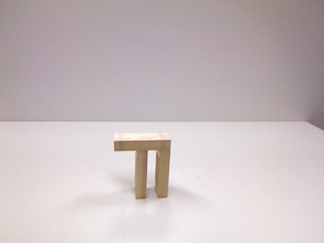
this idea and reattempted a fully data driven approach                         Visual Stability Prediction
to capturing the essence of physical events via machine
learning methods (Mottaghi et al., 2016; Wu et al., 2015;
Fragkiadaki et al., 2016; Bhattacharyya et al., 2018).
                                                                               Unstable        Stable        Stable   Unstable
   In the first part of this work, we draw inspiration from
the studies in developmental psychology (Baillargeon,
1994, 2008) where the infants acquire the knowledge of                          Manipulation
physical events gradually through the observation of var-
ious event instances. In this context, we revisit the classi-
cal setup of Tenenbaum and colleagues (Battaglia et al.,
2013) and explore to which extent machines can predict
physical stability events directly from appearance cues.
We approach this problem by synthetically generating a
large set of wood block towers under a range of condi-
tions, including varying number of blocks, varying block
sizes, planar vs. multi-layered configurations. We run
those configurations through a simulator (only at training
                                                                    Figure 1: Given a wood block structure, our vi-
time!) in order to generate labels whether a tower would
fall or not. We show for the first time that the afore-
                                                                    sual stability classifier predicts the stability for future
mentioned stability test can be learned and predicted in            placements, and the robot then stacks a block among
a purely data driven way—bypassing traditional model-               the predicted stable placements.
based simulation approaches. Further, we accompany our
experimental study with human judgments on the same
stimuli. Then we utilize this framework to guide the robot
to stably stack a single block onto the existing block-
structure based on the stability prediction. To circumvent          to guide the agent to build different shapes on request.
the domain shift between the synthesized images and the             We first validated this model on a toy example where the
real world scene images, we extract the foreground masks            agent has to navigate in a grid-world where both the lo-
for both synthesized and captured images. Given a real              cation of the start and end point are randomized for each
world block structure, the robot uses the model trained             episode and then the target stacking. On both experi-
on the synthesized data to predict the stability outcome            ments, we observe generalization across different goals.
across possible candidate placements, and performs stack-
ing on the feasible locations afterwards. We evaluate both             We tackle the block stacking task, by focusing the
the prediction and manipulation performance on the very             manipulation learning with respect to the correspond-
task.                                                               ing physics constraints underneath the task. The first
   In the second part of this work, we further tackle a more        part of the work emphasizes the visual stability predic-
challenging stacking task (target stacking). The goal for           tion formalism and its application to single block stacking
the task is to reproduce a shape shown in an image by con-          task that was initially presented in Li et al. (2017). The
secutively stacking multiple blocks while retaining phys-           second part of the work features an extension to goal-
ical stability and avoiding pre-mature collisions with the          parametrized deep reinforcement learning framework and
existing structure. We explore an alternative modeling to           its application to target stacking task. In addition, we
learn the block stacking through trial-and-error, bypass-           now include a discussion of the simulation environment
ing the need to explicitly model the corresponding physics          implemented for both tasks. While simulation engines
knowledge as in the former part of this work. For this pur-         and game engines, such as Panda3D (Goslin and Mine,
pose, we build a synthetic environment with physics sim-            2004), provide a generic platform to devise environment
ulation, where the agent can move and stack blocks and              to different needs, it is still very time-consuming and re-
observe the different outcomes of its actions. We apply             mains non-trivial to customize one for a specific tasks such
deep reinforcement learning to directly acquire the block           as the target stacking in this work. Hence, we briefly re-
stacking skill in an end-to-end fashion. By introducing             cap our design for the environments to provide readers
the goal-parameterized policies, we learn a single model            more insights for further practice.

                                                                2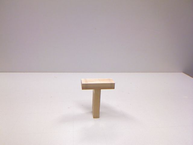
2     Related Work                                                 berman et al. (2012) from image data, and object segmen-
                                                                   tation in 3D point cloud data Zheng et al. (2013). An-
2.1     Physics Understanding                                      other research direction is to equip artificial agents with
                                                                   such an ability by letting them learn physical concepts
Humans possess the amazing ability to perceive and un-             from visual data. Mottaghi et al. (2016) aim at under-
derstand ubiquitous physical phenomena occurring in                standing dynamic events governed by laws of Newtonian
their daily life. This gives rise to the concept of intu-          physics and use proto-typical motion scenarios as exem-
itive physics, aiming to describe the knowledge which en-          plars. Fragkiadaki et al. (2016) analyze billiard table sce-
ables humans to understand physical environment and                narios and learn dynamics from observation with explicit
interact accordingly. In particular, the “intuitive” part          object notion. An alternative approach based on bound-
emphasizes knowledge which is considered commonsense               ary extrapolation Bhattacharyya et al. (2018) addresses
to ordinary people not reliant on specialized training in          similar settings without imposing any object notion. Wu
physics. Intuitive physics is ubiquitous in guiding hu-            et al. (2015) aims to understand physical properties of
mans’ actions in daily life, such as where to put a cup            objects based on explicit physical simulation. Mottaghi
stably and how to catch a ball. Along the years, research          et al. (2017) proposes to reason about containers and the
on intuitive physics has been conducted from many differ-          behavior of the liquids inside them from a single RGB
ent perspectives across psychology, cognitive science and          image.
artificial intelligence.                                              A most related work is done by Lerer et al. (2016),
   In developmental psychology, researchers seek to un-            where the authors propose using a visual model to predict
derstand how this ability develops. Baillargeon (2002)             stability and falling trajectories for simple 4 block scenes.
suggest that infants acquire the knowledge of physical             In the first part of this work, we investigate if and how
events at a very young age by observing those events,              the prediction performance of such image-based models
including support events and others. Interestingly, in a           changes when trained on block stacking scenes with larger
recent work Denil et al. (2017), the authors introduce a           variety and further examine how the human’s prediction
basic set of tasks that require the learning agent to es-          adapts to the variation in the generated scenes and com-
timate physical properties (mass and cohesion combina-             pare to the learned visual model. Each work requires
tions) of objects in an interactive simulated environment          significant amounts of simulated, physically-realistic data
and find that it can learn to perform the experiments              to train the large-capacity, deep models.
strategically to discover such hidden properties in analogy
to human’s development of physics knowledge. Another
interesting question that has been explored in psychology          2.2     Learning from Synthetic Data and
is how knowledge about physical events affects and guides                  Simulation
human’s actual interaction with objects Yildirim et al.
(2017). Yet it is not clear how a machine model trained            Learning from synthetic data has a long tradition in com-
for physics understanding can directly be applied to real-         puter vision and has recently gained increasing interest
world interactions with objects and accomplish manipu-             (Li and Fritz, 2012; Rematas et al., 2014; Peng et al.,
lation tasks.                                                      2015; Rematas et al., 2016) due to data hungry deep-
   In cognitive science, Battaglia et al. (2013) proposes an       learning approaches. In the first part of this work, we
intuitive physics simulation engine as an internal mecha-          use a game engine to render scene images and a built-in
nism for such type of ability and found close correlation          physics simulator to simulate the scenes’ stability behav-
between its behavior patterns and human subjects’ on               ior. The data generation procedure is based on the plat-
several psychological tasks.                                       form used in Battaglia et al. (2013), however as discussed
   More recently, there has been renewed interest in               before, their work hypothesized a simulation engine as an
physics understanding in computer vision and machine               internal mechanism for human to understand the physics
learning communities. For instance, understanding phys-            in the external world while we are interested in finding
ical events plays an important role in scene understanding         an image-based model to directly predict the physical be-
in computer vision. By including additional clues from             havior from visual channel.
physical constraints into the inference mechanism, mostly             In reinforcement learning domain, it is a common prac-
from the support event, it has further improved results in         tice to utilize simulation environment to train the re-
segmentation of surfaces Gupta et al. (2010), scenes Sil-          inforcement agent, such as the Atari Games (Bellemare

                                                               3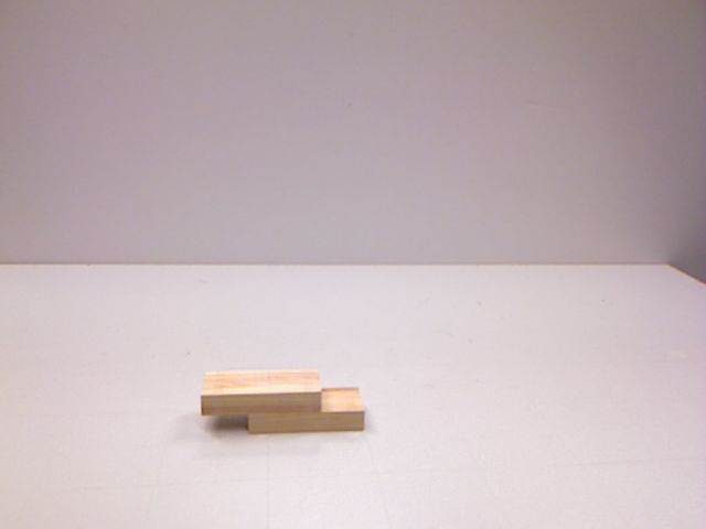
et al., 2013) and ViZDoom (Kempka et al., 2016). How-               model learned towards a specific goal to a different one.
ever, there is no off-the-shelf environment supporting              An early idea has been proposed by Kaelbling (1993) for
trial-and-error interaction for block stacking. Hence, in           a maze navigation problem in which the goal changes.
the second part of this work, we build on existing game en-         The author introduces an analogous formulation to the
gine and create our interactive environment with physics            Q-learning by using shortest path in replacement of the
simulation to allow the learning agent to learn stacking            value functions. Yet there are two major limitations for
skills through interactions.                                        the framework: 1) it is only formulated in tabular form
                                                                    which is not practical for application with complex states
                                                                    2) the introduced shortest path is very specific to the maze
2.3     Blocks-based Manipulation Tasks                             navigation setting and hence cannot be easily adapt to
To shed more light on the capabilities of our model, in the         handle task like target stacking. In contrast, we propose
first part of this work, we explore how the visual stabil-          a goal-parameterized model to integrate goal information
ity prediction model can be used in a robotic manipula-             into a general learning-based framework that facilitates
tion task, i.e., stably stacking a wood block given a block         generalization across different goals. The model has been
structure. In the past, we have seen researchers perform            shown to work on both a navigation task and target stack-
tasks with wood blocks, like playing Jenga from different           ing.
perspectives. Kröger et al. (2006) demonstrated multi-                A few other works also explored the idea of integrating
sensor integration by using a marker-based system with              goal information into learning. Schaul et al. (2015) pro-
multiple cameras and sensors: a random block is first cho-          pose the universal value function approximators (UVFAs)
sen in the tower, then the robot arm will try to pull the           to integrate goal information into learning. Oh et al.
very block, if the force sensor detects large counter force         (2017) proposes zero-shot task generation with explicit
or the CCD cameras detect large motion of tower, then               modeling of skills and subtasks where our approach is
it will stop pulling and try other block.                           end-to-end and thereby bypasses this kind of modeling.
   Wang et al. (2009) improved on Kröger et al. (2006)             Dosovitskiy and Koltun (2017) use the terms “goal” and
by further incorporating a physics engine to initialize the         “target”. However, their notion is different from ours.
candidates for pulling test. In comparison, we do not fit           Their framework is using auxiliary information (interme-
3D models or run physics simulation at test time for the            diate measurements as goal module) to improve learning
given scene but instead use the scene image as input to             to maximize gaming score in visually-richer task like viz-
directly predict the physics of the structure.                      Doom. There is no specific goal to enforce the agent to
   A different line of research is Kimura et al. (2010) where       reach certain state which is exactly what our approach
physical force is explicitly formulated with respect to the         facilitates. The metacontroller (Hamrick et al., 2017),
tower structure for planning. In our work, we do not                the imagination strategy (Pascanu et al., 2017) and the
do explicit formation of contact force as in Kimura et al.          I2A model (Weber et al., 2017) are all appealing generic
(2010), nor do we perform trials on-site for evaluating the         frameworks to boost overall performance over existing RL
robot’s operation. We only use physics engine to acquire            methods. While these approaches – similar to some of
synthesized data for training the visual-physics model. At          the Atari games – have a goal encoded in the observa-
test time, the planning system for our robot mainly ex-             tion/state, this goal remains implicit. This is applicable
ploits the knowledge encoded in the visual-physics model            in many robotic scenarios, where goals are specified ex-
to evaluate the feasibility of individual candidates and            ternally. Therefore, we explore an approach for target
performs operations accordingly.                                    stacking that has an explicit notion and model of goals.
                                                                    Our work is the first to bring this concept to bear towards
                                                                    manipulation and planing under physical constraints –
2.4     Reinforcement Learning                                      breaking with more conventional simulation and planning
In the second part of this work, reinforcement learning             approaches (e.g. Yildirim et al. (2017)).
is used to learn an end-to-end model directly from the
experience collected during interaction with a physically-
realistic environment. The majority of work in reinforce-           3     Simulation Environment
ment learning focuses on solving task with a single goal.
However, there are also tasks where the goal may change             Modern machine learning techniques build on data. With
for every trial. It is not obvious how to directly apply the        the rise of deep learning models, the need of data be-

                                                                4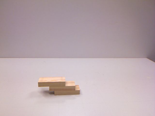
comes even more prominent. One of the key elements for                                              Render
the recent success of deep learning model in domains like
generic image and speech recognition is the abundance
of data in related fields. However, when it comes to a                  LensNode                 LightNode           ...      ModelNode
specific domain, it often runs short of data and in reality,
collecting data is still an expensive process. One remedy
for this issue is to exploit the domain knowledge to syn-              Type         ...   Type      Color      ...          State      ...

thesize data and utilize the generated data for learning.
This is also the case for our study as there is no obvi-            Figure 2: An example of scene graph in Panda3D.
ous source of clean and sufficient data to learn physics
from. Hence, we make use of the Panda3D 1 to create
both simulation environments in our work.                                                            Render
   Panda3D is an open source game engine for Python
and C++ programs. It was originally developed by the                                                   ...
Disney’s VR studio to be “flexible enough to support ev-
                                                                                                      Task i
erything from realtime graphics applications to the de-
                                                                                                       ...
velopment of high-end virtual reality theme park attrac-
                                                                              Event Handler
tions or video games” (Goslin and Mine, 2004) and it has
evolved significantly along the years.
   As a game engine, the Panda3D provides additional ca-
pabilities besides 3D rendering including the physics sys-
tem with integration of different physics engines. Asides                     ...         Frame t              Frame t+1         ...

from its own built-in basic physics engine, it also supports                                                               Sequence
more advanced ones including the Open Dynamics Engine
(ODE) 2 (Smith, 2005) and the Bullet 3 (Coumans, 2010)                    Figure 3: The render process in Panda3D.
for physics simulation back-end. We used the Bullet in
both of our simulation environments.
   The workflow of Panda3D builds on the concept of
                                                                   objects in the scene caused by physics.
scene graph. The Scene graph is a general data struc-
ture to represent and organize a graphical scene. In
Panda3D, the scene graph is maintained as a tree of
objects to be rendered. The tree consists of objects of            4      Part I: From Visual Stabil-
class PandaNode. As shown in Figure 2, the root node is
called the render and the rest define different perspec-                  ity Prediction to Single Block
tives of the scene with various attributes. For example,                  Stacking
the LensNode controls the camera such as the perspective,
the LightNode manages the lighting in the scene such as
the color and type of the lighting and the ModelNode en-           4.1        Stability Prediction from Still Im-
codes the 3D object in the frame.                                             ages
   Another important concept is the task. Tasks are func-
tions called by Panda3D at every frame or for every speci-         Inspiration from Human Studies Research in
fied amount of time. Together with event handler which             Hamrick et al. (2011); Battaglia et al. (2013) suggests the
is called upon special conditions (events) occur, update           combinations of the most salient features in the scenes are
can be made to the scene in Panda3D between rendering              insufficient to capture people’s judgments, however, con-
steps as shown in Figure 3. For instance, the task can             temporary study reveals human’s perception of visual in-
be the simulation subroutine that updates the states of            formation, in particular some geometric feature, like criti-
                                                                   cal angle Cholewiak et al. (2013, 2015) plays an important
  1 https://www.panda3d.org/                                       role in the process. Regardless of the actual inner mecha-
  2 http://www.ode.org/                                            nism for humans to parse the visual input, it is clear there
  3 http://bulletphysics.org/wordpress/                            is a mapping f involving visual input I to the stability

                                                               5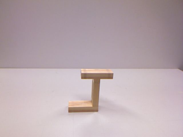
Scene     Scene Image              Stability
                     Physics Engine                     Training

                         Train              Stability                                                                            Stable
       Train Set
                        Images              Labels                                                       Simulation

    Scene          Rendering Engine     Visual-Stability Classifier        Generation

                                           Stability      Test
        Test Set      Test Images                                                                                               Unstable
                                          Prediction
                                                                                                         Simulation

                                                                                           ...
Figure 4: An overview of our approach for learning
visual stability. Note that physics engine is only used
during training time to get the ground truth to train Figure 5: Overview of the data generator for visual
the deep neural network while at test time, only ren- stability prediction. The scene images and their cor-
dered scene images are given to the learned model to responding stability labels are collected.
predict the physical stability of the scenes.
                                                                          4.2           Data Generator for Visual Stabil-
                                                                                        ity Prediction
prediction P .
                                                                          Based on the scene simulation framework used in (Ham-
                         f : I, ∗ → P                                     rick et al., 2011; Battaglia et al., 2013), we build a data
                                                                          generator to synthesize data for visual stability tests. Fig-
                                                                          ure 5 gives an overview of the data generator. The first
Here, ∗ denotes other possible information, i.e., the map-                key component is the tower generation. It automat-
ping can be inclusive, as in Hamrick et al. (2011) using it               ically generate a large number of different blocks struc-
along with other aspects, like physical constraint to make                tures (tower) under the scene parameters, including the
judgment or the mapping is exclusive, as in Cholewiak                     number of blocks, stacking depth and block size (We will
et al. (2013) using visual cues alone to decide.                          elaborate on this later). These towers are recorded as
                                                                          scene files which only track all the locations of blocks in
                                                                          the scene.
Image Classifier for Stability Prediction In our                             The next component is the stability simulation. It
work, we are interested in the mapping f exclusive to                     loads the stored scene files and simulates their stability
visual input and directly predicts the physical stability                 with physics engine. The images for the towers before
(visual stability test). To this end, we use deep convo-                  running the physics engine are captured as the scene im-
lutional neural networks as it has shown great success                    ages, the stability labels from the simulation are auto-
on image classification tasks (Krizhevsky et al., 2012).                  matically determined and recorded for the corresponding
Such networks have been shown to be able to adapt to a                    towers. Both the scene images and the obtained stabil-
wide range of classification and prediction task (Razavian                ity labels are later put into the deep convolutional neural
et al., 2014) through re-training or adaptation by fine-                  network to learn the visual stability classifier.
tuning. Therefore, these approaches seem to be adequate
methods to study visual prediction on this challenging
                                                                          4.2.1         Tower Generation
task with the motivation that by changing conventional
image classes labels to stability labels the network can                  An example of the scene setup is shown Figure 6. The
learn “physical stability salient” features. By setting up                tower is placed on a plane, and a camera is positioned at
a data generation process that allows us to control var-                  the front-facing location of which the elevation is adjusted
ious degrees of freedom induced by the problem as well                    for the towers of different heights. For different scenes, the
as generation of large quantities of data in a repeatable                 towers are generated differently, and the scene images are
setting, we can then validate our approach. An overview                   captured through the camera. To make the scene images
of our approach is shown in Figure 4.                                     more realistic, wood texture is added to all the blocks.

                                                                      6
the blocks in stable towers can generate small displace-
                                  Camera                                ment during the simulation process, simply using zero
                                                                        displacement to determine the stability can lead to lots
                                                                        of erroneous cases where the stable towers are labeled as
                                                                        unstable. In practice, we picked the threshold based on
                 Tower                                                  the evaluation of a small set of towers.

                                                                        4.3     Synthetic Data
                                           Plane
                                                                        The number of blocks, blocks’ size and stacking depth are
Figure 6: Example set-up of the scene for the data                      varied in the generated scenes, to which we will refer as
generator.                                                              scene parameters.

                                                                        Numbers of Blocks We expect that varying the size
                                                                        of the towers will influence the difficulty and challenge
                                                                        the competence of “eye-balling” the stability of a tower
                                                                        in humans and machine. While evidently the appear-
                                                                        ance becomes more complex with the increasing number
 (a) 4 Blocks (b) 6 Blocks (c) 10 Blocks (d) 14 Blocks                  of blocks, the number of contact surfaces and interactions
                                                                        equally make the problem richer. Therefore, we include
Figure 7: Example of generated scene images with                        scenes with four different number of blocks, i.e., 4 blocks,
different total number of blocks.                                       6 blocks, 10 blocks and 14 blocks as {4B, 6B, 10B, 14B}.

   The basic tower generation system is based on the
                                                                        Stacking Depth As we focus our investigations on
                                                                        judging stability from a monocular input, we vary the
framework by Battaglia et al. (2013). Given a speci-
                                                                        depth of the tower from a one layer setting which we call
fied number of total blocks in the tower, the blocks are
                                                                        2D to a multi-layer setting which we call 3D. The first
sequentially added into the scene under the geometrical
                                                                        one only allows a single block along the image plane at
constraints, such as no collision between blocks. Some
                                                                        all height levels while the other does not enforce such
examples of obtained scene images are shown in Figure 7.
                                                                        constraint and can expand in the image plane. Visu-
                                                                        ally, the former results in a single-layer stacking similar to
4.2.2    Stability Simulation                                           Tetris while the latter ends in a multiple-layer structure
During the stability simulation, we set the simulation                  as shown in Table 1. The latter most likely requires the
time universally to 2 seconds at 1000Hz for all the scenes.             observer to pick up on more subtle visual cues, as many
Surface friction and gravity are enabled in the simula-                 of its layers are heavily occluded.
tion. The system records the configuration of a scene of
N blocks at time t as (p1 , p2 , ..., pN )t , where pi is the lo-       Block Size We include two groups of block size set-
cation for block i. The stability is then automatically                 tings. In the first one, the towers are constructed of blocks
decided as a Boolean variable:                                          that have all the same size of 1 × 1 × 3 as in the Battaglia
                  N
                  _                                                     et al. (2013). The second one introduces varying block
             S=       (∆((pi )t=T − (pi )t=0 ) > τ )                    sizes where two of the three dimensions are randomly
                  i=1
                                                                        scaled with respect to a truncated Normal distribution
where T is the end time of simulation, δ measures the dis-              N (1, σ 2 ) around [1 − δ, 1 + δ], σ and δ are small values.
placement for the blocks between the starting
                                           W point and                  These two settings are referred to as {Uni, NonU ni}. The
end time, τ is the displacement threshold,    denotes the               setting with non-uniform blocks introduces small visual
logical Or operator, that is to say it counts as unstable               cues where stability hinges on small gaps between differ-
S = True if any block in the scene moved in simula-                     ently sized blocks that are challenging even for human
tion, otherwise as stable S = False. This is necessary as               observers.

                                                                    7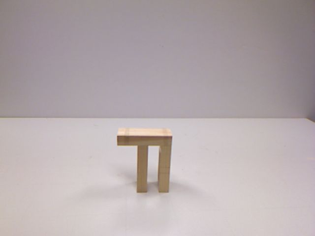
Scenes Combining these three scene parameters, we feasibility of our task.
define 16 different scene groups. For example, group 10B-
2D-Uni is for scenes stacked with 10 Blocks of same size,            Number of Blocks (4B, 6B, 10B, 14B) In this
stacked within a single layer. For each group, 1000 candi-           group of experiment, we fix the stacking depth and keep
date scenes are generated where each scene is constructed            the all blocks in the same size but vary the number of
with non-overlapping geometrical constraint in a bottom-             blocks in the scene to observe how it affects the predic-
up manner. There are 16K scenes in total. For prediction             tion rates from the image trained model, which approx-
experiments, half of the images in each group are for train-         imates the relative recognition difficulty from this scene
ing and the other half for test, the split is fixed across the       parameter alone. The results are shown in Table 2. A
experiments.                                                         consistent drop of performance can be observed with in-
                                                                     creasing number of blocks in the scene under various block
Rendering While we keep the rendering basic, we like                 sizes and stacking depth conditions. More blocks in the
to point out that we deliberately decided against colored            scene generally leads to higher scene structure and hence
bricks as in Battaglia et al. (2013) in order to challenge           higher difficulty in perception.
perception and make identifying brick outlines and con-
figurations more challenging. The lighting is fixed across
                                                                     Block Size (Uni. vs. NonUni.) In this group of
scenes and the camera is automatically adjusted so that
                                                                     experiment, we aim to explore how same size and var-
the whole tower is centered in the captured image. Images
                                                                     ied blocks sizes affect the prediction rates from the image
are rendered at resolution of 800 × 800 in color.
                                                                     trained model. We compare the results at different num-
                                                                     ber of blocks to the previous group, in the most obvious
4.4     Prediction Performance                                       case, scenes happened to have similar stacking patterns
                                                                     and same number of blocks can result in changes visual
In this part of the experiments, the images are captured
                                                                     appearance. To further eliminate the influence from the
before the physics engine is enabled, and the stability la-
                                                                     stacking depth, we fix all the scenes in this group to be
bels are recorded from the simulation engine as described
                                                                     2D stacking only. As can be seen from Table 2, the per-
before. At the training time, the model has access to
                                                                     formance decreases when moving from 2D stacking to 3D.
the images and the stability labels. At test time, the
                                                                     The additional variety introduced by the block size indeed
learned model predicts the stability results against the
                                                                     makes the task more challenging.
results generated by the simulator.
   In a pilot study, we tested on a subset of the gen-
erated data with LeNet (LeCun et al., 1995), a rel-                  Stacking Depth (2D vs. 3D) In this group of ex-
atively small network designed for digit recognition,                periment, we investigate how stacking depth affects the
AlexNet (Krizhevsky et al., 2012), a large network and               prediction rates. With increasing stacking depth, it natu-
VGG Net (Simonyan and Zisserman, 2014), an even larger               rally introduces ambiguity in the perception of the scene
network than AlexNet. We trained from scratch for the                structure, namely some parts of the scene can be occluded
LeNet and fine-tuned for the large network pre-trained               or partially occluded by other parts. Similar to the ex-
on ImageNet Deng et al. (2009). VGG Net consistently                 periments in previous groups, we want to minimize the
outperforms the other two, hence we use it across our ex-            influences from other scene parameters, we fix the block
periment. We use the Caffe framework (Jia et al., 2014)              size to be the same and only observe the performance
in all our experiments.                                              across different number of blocks. The results in Table 2
   We divide the experiment design into 3 sets: the intra-           show a little inconsistent behaviors between relative sim-
group, cross-group and generalization. The first set in-             ple scenes (4 blocks and 6 blocks) and difficult scenes (10
vestigates influence on the model’s performance from an              blocks and 14 blocks). For simple scenes, prediction ac-
individual scene parameter, the other two sets explore               curacy increases when moving from 2D stacking to 3D
generalization properties under different settings.                  while it is the other way around for the complex scene.
                                                                     Naturally relaxing the constraint in stacking depth can
                                                                     introduce additional challenge for perception of depth in-
4.4.1    Intra-Group Experiment
                                                                     formation, yet given a fixed number of blocks in the scene,
In this set of experiments, we train and test on the scenes          the condition change is also more likely to make the scene
with the same scene parameters in order to assess the                structure lower which reduces the difficulty in perception.

                                                                 8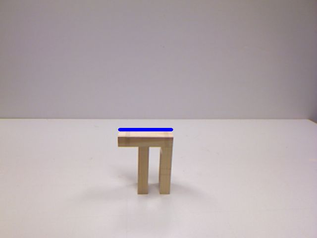
Block Numbers                                              Stacking Depth                                Block Size

 (a)   4 Blocks   (b)   6 Blocks    (c)   10 Blocks     (d) 14 Blocks        (e)   2D-stack   (f)   3D-stack             (g)   size-fix     (h)   size-vary

Table 1: Overview of the scene parameters in our rendered scenes. There are 3 groups of scene parameters
across number of blocks, stacking depth and block size.

           # Blks          Uni.                 NonUni.                                                 Simple2Complex

                        2D         3D                 2D
                                                                                                        Complex2Simple

             4B         93.0   99.2                   93.2
             6B         88.8   91.6                   88.0
                                                                             Setting            Simple → Complex Complex → Simple
            10B         76.4   68.4                   69.8
            14B         71.2   57.0                   74.8                   Accuracy (%)               69.9                              86.9

Table 2: Intra-group experiment by varying scene pa- Table 3: The upper figure shows the experiment set-
rameters.                                            tings for Cross-group classification where we train on
                                                     simpler scenes and test on more complex scenes. The
                                                     lower table shows the results.
A combination of these two factors decides the final dif-
ficulty of the task, for simple scenes, the height factor
has stronger influence and hence exhibits better predic-                     2. Train on complex scenes and predict on simple
tion accuracy for 3D over 2D stacking while for complex                         scenes: Train on 10 and 14 blocks and test on 4
scenes, the stacking depth dominates the influence as the                       and 6 blocks
significant higher number of blocks can retain a reason-                       As shown in Table 3, when trained on simple scenes
able height of the structure, hence receives decreased per-                 and predicting on complex scenes, it gets 69.9%, which
formance when moving from 2D stacking to 3D.                                is significantly better than random guess at 50%. This
                                                                            is understandable as the learned visual feature can trans-
4.4.2     Cross-Group Experiment                                            fer across different scene. Further we observe significant
                                                                            performance boost when trained on complex scenes and
In this set of experiment, we want to see how the learned                   tested on simple scene. This can be explained by the
model transfers across scenes with different complexity, so                 richer feature learned from the complex scenes with bet-
we further divide the scene groups into two large groups                    ter generalization.
by the number of blocks, where a simple scene group for
all the scenes with 4 and 6 blocks and a complex scene for
the rest of scenes with 10 and 14 blocks. We investigate in                 4.4.3     Generalization Experiment
two-direction classification, shown in the figure in Table 3:
                                                                            In this set of experiment, we want to explore if we can
  1. Train on simple scenes and predict on complex                          train a general model to predict stability for scenes with
     scenes: Train on 4 and 6 blocks and test on 10 and                     any scene parameters, which is very similar to human’s
     14 blocks                                                              prediction in the task. We use training images from all

                                                                        9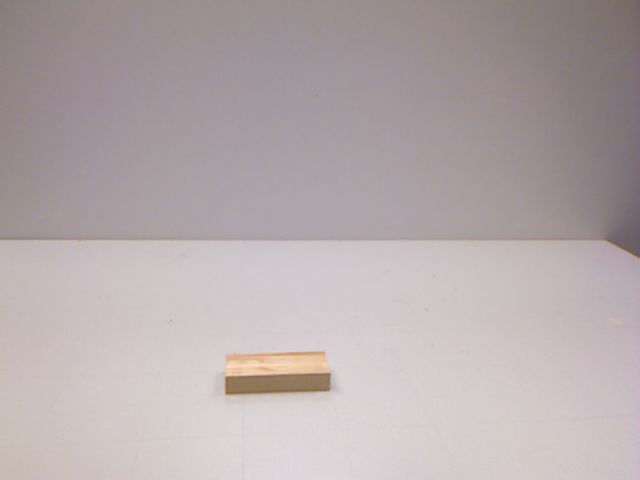
- although the appearance difference can be quite small.
         # Blks            Uni.                NonUni.
                                                                  To better understand our results, we further discuss the
                                                                  following two questions:
                        2D      3D             2D        3D
                                                                     How does the model performs compared to hu-
                                                                  man? To answer this, we conduct a human subject test.
             4B         93.2    99.0          95.4      99.8
                                                                  We recruit human subjects to predict stability for give
             6B         89.0    94.8          87.8      93.0      scene images. Due to large number of test data, we sam-
                                                                  ple images from different scene groups for human subject
             10B        83.4    76.0          77.2      74.8
                                                                  test. 8 subjects are recruited for the test. Each subject
             14B        82.4    67.2          78.4      66.2      is presented with a set of captured images from the test
                                                                  split. Each set includes 96 images where images cover all
  Table 4: Results for generalization experiments.                16 scene groups with 6 scene instances per group. For
                                                                  each scene image, subject is required to rate the stability
                                                                  on a scale from 1 − 5 without any constraint for response
    # Blks              Uni.                NonUni.               time:
                                                                      1. Definitely unstable: definitely at least one block will
                   2D          3D         2D           3D                move/fall
        4B     79.1/91.7   93.8/100.0   72.9/93.8   92.7/100.0
                                                                      2. Probably unstable: probably at least one block will
                                                                         move/fall
        6B     78.1/91.7   83.3/93.8    71.9/87.5   89.6/93.8
                                                                      3. Cannot tell: the subject is not sure about the sta-
     10B       67.7/87.5   72.9/72.9    66.7/72.9    71.9/68.8
                                                                         bility
     14B       71.9/79.2   68.8/66.7    71.9/81.3   59.3/60.4         4. Probably stable: probably no block will move/fall
                                                                      5. Definitely stable: definitely no block will move/fall
Table 5: Results from human subject test a and cor-
                                                       The predictions are binarized, namely 1) and 2) are
responded accuracies from image-based model b in treated as unstable prediction, 4) and 5) as stable predic-
format a/b for the sampled data.                    tion, “Cannot tell” will be counted as 0.5 correct predic-
                                                                  tion.
                                                                     The results are shown in Table 5. For simple scenes
different scene groups and test on any groups. The Re-            with few blocks, human can reach close to perfect perfor-
sult is shown in Table 4. While the performance exhibits          mance while for complex scenes, the performance drops
similar trend to the one in the intra-group with respect to       significantly to around 60%. Compared to human predic-
the complexity of the scenes, namely increasing recogni-          tion in the same test data, the image-based model out-
tion rate for simpler settings and decreasing rate for more       performs human in most scene groups. While showing
complex settings, there is a consistent improvement over          similar trends in performance with respect to different
the intra-group experiment for individual groups. To-             scene parameters, the image-based model is less affected
gether with the result in the cross-group experiment, it          by a more difficult scene parameter setting, for example,
suggests a strong generalization capability of the image          given the same block size and stacking depth condition,
trained model.                                                    the prediction accuracy decreases more slowly than the
                                                                  counter part in human prediction. We interpret this as
4.4.4    Discussion                                               image-based model possesses better generalization capa-
                                                                  bility than human in the very task.
Overall, we can conclude that direct stability prediction             Does the model learn something explicitly in-
is possible and in fact fairly accurate at recognition rates      terpretable? Here we apply the technique from Zhou
over 80% for moderate difficulty levels. As expected, the         et al. (2016) to visualize the learned discriminative im-
3D setting adds difficulties to the prediction from appear-       age regions from CNN for individual category. The ap-
ance due to significant occlusion for towers of more than         proach is illustrated in Figure 8a. With Global Aver-
10 blocks. Surprisingly, little effect was observed for small     age Pooling (GAP), the resulted spatial average of the
tower sizes switching from uniform to non-uniform blocks          feature maps from previous convolutional layers forms

                                                                 10
C1 Unstable
GAP Layer
F1
…
CONV
C2
CONV
Stable
CONV
CONV
CONV
W
Fk
…
Feature Map
Class Activation Mapping * W’ =
(b) Examples of CAM showing the dis-
criminative regions for unstable predic-
(a) By introducing the GAP layer directly connected to the final out- tion in comparison to the flow magni-
put, the learned weights can be backprojected to the feature map for tude indicating where the collapse mo-
each category to construct the CAM. The CAM can be used to visu- tion begins. For each example, from left
alize the discriminative image regions for individual category. to right are original image, CAM and
flow magnitude map.
Figure 8: We use CAM to visualize the results for model interpretation.
fully-connected layer to directly decides the final output. adjustments were made to the free-style stacking:
By back-projecting the weights from the fully-connected
• The given block structure is restricted to be single
layer from each category, we can hence obtain Class Acti-
layer as the 2D case in the previous section. For the
vation Map (CAM) to visualize the discriminative image
final test, we report results on the 6 scenes as shown
regions. In our case, we investigate discriminative regions
in Table 6.
for unstable predictions to see if the model can spot the
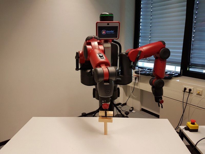
weakness in the structure. We use deep flowWeinzaepfel • The block to be put on top of the given structure is
et al. (2013) to compute the optical flow magnitude be- limited two canonical configurations {vertical, hori-
tween the frame before the physics engine is enabled and zontal} as shown in Figure 10b. and assumed to be
the one afterwards to serve as a coarse ground truth for held in hand of robot before the placement.
the structural weakness where we assume the collapse mo- • The block is constrained to be placed on the top-
tion starts from such weakness in the structure. Though most horizontal surface (stacking surface) in the
not universal among the unstable cases, we do find signif- given structure.
icant positive cases showing high correlation between the
• The depth of the structure (perpendicular distance
activation regions in CAM for unstable output and the re-
to the robot) is calibrated so that we only need to
gions where the collapse motion begins. Some examples
decide the horizontal and vertical displacements with
are shown in Figure 8b.
respect to the stacking surface.
In the previous section, we have shown that an
appereance-based model can predict physical stability rel-
atively well on the synthetic data. Now we want to fur-
4.5 Prediction on Real World Data
ther explore if and how the synthetic data trained model Considering there are significant difference between the
can be utilized for a real world application, especially synthesized data and real world captured data, including
for robotic manipulation. Hence, we decide to set up a factors (not limited to) as texture, illumination condition,
testbed where a Baxter robot’s task is to stack one wood size of blocks and accuracy of the render, we performed
block on a given block structure without breaking the a pilot study to directly apply the model trained on the
structure’s stability as shown in Figure 1. The overview RGB images to predict stability on the real data, but
of our system is illustrated in Figure 9. In our experiment, only got results on par with random guessing. Hence we
we use Kapla blocks as basic unit, and tape 6 blocks into decided to train the visual-stability model on the binary-
a bigger one as shown in Figure 10a. To simplify the task, valued foreground mask on the synthesized data and deal
11Current Scene Candidates’
Scene Image Configurations
Candidates’ Scene Image Stacking Surface
Visual-Stability Classifier
Images
Foreground Mask
Feasible
Actions
Configurations
Background Image Candidate Image
Figure 9: An overview of our manipulation system.
Vertical
Our visual-stability classifier is integrated to recog-
nize feasible candidate placement to guide manipula-
tion.
Horizontal
Vert
ic al
tal
Horizon
Figure 11: The procedure to generate candidates
placement images for a give scene in our experiment.
(a) Kapla block (left), block in (b) Allowed config-
test (right). urations in test. 4.6 Manipulation Test
Figure 10: Blocks used in our experiment. At test time, when the model predicts a give candidate
placement as stable, the robot will execute routine to
place the block with 3 attempts. We count the execution
as a success if any of the attempt works. The manipula-
with the masks at test time also for the real scenes. In tion success rate is defined as:
this way, we significantly reduce the effect from the afore-
mentioned factors. Observing comparable results when #{successful placements}
using the RGB images, we continue to the approach on #{all stable placements}
real world data. where #{successful placements} is the number of
At test time, a background image is first captured for successful placements made by the robot, and
the empty scene. Then for each test scene (shown in Ta- #{all stable placements} is the number of all ground
ble 6), an image is captured and converted to foreground truth stable placements.
mask via background subtraction. The top-most hori- As shown in Table 6, the manipulation performance is
zontal boundary is detected as the stacking surface and good across most of the scenes for both horizontal and
then used to generate candidate placements: the surface vertical placements except for the 6-th scene where the
is divided evenly into 9 horizontal candidates and 5 ver- classifier predicts all candidates as unstable hence no at-
tical candidates, resulting in 84 candidates. The process tempts have been made by the robot.
is shown in Figure 11. Afterwards, these candidates are
put to the visual-stability model for stability prediction.
Each generated candidate’s actual stability is manually
4.7 Discussion
tested and recorded as ground truth. The final recogni- Simply putting the block along the center of mass (COM)
tion result is shown in Table 6. The model trained with of the given structure may often be a feasible option, yet,
synthetic data is able to predict with overall accuracy of there are two limitations to this approach: first, it is non-
78.6% across different candidates in real world. trivial to compute the COM of a given structure; second,
12Id. 1 2 3 4 5 6
Scene
Pred.(%) 66.7 100.0 66.7 60.0 88.9 100.0 77.8 80.0 100.0 40.0 66.7 60.0
Mani.(%) 80.0(4/5) 100.0(5/5) 66.7(2/3) 100.0(3/3) 66.7(2/3) 100.0(1/1) 66.7(2/2) 66.7(2/3) 100.0(3/3) 25.0(1/4) 0.0(0/3) 0.0(0/1)
Placement H V H V H V H V H V H V
Table 6: Results for real world test. “Pred.” is the prediction accuracy. “Mani.” is the manipulation
success rate with counts for successful placements/all possible stable placements for each scene. “H/V” refer
to horizontal/vertical placement.
it only gives one possible stable solution (assuming it ac-
tually stay stable). In comparison, our method does not
rely the COM of the structure and provide a search over
multiple possible solutions.
So far, we have successfully applied our visual stability Target Shape Placement of Block 1 Placement of Block 2
prediction model to guide the stable placement of a single
block onto the existing structure. However, this approach
Figure 12: Target stacking: Given a target shape
has its own limitations. Firstly, it only deals with one image, the agent is required to move and stack blocks
manipulation step and does not take into account the to reproduce it.
interaction process which is also under physics constraint.
For instance, the block can collide with existing structure
before its placement. Secondly, it is also not obvious how ing. In this task, an image of a target structure made of
to extend the approach to plan a consecutive stacking of stacked blocks is provided. Given the same number of
multiple blocks. In part II, we will explore an alternative blocks as in the target structure, the goal is to repro-
approach to overcome these limitations. duce the structure shown in the image. The manipula-
tion primitives in this task include moving and placing
blocks. This is inspired by the scenario where young chil-
5 Part II: Beyond Single Block dren learn to stack blocks to different shapes given an
example structure. We want to explore how an artificial
Stacking — Target Stacking agent can acquire such a skill through trial and error.
In this part, we look at a manipulation task beyond the
single block placement as discussed in part I. We now
seek solutions to plan the placement of multiple blocks 5.1 Task Description
and consider more complex interactions in physical en-
vironment. In particular, just like children stack blocks For each task instance, a target structure is generated
towards a certain blueprint, we further introduce the ”tar- and its image is provided to the agent along with the
get” into the stacking task so that the sequence of ma- number of blocks. Each of these blocks has a fixed ori-
nipulations are planned to a achieve the target — similar entation. The sequence of block orientations is such that
to planning. Yet we want to stay fully in an end-to-end reproducing the target is feasible. The agent attempts to
learning approach – concerning the perception, physics as construct the target structure by placing the blocks in the
well as the plan, where intuitive physics as well as plan given sequence. The spawning location for each block is
execution is learned jointly. randomized along the top boundary of the environment.
The extended block stacking task is called target stack- A illustrative sample for the task is shown in Figure 12.
135.2 Task Distinction The environment now implements a more dynamic sys-
tem where different moves from the agent can lead to dif-
The following characteristics distinguish this task from ferent consequences: when a block (not the last one for
other tasks commonly used in the literature. the episode) is placed stably in the scene, a new block
should be spawned into the environment whereas if the
Goal-Specific A widely-used benchmark for deep re- block collapses the existing structure, the current episode
inforcement learning algorithm are the Atari games is terminated so that a new one can be started. The key
(Bellemare et al., 2013) that were made popular by Mnih to react correctly under these different conditions is to
et al. (2013). While this game collection has a large vari- detect them effectively.
ety, the games are defined by a single goal or no specific While we keep the essential parts of the task, at its
goal is enforced at a particular point in time. For example current stage the simulated environment remains an ab-
in Breakout, the player tries to bounce off as many bricks straction of a real-world robotics scenario. This gener-
as possible. In Enduro, the player tries to pass as many ally requires an integration of multiple modules for a full-
cars as possible while simultaneously avoiding cars. fledged working system, such as Toussaint et al. (2010),
In the target stacking task, each task instance differs in which is out of scope of this paper.
the specific goal (the target structure), and all the moves An overview of the stacking environment is shown in
are planned towards this goal. Given the same state, Figure 13. The environment is again implemented in
moves that were optimal in one task instance are unlikely Panda3D as the data generator described in the previous
to be optimal in another task instance with a different part. The block size follows a ratio of l : w : h = 5 : 2 : 1,
target structure. This is in contrast to games where one where l,w,h denote length, width and height respectively.
type of move will most likely work in similar scenes. This For each episode, a target structure is randomly picked
argument also applies to AI research platforms with richer from a pool of structures and then the blocks are spawned
visuals like VizDoom (Kempka et al., 2016). according to the target. The agent moves the spawned
block in the scene until the placement is done.
Longer sequences Target stacking requires looking During this process, if the agent’s move causes the
ahead over a longer time horizon to simultaneously en- block to (1) move out over the boundary of the scene or
sure stability and similarity to the target structure. This (2) collide with existing structure (3) collapse the struc-
is different from learning to poke (Agrawal et al., 2016) ture with the placement, the episode is terminated and a
where the objective is to select a motion primitive that is new episode can start.
the optimal next action. It is also different from the work A new block is spawned upon the previous one is placed
by Li et al. (2017) that reasons about the placement of successfully till reaching the total number of blocks in the
one block. target. When all the blocks are placed in the scene, the
environment determines if the agent achieves the assigned
target structure.
Rich Physics Bounded Besides stacking to the as- We ignore the impact during block placement and fo-
signed target shape the agent needs to learn to move the cus on the resulting stability of the entire structure. Once
block without colliding with the environment and exist- the block makes contact with the existing structure, it
ing structure and to choose the block’s placement wisely is treated as releasing the block for a placement. The
not to collapse the current structure. The agent has no physics simulation runs at 60Hz. However considering
prior knowledge of this. It needs to learn everything from the cost of simulation we only use it when there is con-
scratch by observing the consequence (collision, collapse) tact between the moving block and the boundary or the
of its actions. existing structure. Otherwise, the current block is moving
without actual physics simulation.
5.3 Target Stacking Environment
5.3.1 State Representation
Compared to the environment for visual stability predic-
tion as a data generator, we now need more a more capa- To further reduce the appearance difference caused by
ble task environment supports the learning process with varying perspective, the state in the stacking environ-
which the agent can interact. This requires us to signifi- ment is rendered using orthographic projection. It is im-
cantly extend the implementation. plemented by the OrthographicLens in Panda3D where
14New Episode plementation, the blocks have to be set with coordinates
Spawn
in continuous values, so a separate binary matrix is used
Target
Agent
to maintain the discrete representation of the state where
← → ↑ ↓
1 denotes the block presence in the cell and 0 otherwise.
Random
h
w
ℓ
Agent
← → ↑ ↓
New Episode
Figure 15: State representation in the stacking envi-
ronment
✓ ×
The environment can query both the rendered image
Figure 13: Overview of design for the target stacking
from the camera and the grid map for the state’s rep-
environment. resentation, though in our current experiments, we use
mostly the grid map for a simplified representation. An-
other benefit from the grid map representation is that it
can be used as a occupancy map which is crucial for our
implemented collision detection mechanism discussed in
the next subsection.
5.3.2 Collision and Stability Detection
As the block is maneuvered in the environment, it will
eventually make contact with the scene. The occurrence
(a) (b)
of contact marks an important transition of the state for
the environment. As shown in Figure 16:
Figure 14: Different perspective lens used in this the-
sis.(a): Perspective projection. (b): Orthographic
projection. Y
Simulation Stability Detection
Vertical
Move Contact Detection
parallel lines stay parallel and don’t converge as shown in
Figure 14b. This is in contrast with regular perspective Y
Move Collision Detection
camera used in the visual stability prediction environment Horizontal
as shown in Figure 14a.
Additionally, as we consider the action in discrete
space, namely {left,right,down} for the task, the state
Figure 16: Process of collision and stability detection
representation can also be formalized correspondingly as
shown in Figure 15. The individual block size follows a ra-
tio of l : w : h = 5 : 2 : 1, where l,w,h denote length, width If the contact is made by a block from above (verti-
and height respectively. With the aforementioned ortho- cal), it suggests a placement 4 , then physics simulation is
graphic camera, only length and height are preserved on called to obtain the stability. The stability detection is
the projected image with a ratio of l : h = 5 : 1. Each implemented the same way as the one used in the data
action moves the block by a displacement of the block’s 4 In our environment, we simplify the release movement
height along its direction. Hence the state can be repre- from the real world block placement, i.e. the block is deemed
sented in a grid map of unit square cells with length of to be released once it makes vertical contact with the scene,
the block’s height (u in the image space). In actual im- either the ground or the structure in the scene.
15generator for visual stability prediction. Here the simu-
lation only activates upon vertical contact is detected to
save runtime. If the block remains stable in the scene and
is not the last block for the episode, a new block is then
spawned at the top of the scene with random horizontal
location. If the block is the final one and remains stable +
or it collapses the structure in the scene, then the current
Scene Current Grid Map Foreground Map
episode is terminated and a new episode can be started.
If the contact is made by a horizontal movement, it will
not directly affect the current episode. If an additional +
move causes the collision, then the episode will be ter- Background Map
Contact Detected
minated, otherwise the block can be moved further until
Non-empty
either vertical contact happens, it goes into the simula-
tion and stability-detection branch or collision and termi-
Incoming Grid Map Incoming Foreground Map
nated.
Note if the block is about to move out of the view of (a)
the camera, it is also considered a sub-type of collision.
This is implemented straightforwardly by comparing the
block’s incoming location with the boundary of the scene.
The contact and collision detection are implemented
with the grid map representation described in the previ- +
ous subsection as shown in Figure 17. We keep two grid Scene Current Grid Map Foreground Map
map for each episode, one for the existing structure in the
scene (background map) and the other for the moving
block (foreground map). A state (grid map) is inter- +
nally represented as the summation of the background Background Map
Collision Detected
map and foreground map. Given a state and a speci- Overlap
fied action, the system will compute the incoming fore-
ground map after the action, if the incoming foreground Incoming Grid Map Incoming Foreground Map
map overlaps with the background map, then collision is
detected as shown in Figure 17b; if any of the adjacent (b)
cells below the block in the incoming foreground map is
non-empty in the incoming grid map, then a vertical con- Figure 17: Internal representation to detect contact
tact is detected as shown in Figure 17a. and collision conditions: (a) Detect vertical contact.
(b) Detect collision.
5.3.3 Interface Design
With recent progress in reinforcement learning, there is
an increasing need for the standardized benchmarks for
Environment Agent
different learning agents. To this end, OpenAI recently
+ state + parameter
introduced Gym (Brockman et al., 2016) to provide ac- + reward
cess to a standardized set of environments, such as Atari
games and board games. By encapsulating the envi- + step(action): state
+ reward_shape(state)
+ act(state):action
+ update(state,next_state,action, reward)
ronment’s internal mechanism from the agent, different ...
+ reset()
...
+ save_snapshot()
agents can be evaluated on the environment with mini-
mal modification.
We also adopt a similar design in our environment. Figure 18: Interface design for the environment with
The diagram in Figure 18 shows part of the design of interaction of the agent.
the environment with interactions with an agent. The
agent’s act method takes the current state from the en-
16You can also read