Series (2)Sg, Sh, SEE, (2,3,4)SIE - 3-PHASE INDUCTION MOTORS OPERATING INSTRUCTIONS | ENGLISH - Kolmer Elektromotoren
←
→
Page content transcription
If your browser does not render page correctly, please read the page content below
Series (2)Sg,
 Sh, SEE, (2,3,4)SIE

3-PHASE INDUCTION MOTORS
OPERATING INSTRUCTIONS | ENGLISH
2
3-PHASE INDUCTION MOTORS
 OPERATING INSTRUCTIONS | ENGLISH

BV 204
Version V_03, 20-09-2021
Changes and misprints reserved

Kolmer Elektromotoren B.V.
Industrieweg 16
3881 LB Putten
The Netherlands
Tel. +31 (0) 341 - 369 696
Fax +31 (0) 341 - 369 690
E-mail: info@kolmerelectricmotors.com
Website: www.kolmerelectricmotors.com

 3
Contents
1. Introduction............................................................................................................ 6
 1.1. Validity ............................................................................................................ 6
 1.2. Guide for the user ............................................................................................. 7
 1.3. Declaration of Conformity ................................................................................... 8
2. IEC 56-80............................................................................................................... 9
 2.1. Technical description ......................................................................................... 9
 2.2. Operating conditions .......................................................................................... 9
 2.3. Maintenance of the motor ................................................................................. 12
 2.4. Acceptance test after inspection or repair ........................................................... 12
 2.5. Storage .......................................................................................................... 13
 2.6. Connection diagrams ....................................................................................... 13
3. IEC 90-180 ........................................................................................................... 15
 3.1. Specification and use ....................................................................................... 15
 3.2. Transportation and storage............................................................................... 16
 3.3. Motor installation ............................................................................................ 16
 3.4. Operation and use of the electric motor ............................................................. 24
 3.5. Motor maintenance .......................................................................................... 32
 3.6. Standard motor terminal connection diagrams .................................................... 39
4. IEC 200-315 ......................................................................................................... 42
 4.1. Specification ................................................................................................... 42
 4.2. Transport and storage...................................................................................... 44
 4.3. Industrial safety rules ...................................................................................... 44
 4.4. Motor setting up.............................................................................................. 45
 4.5. Connection to power network ........................................................................... 46
 4.6. Motor start-up ................................................................................................ 47
 4.7. Motor maintenance during operation .................................................................. 47
 4.8. Bearing system and lubrication of bearings ......................................................... 48
 4.9. Motor inspections ............................................................................................ 49
 4.10. Motor disassembly and assembly ................................................................... 51
 4.11. Disposal of material after decommissioning ..................................................... 52
5. Instructions for motors with brake ........................................................................... 53
 5.1. Instructions and assembly of disk brakes ........................................................... 53

4
5.2. Electrical connections....................................................................................... 63
 5.3. Periodic inspections ......................................................................................... 64
6. Instructions for motors with encoder........................................................................ 67
7. Instructions for forced-ventilated motors .................................................................. 68
 7.1. Technical specification ..................................................................................... 68
8. Instructions for motors with star/delta switch ........................................................... 72
9. Parts list............................................................................................................... 73
 9.1. Fan cooled motors ........................................................................................... 73
 9.2. Fan cooled motor with brake............................................................................. 80
 9.3. Non-ventilated motor with brake and cover ........................................................ 81
 9.4. Forced-ventilated motor ................................................................................... 82
10. Terms and conditions of warranty ......................................................................... 83
 10.1. Guarantee ................................................................................................... 83
 10.2. Waste equipment ......................................................................................... 83

 5
1. Introduction 1.1. Validity The instructions are valid for the operation of the following types of electrical motors in frame sizes 56 - 315: Single speed, foot mounted motors, Series: Sg, 2Sg, Sh, 2Sg, SEE, SIE, 2SIE, 3SIE, 4SIE Single speed, flange mounted motors, Series: SKg, 2SKg, SKh, 2SKg, SKEE, SIEK, 2SIEK, 3SIEK, 4SIEK Single speed, foot and flange mounted motors, Series: SLg, 2SLg, SLh, SLEE, SIEL, 2SLg, 2SIEL, 3SIEL, 4SIEL Multi speed, foot mounted motors, Series: Sg, 2Sg, Sh, 2Sg, SIE Multi speed, flange mounted motors, Series: SKg, 2Skg, SKh, 2SKg, SIEK Multi speed, foot and flange mounted motors, Series: SLg, 2SLg, SLh, 2SLg, SIEL This manual is not valid for explosion-proof motors marked with the -symbol. 6
1.2. Guide for the user
The instructions in this manual should be followed to ensure safe and proper installation,
operation and maintenance of the machine. They should be brought to the attention of anyone
who installs, operates or maintains the machine or associated equipment. The machine is
intended for installation and use by qualified personnel, familiar with health and safety
requirements and national legislation. Ignoring these instructions may invalidate all applicable
warranties.

Framed information is important for the user. An overview of the different types of frames:

 ATTENTION!

 In this frame remarks are given with extra information for the user. Information in this
 frame draws attention to possible problems.

 CAUTION!

 Information in this frame means that machine can be damaged if instructions are not
 followed carefully.

 WARNING!

 Information in this frame warns user for heavy damage to himself, or the machine, if
 instructions are not followed carefully.

 LIFE DANGER!

 Information in this frame warns for direct life danger of the user or others if the instructions
 are not followed carefully.

 7
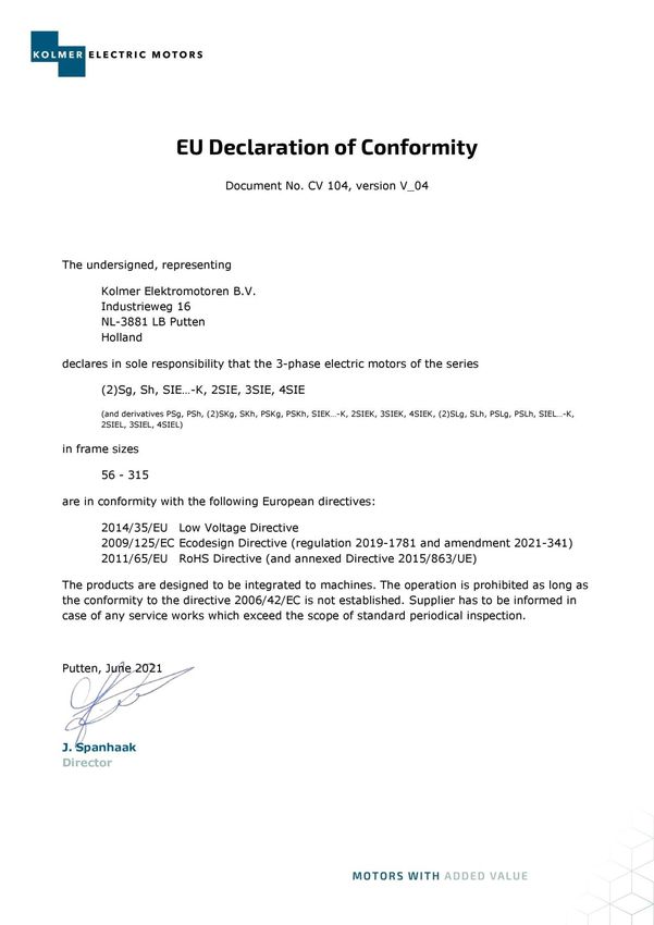
1.3. Declaration of Conformity

8
2. IEC 56-80 ITR/TR/1/99, 2016-04 2.1. Technical description The squirrel-cage induction motors of frame size 56, 63, 71, 80 are low power, enclosed motors. In standard execution they are in IP 55 degree of protection (on special request IP 56, IP 65 or IP 66). They are intended for continuous running S1 (other type of running - according to arrangements). Parts of motor housing are made of aluminum alloy EN AC-44300 (AK 11) apart from the fan cover which is made of steel sheet. In the terminal box there is a terminal board which is used for connecting the motor to the mains and the neutral terminal PE which is used for connecting the protective conductor “PE” or protective-neutral conductor “PEN” which is indispensable in protection by automatic disconnection of supply in systems TN, TT, IT. The terminal box is equipped with a gland M20x1,5 through which the power lead should de inserted and sealed. In single-phase motors the permanent capacitor made of metalized paper is connected in series with winding of auxiliary phase. It is also connected to terminals of the terminal board. Motors are intended to work in a horizontal position of the shaft. They can work in perpendicular position, with the shaft end downwards or upwards provided the axial load of the bearings is not too large and originates from the weight of a rotor, a pulley or toothed wheel, relatively light clutch or the fan which is fixed on the motor shaft. Maximal radial and axial forces which can act on the shaft end - on request. If motors are equipped with drain holes then condensation water should be drained in a horizontal position – after removing a rubber stopper. Maximal temperature of the environment, in which the motors operate, depends on the climatic execution and cannot be higher than: 313K (+ 40°C) for the temperate climate N/2, N/3 and the tropical humid climate TH/2, TH/3 318K (+ 45°C) for the marine climate MU/2 and MU/3 2.2. Operating conditions Squirrel cage induction motors series „g” and „h” frame size 56, 63, 71, 80, 90 are general destination products provided for driving various machines and devices. The motor housing, made in the degree of protection IP 54 (or IP 55, IP 56, IP 65, IP 66) protects the motor from being penetrated by a solid body or water in the range defined in Polish Standard PN. It is recommended to use a PN-EN60034-5. Draining of condensation water should be carried out every 12 months, while exploiting under difficult conditions every 3 months. Marine motors made according to the requirements of Polish Register of Shipping are manufactured in the minimum degree of protection IP 55. Direct-on starting is used in motors. They can operate when voltage deviations do not exceed ± 5% of the motor rated voltage. All of the rated data refer to the rated voltage. If voltage deviations exceed ±10% of the rated 9
voltage motors should not be started. This rule can be omitted only if motor has a suitable heat reserve for the specific application, after arrangement with Kolmer. Each motor must be protected against overload and short-circuit by protections selected by an user in accordance with Polish Standard PN-89/E-05012 and recommendations of Kolmer. Usage of neutral terminal depends on measure of protection against electric shock which is used in accordance with Standard HD 60364-4-41. Parts of driven device coupled to the motor shaft directly should be balanced dynamically with an accuracy of 5 mm, not less. 2.2.1. Activities before the installation of a motor Before you mount the motor to a motored device: 1. Check if the rotor turns freely 2. Check if parts of the device which is coupled to the motor shaft are balanced dynamically with the required accuracy 3. Put on parts of a motored device sliding or pushing them lightly without exerting pressure on bearings. Otherwise you will cause damage. At the same time the motor shaft should be supported on the non-drive end stiffly so that the pressure should not cause either damage of bearings or damage of a spring washer which cancels axial play of the rotor 4. After fixing the motor in a device check whether there is the minimal distance (14mm) between the fan cover and other parts, whether the holes in the cover are not stopped down ATTENTION! Access of cooling air to the motor housing cannot be made difficult. 2.2.2. Activities before the installation of a motor Three-phase motors a) made for basic voltage 230/400V can be connected: To the mains with line-to-line voltage: 3x 400V ±5% 50Hz ±2%, when the motor winding is star connected To the mains with line-to-line voltage: 3x 230V ±5% 50Hz ±2%, when the motor winding is delta connected b) Motors made for specific voltages can be connected to the mains of rated voltage U corresponding to the voltage marked on the rating plate of the motor UN, U=UN ±5% , f=fN ±2%. Three-phase motors are made as: single-speed with the pole number 2p = 2, 4, 6, 8 two-speed with the pole number: o 2p = 4/2 - single-winding 10
o 2p = 8/4 - single-winding o 2p = 8/6 - double-winding o 2p = 6/4 - double-winding o and with other number of poles - as requested. Three-phase general purpose induction motors can work with frequency converter. Selection of the frequency converter and the motor depends on the motor load, speed control range, ventilation and other requirements. Range of rotation speed of standard squirrel-cage induction motors can be regulate from 25Hz to 90Hz. In case of supplied motors with frequency converter: installing of the interference eliminating filters length of the supplying shielded cables should not exceed 50m carrier frequency should not exceed 5kHz deformation of the voltage (THD) should not exceed 10% power cables should be separated from the signal cables. Before you connect the motor check: 1. If the rated voltage of the motor corresponds to voltage of the mains (deviations of the voltage of the mains cannot exceed ± 5 % of the rated voltage) 2. If winding connections on the terminal board are consistent with a wiring diagram 3. If neutral earthing (N) and protective grounding (PE) of the motor is correct and firm 4. If the motor has the right overload protection (thermal protection recommended) 5. If the motor has the right protection against short circuit (a fuse or an electromagnetic breaker) 6. If resistance of the motor insulation in the cool state is not lower than 20 MOhm 7. If the direction of motor rotation is consistent with the direction of motored device rotation , in typical motors the direction is clockwise when you look from the shaft end 8. If the capacitor (in single-phase motors) is not damaged (that is, whether the capacitor cover is not damaged or if there are not any dents) ATTENTION! 1. In case of moistening (when the resistance of the motor insulation is lower than 20 MOhm) the motor should be dried in the temperature not higher than 353K (+ 80°C) 2. Neutral earthing of the motor must be made by connecting a neutral wire to a neutral terminal of the motor (N), and protective grounding (PE) to protective terminal which is placed on the motor housing 3. When the motor operates pay attention to how it works and disconnect the motor from the mains in following cases: Over-oscillation of the motor (excessive oscillation) Considerable decrease of rotational speed Overdue heating of the motor or bearings 11
2.3. Maintenance of the motor The motors should be subjected to periodical inspection and maintenance after 24 months of operation or after 20 000 hours of operation. Special - purpose motors should be subjected to periodical inspection and maintenance after 12 months of operation or after 20 000 hours of operation. During the inspection the following actions should be carried out: Visual inspection (the state of seals, screw joints, surface) as well as cleaning of the motor and protecting apparatus without disassembly, to the extent that the visual inspection does not reveal such necessity Measurement of the resistance of motor winding insulation Measurement of the effectiveness of neutral earthing or the resistance of protective grounding Measurement of the resistance of feed installation insulation, estimation of the noise level, motor smoothness Draining of condensation water by unplugging the rubber plug from a drain hole o In IP 55 execution it is situated in drive end bearing shield; o In IP 56, IP 65, IP 66 execution it is situated in both bearing shields: DE and NDE All the activities connected with disassembly, repair or assembly of the motor should be carried out by appropriately trained person, in case of electric strength test of the motor – by authorized person. 2.4. Acceptance test after inspection or repair After inspection and remounting the motor should be subjected to examinations: 1. To measure winding resistance, 2. To control if the connections are correct, 3. To measure insulation resistance in cool state, 4. To carry out a 2 hours’ no-load running test of the motor and if it is possible to carry out a test of a rated loaded motor. The test must be long enough for the motor temperature to stop rising in a visible way. The above researches must be conducted according to the EN 60043-1. 12
2.5. Storage Motors should be stored in dry airy containers free from gases, liquids and casting vapours which are harmful for the winding insulation and parts of the motor. Motors must not be kept in rooms where fertilizers, chlorinated lime, acids and chemical agents etc. are gathered. The temperature of the environment where motors are stored must not be lower than 278K (+ 5°C) and relative humidity must not exceed 70 %. Motors stored more than during a warranty period should be renovated, what includes: Outside cleaning of the motor Checking if bearings operate in a correct way and, if not, damaged bearings must be replaced Measurement of the winding insulation resistance (in cool state) and if it is lower than 20 MOhm motors must be dried in a temperature not higher than 353K (+80°C) The shaft end must be protected against corrosion by the layer of corrosion preventing grease or easily removed varnish. 2.6. Connection diagrams 13
14
3. IEC 90-180
 Edition 2

3.1. Specification and use
This section has been created for three-phase squirrel-cage single and dual speed induction
motors, with shaft height above the mounting feet’s surface of: 90, 100, 112, 132, 160, 180,
designed to drive various types of machines and appliances. The manual also describes special
motors designed to be mated to a frequency converter with an external cooling unit and
brakes. Motors are adapted for indoor and outdoor use.

Design characteristics

 Characteristic Standard execution Special execution

 Type of operation S1 S2, S3, S4, S6

 Insulation class F H

 Protection rating IP 55 IP 65

 Temperature range -20 to +40°C -40 to +120°C

 Installation height up to 1000 m above sea level up to 4000 m above sea level

 Relative humidity 95% -
 Frame material IEC 90, 100, 112 Aluminium Cast iron

 IEC 132 Cast iron Aluminium (IE3 only)

 IEC 160, 180 Cast iron

 Front shield/flanges IEC 90-180 Cast iron
 material

 End shield material IEC 90, 100 Aluminium Cast iron

 IEC 100-180 Cast iron

 Thermal protection PTC (IE2 and IE3) PTC, PT100, clixon

 Cooling system IC 411 Other methods

 Terminal board 6 9 or 12

 Greased bearings IEC 132-180

 Gripped bearing IEC 90 All sizes and versions

 IEC 100 Brake motors All sizes and versions

 IEC 112-180 Brake motors All sizes and versions
 1011, 2011, 3011, 3611

 Drain bolt Motor size 132-180 All sizes and versions

 Number of cable IEC 90-112 2 All sizes and versions
 inlets
 IEC 132-180 1 All sizes and versions

 Terminal box location Top Left or right side

 15
3.2. Transportation and storage CAUTION! When lifting drive units always use lifting handles designed for this purpose. Motors should be transported packaged, in roofed vehicles, avoiding sudden shocks and impact, secured against mechanical damage and humidity. Packaging should adequately protect the motor from mechanical damage during transport. When lifting the motor or moving it without the packaging, use the lifting eye bolt located at the top of the frame in the middle part of the motor. Do not attach the rope to motor elements which stick out, such as the terminal box, mounting feet, shaft neck, etc. The motor should not be lifted when it is attached to other equipment. Only the main lifting lugs or eyebolts of the motor should be used for lifting the motor. Lifting lugs for auxiliaries (e.g. brakes, separate cooling fans) or terminal boxes should not be used for lifting the motor. The motor should be stored in a storage space, where: Dust, fumes and acrid vapours and other agressive chemical fumes which can damage the isolation or the cover cannot enter Maximum relative humidity does not exceed 80 at 20°C In case of motors with heating or anti condensation elements, they can be plugged into mains Temperature of the surroundings is between -10°C and +40°C No vibrations occur It is important to protect processed surfaces of motors in storage from atmospheric impact, by covering them with thick grease or easily removable anti-corrosion paint. ATTENTION! After storing a motor for a period of three years, its bearings should be replaced for new ones, or greasing should be replaced. 3.3. Motor installation LIFE DANGER! Prior to starting any work on the motor, make sure that it is unplugged from the mains. 3.3.1. Inspecting the motor prior to the assembly Before starting the motor, check: Whether the motor complies with your order Whether the motor’s rated Voltage confirms with the network Voltage 16
Whether the motor hasn’t been damaged during transportation or storage Whether the motor’s rotor rotates freely (turn it manually) Whether the surrounding temperature in the location of the motor’s installation does not exceed +40°C, (for marine motors +45°C or +50°C, according tot he maritime association regulations) Whether free flow of cooling air, necessary for proper operation of the motor, will be provided. Minimal distance between the end of the motors frame and other elements: o For IEC 90: 15mm o For IEC 100, 112: 20mm o For IEC 132, 160, 180: 40mm Tightness of all mounting screws on the motor 3.3.2. Checking of the insulation resistance Inspection of the insulation’s condition should be done prior to starting the motor, if moistness of the winding is suspected, or after a lengthy standstill or storage period (about 6 months). Insulation resistance should be measured using 500V direct current. LIFE DANGER! During, and directly after measuring the insulation resistance, harmful voltage is present in the terminals, therefore it is forbidden to touch them. In order to remove the threat of electrocution, it is necessary to discharge the winding. The minimal value of the insulation resistance in regard to the frame or between phases in the temperature of 25°C ± 15°C for a new or repaired motor is 10MΩ. While the motor is in operation, the insulation resistance may drop, however, it cannot be below the critical insulation resistance value, which is a product of inter-wire supply voltage and constant coefficient 0.5MΩ/kV. In case of a motor powered by a frequency converter, the minimal value of the motor’s insulation resistance is 1 MΩ. During the measurement, the winding should be in operating temperature. An example of a motor powered from a 3 x 400V network: 0,4kV x 0,5MΩ/kV=0,2 MΩ. If the expected winding resistance falls below the level of the critical resistance value, the motor should be immediately taken out of service and the cause of the lowered resistance value - moistness, pollution, damage, etc - removed. After the repair or drying, the conditions of insulation should be checked again. During the drying process, create conditions necessary to remove moisture from the winding, i.e. at least, take off the cover of the terminal box in order to make the exchange of air with the interior of the motor possible. For motor sizes 132, 160 and 180, there is a possibility to drain the condensate by unscrewing the drain plugs installed in the bearing brackets. The recommended drying temperature is 60 to 80°C. The motor should be dried until insulation resistance reaches its minimal value (2-8h). 17
In case of motors with heating elements, drying can be performed by connecting them to the mains. Another method of drying is single-phase powering of two out of the three motor outlets with a voltage with a value of about 0.2 of the rated voltage. This way, the motor will not spin, and the value of the input current will be from 25% to 35% of rated current. Heating the motor’s winding using the heating elements or single-phase powering prevents the condensation of steam and can be done during the whole period of standstill. 3.3.3. Placing the geared pulley or half coupling on the motor’s shaft extension Prior to placing the geared pulley or the half coupling on the motor’s shaft extension: Remove any possible injury marks from the shaft extension Remove protective paint from the shaft extension Lightly cover the shaft extension with grease Clean anti-corrosion layer from the flange disc Placing the geared /wedged/ pulley or the half coupling should be done with the use of an appropriate tool, as shown in figure 3.1 – using the threaded centre hole of the shaft extension. Figure 3.1 If necessary, heat up the coupling hub or the pulley /belt, geared/ to about 80°C. In no special equipment is available, the heated up coupling or geared pulley can be hammered on using a suitable sleeve, simultaneously supporting the opposite shaft extension, so the force from the hits is transferred to the support, not the bearings. After putting the belt, wedged, geared pulley or half coupling on the shaft extension, secure it from sliding off the shaft using a screw with a washer, screwed in the threaded centre hole of the shaft extension. 18
3.3.4. Motor orientation Motor should be oriented in such a way so that it is structurally adapted as much as possible to have easy access for inspection and operations relating with its maintenance. Motor on mounting legs can be mounted directly on anchor bolts or on take-ups allowing for belt tension adjustment. When connecting the motor to the driven appliance using a coupling, particular attention needs to be given to the concentricity of shafts: the motor and of the driven machine’s shafts – as shown in fig. 3.2. For belt drives, it is recommended to use transmissions with wedge belts, which have: Smaller slide Quieter operation Lower belt tension Lower belt tension result in a lower risk of damaging motor’s bearing from the drive side. Correct assembly and appropriately balanced coupling element have a significant effect on the drive’s vibrations and quite operation. Correct setting Maximum permissible non-concentricity a= 0,25 mm (IEC 90-180) 0,1 mm (IEC 200-315) b= b2 - b1 = 0,1mm/ 200mm Figure 3.2 19
3.3.5. Connecting the motor to the mains ATTENTION! The earthing or the protective conductor should be connected to the terminal marked with the earthing symbol located in the terminal box or on the motor's frame. Minimal earthing or protective lead profiles: Live lead profile S [mm2] Earthing or protective conductor profile [mm2] S 25 S 25 S 50 25 S 50 0,5 S Each motor has a rating plate attached to its frame. This rating plate includes information such as: Supply voltage – permissible deviation ± 5% not requiring decreasing the power Supply voltage frequency – permissible deviation ± 2% not requiring decreasing the power Connection of the 3-phase winding in a star (Y)or a delta (Δ) Input current at rated load The box contains a terminal board with 3 or 6 terminals. Power cables should be led in to the terminal box through stuffing boxed or glands. The screwed in cable inlets should prevent water and dust from entering the terminal box during operation. Stuffing box throttle range is included in the below table. Gland size Throttle range in mm M12 3,5 – 7 M16 4,5 – 10 M20 7 – 13 M25 9 – 17 M32 11 – 21 M40 19 - 28 Power leads should have a cable tips. Torque values, with which the nuts and screws of the electric connections should be tightened, are listed in the below table. Detailed rules regarding installing electric motors are given in PN-E-05012. Thread M4 M5 M6 M8 M10 M12 M16 Torque value Min. 0.8 1.8 2.7 5.5 9 14 27 in Nm Max. 1.2 2.5 4 8 13 20 40 20
Direct (DOL) starting Each motor is adapted for direct starting. In case of a 3-terminal board, motor is designed for one voltage, which is indicated on the rating plate. Direct start can take place by plugging directly into the mains, after making sure that the inter-wire voltage of the mains is equal to the rated voltage of the connected motor. In case of a 6-terminal board, using the connectors supplied with the motor, create a correct phase match, meaning Y or Δ, and connect the power supply to the terminals in accordance to the connection diagram attached with the motor. An example: motor marked 230/400Y V can be connected in two ways, depending on the supply network: In a Δ connection if inter-wire voltage is 3 x 230V or In a Y connection if inter-wire voltage is 3 x 400V Indirect (0-Y-Δ) starting 0-Y-Δ start can take place only in motors with 6-cioma outlets from one winding, and supply voltage must be equal to the motor’s rated voltage in a Δ connection. Connectors should be removed from the terminal board. Indirect starting is used in order to limit the motor’s starting current and large drops of voltage in the mains as an effect of high starting voltage. Remember that the motor with a nominal connection in Δ has a 3 times smaller starting torque in an Y connection, that’s why the 0-Y-Δ start should be performed without load or with the lowest possible load. Start of the motor begins with the Y connection, and after achieving a stable rotational speed by the motor, switches to Δ. If the motor cannot start in the Y connection, instead of using the 0-Y-Δ, use the direct start method. If start is still impossible, reanalyse the starting conditions and motor selection. An example: starting a motor marked 400Δ/690Y or 400ΔV powered by 3 x 400V network: Connection in Y – operation 10s Switch to Δ – constant operation, Put the motor under load Detailed regulations regarding installing electric motors are given in PN-E-05102. Direction of the motor’s rotation The standard direction of rotation is clockwise, as seen from the shaft extension’s drive side, when the power supply phases L1, L2 L3 are connected according to the diagram attached with the motor. In order to change the rotation direction, change any two power supply phases. 21
Winding thermal protection – included upon request Two types of thermal protection are used in motors: Thermal bimetal PTC-resistor Terminals of PTC-resistor temperature sensors should be connected with the appropriate input terminals on the resistance relay, and terminals of thermal bimetal NC temperature sensors can be connected directly to the motor’s safety circuit. Motors, in which the stator’s winding has buried thermal protection, have finishing lead of the beginnings and ends of temperature sensors, which are connected in series, connected to an additional terminal block, in the terminal boxes. Thermocontact sensors Three thermocontacts are located in the motor’s winding, connected in series (figure 3.3). Each one is placed in a different phase. Figure 3.3 An example of the power supply system of a motor with thermal protection using thermocontacts is presented in drawing 3.4a. Figure 3.4 22
Technical parameters of thermocontact S01.150.05: contact opening temperature - 150ºC°C ±5ºC°C rated current - 250V, 50 ÷ 60Hz load: 2,5A at cosφ=1 1,6A at cosφ=0,6 max load – 40.A at cosφ=1 contact system – normally closed electric resistance of the insulation – 2.0kV resistance - 4000 Ω rated current - ≤2,5V- max current – 30V- electric resistance of the insulation – 2.5kV 23
Anti-condensation heaters Anti-condensation heaters are used in cases of a risk of steam condensation inside the motor. The effect of steam condensation can take place during long-term standstill of a cold motor in humid air. In such a case, turn on the heaters for a few hours prior to starting the motor, and after drying check the insulation resistance value as described in chapter 3.3.2 or keep the heaters turned on during the whole standstill period. For motor sizes 132, 160 and 180, there is a possibility to drain the condensate by unscrewing the drain plugs installed in the bearing brackets. Do not power the heaters while the motor is in operation. Standard heaters: 2 heaters, 25W each, running on 230V current with three leads. When connected parallel, the power supply current may amount to 200-240V, and connecting in series allows for powering the heaters with 400-480V current. 3.4. Operation and use of the electric motor 3.4.1. Operational safety regulations In order to avoid unfortunate accidents while operating the motors, it is important to follow these rules: electric motor operators should be familiar with the operational safety regulations regarding electric devices and their operation, the motor cannot in any case be in operation without a functional earthing. The quality of earthing or neutralization should be checked periodically for the reason that contacts may loosen or get corroded. Do not perform any repairs while the motor is in operation; maintenance, inspections or repairs of the motor can be performed only on a motor disconnected from the mains; the motor should be earthed or neutralized in accordance with current regulations in this regard. The quality of earthing (neutralization) should be inspected periodically; the motor cannot be operated without the cover of the external fan and without the cover of the coupling or the belt, fan or gear transmission, with elements leading current exposed, each location where the electric motion takes place should be equipped with a fire extinguisher filled with non-conducting extinguishing agent. safety devices preventing accidents from occurring should be present in the location of the installation, in accordance with local safety regulations. 24
3.4.2. Motor start and use Prior to starting the previously prepared motor, as described in chapter 3.3, check the functionality of control circuit on an unloaded motor. Check whether the change of rotational speed takes place and whether the motor is spinning in the correct direction. Motor can be started by: connecting to the mains directly, an indirect 0-Y-Δ start. Both methods are described in details in chapter 3.3.5. The maximum number of consecutive starts is dependent on the degree of starting difficulty and limited by the maximum temperature increase for the given heat resistance class of insulation. While the motor is in operation, systematically check the correctness of such operations as: the state of motor heating up on its frame – in some types of motors, the temperature increase of the frame can reach as much as 70K; correct functioning of bearings – which is manifested by quiet, even humming, whether there are no excessive vibrations of the motor, the condition of the motor’s coupling with the powered machine, current input shouldn’t exceed the nominal value. Normal, stable work can take place with current fluctuation not exceeding ±5% of the rated current and ±2% of the rated frequency. The motor should be turned off immediately in case of: smoke or fire, etc. coming out of the motor or the installation; excessive heating of the motor; significant decrease of rotational speed, damaging of the external fan; damaging of the driven machine; when, for any reason, further work of the motor and the driven machine is a threat to the surroundings. Switching on the motor and the appliance again can take place after all defects have been removed. 3.4.3. Mating the motor to a frequency converter Standard motors have an insulation system making it possible to be powered through frequency converters. These converters allow for adjusting the motor's rotational speed. Do not exceed the maximum rotational speeds of the motor listed in the following chart: Motor size 2p=2 2p=4 2p=6 2p=8 rev/min 90 112 5200 3600 2400 2000 132 180 4500 2700 2400 2000 25
Adjustment of rotational speed, depending on the load torque, can take place only in scope presented in the figure 3.6 left, and the maximum load torque of induction motors with external cooling, depending on the frequency of supplied current, is presented in figure 3.6 right. Operation in orange field is dependent on kind and settings of frequency converter. Figure 3.6 – Load torque Analysing the formula: 9550 ∗ [ ] [ ] = [ ] notice that the increase of rotational speed, while maintaining a constant torque, must be accompanied by an increase of power. With speeds exceeding the rated speed, the increase of power would cause an increase of the current drawn by the motor, which causes motor overheating. For this reason, in rotational speed higher than the rated speed, the load torque on the shaft needs to be lowered. While operating the motor in rotational speed higher than the rated speed, pay attention to the current drawn by the motor, and make sure that it is not higher than the rated current. While the motor is operated in speeds higher that the rated speed, the level of noise and vibrations increases, and the life span of bearings can be shorter. Attention: do not exceed the rotational speed listed in chart. A method of eliminating these unfavourable effects can be: using dU/dt filters, which smooth out the rate of output voltage, blocking the frequencies in the inverter, in which the unfavourable effects take place, change of the carrier frequency (transistor keying), adjusting other inverter parameters. The ratio of the output voltage to the frequency converter's output frequency, in the range up to the rated frequency, is constant, which is a condition of achieving constant torque on the motor's shaft. Above the rated frequency, the voltage value is constant, which results from the voltage value of the converter's power supply. A motor, whose the rated voltage when connected in a star is equal to the rated voltage of the frequency converter, can be connected in a delta. 26
Its rated voltage will now be

 ≈ 0,577 ∗
 √3

This will make it possible to extend the range of operation with a rated torque to 87 Hz. The
new value of the motor's rated voltage should be entered into the frequency converter.

Attention: When making the connections described above, it is recommended to
consult with the supplier of the converter in regard to the new frequency converter
settings.

An example: Having a 230∆/400Y motor, connected in a star and a frequency converter with
output voltage ≤ 400 (ratio U/f=8), we can connect the motor in a delta (Un=230V)
and set this parameter in the converter (U/f=4.6). This way the adjustment range on the
motor's shaft, with a constant torque, increases to 87 Hz.

For example:

 Rated voltage of motor Rated frequency Rated current Rated output Maximal output

 400V Y (U/f=8) 50Hz 6,2A 3,0kW 3,0kW

 230V ∆ (U/f=4,6) 50Hz 10,7A 3,0kW 5,2kW (87Hz)

Withstand voltage stress of insulation

Motors up to 400V AC have insulating system compatible with standard IEC TS 60034-17,
resistant for voltage impulses 1,35kV at the impulse rise time ≥0,8µs. When using converters
without any reduction of voltage impulses such motors are suitable for drive systems only up
to 400V AC supply voltage within a restricted range of cable length. When using filtering
devices, such motors can be used for drive systems up to 690V supply voltage and without
limits of cable length.

Recommended is using filters on inverter output, which eliminate considerably problems with
overvoltage, acoustic effects, reduce current ripples. Filters protect motor isolation and
elongate time of using the motors.

 27
3.4.4. Defects in the work of a motor and their removal
Defects, which can be the reason of most frequent motor malfunctions, are listed in the
following chart:

 Defect Cause Solution

 Motor not moving or moves Motor overload Reduce the load
 heavily when idling
 Incorrect power supply Check the voltage of the terminals of
 the power supply, cable connection
 and the setting of the frequency
 converter; eliminate the cause

 Incorrect connection system Check the connection according to the
 diagram supplied with the engine

 Rotor damage Check if the bars or rings are
 damaged

 A short circuit in the motor’s winding or Eliminate the short circuit, the
 incorrect winding connection connection wrong or rewind the motor

 Blown fuses Replace the fuses with others of the
 same type and with suitable nominal
 values

 Automatic switch-off caused by Check the starter settings
 overloading

 Motor stalls One of the phases may be open Check if there is a phase in the lines
 interrupted

 Bad motor selection Change the engine type or size.
 Contact the supplier or manufacturer
 Overload Reduce the load

 Low voltage Check whether the voltage has been
 respected indicated on the plate.
 Check the connection

 Open power supply or control circuit Blown fuses, check load relay, stator
 and control keys

 Motor braking doesn’t take The brake’s air gap has exceeded its Adjust the air gap
 place despite switching off the maximum value
 power (regard motors with a
 brake) Power supply voltage too low Increase the supply voltage

 Opening in the power supply circuit Check and rectify the fault

 Opening in the electromagnet coil. Replace the electromagnet of the
 brake

28
Defect Cause Solution

Motor moves, then stops Power supply failure Check for a loose connection in the
 power supply line, fuses and control.

Motor does not reach the given Bad motor selection Contact the device’s supplier or
speed designer in order to determine an
 appropriate motor selection

 Voltage on the motor’s terminals is too Check whether the cables have an
 low, caused by a voltage drop in the appropriate size
 power supply cables.

 Incorrect power supply Check the voltage of the power cable
 terminals, check the power lead
 connection, check the setting on the
 frequency converter – remove the
 cause.

 Initial motor load is too high Check the rated initial load value of
 the motor

 A short circuit in the stator’s winding or Find and remove the short circuit
 a short circuit to the frame (to the (rewind the motor)
 ground)

 Cracked rotor bar or loose rotor Check for cracks near the ring. In
 case of frequent repairs, a new rotor
 may be needed

Overheating the motor (with a Motor overloaded Decrease the load
brake)
 Incorrect power supply Check the voltage of the power cable
 terminals, check the power lead
 connection, check the settings on the
 frequency converter – remove the
 cause
 A short circuit in the stator’s winding or Find and remove the short circuit
 a short circuit to the frame (to the (rewind the motor)
 ground)

 A break in the motor’s connection or Find and remove the break
 winding

 Incorrect power supply connection Connect the motor according to the
 diagram

 Too many starts per hour Increase the intervals in the motor
 operation, eventually decrease the
 number of switching’s

 Ventilation openings in the ventilator’s Clean the ventilation openings and
 or console’s cover may be blocked with check for the continuity of the air flow
 dirt, preventing correct motor from the motor.
 ventilation

 The gap between the core and the Remove any dirt and adjust
 shifted brake armature is higher than
 0.06mm in places

 29
Defect Cause Solution

Overheating the motor (with a Axial run-out of the brake lock’s front in Adjust the perpendicularity of the lock
brake) relation to the shaft’s axis is higher in relation to the shaft’s axis through
 than 0.05mm assembly or machining

 Brake power supply voltage too low Increase the power supply voltage

 Small, obstructed flow of air cooling the Improve brake cooling
 brake

 Brake’s operation too intense Decrease the number of switches per
 hour

Drop the braking torque in the The brake’s air gap has exceeded its Adjust the gap
brake (regards motors with a maximum value
brake)
 Brake pad lining worn out Replace the brake disk

 Brake’s friction surface polluted Clean, replace the greasy brake disk
 Damaged brake springs Replace the springs

Current intensity asymmetry in Asymmetry of the power supply voltage Check and remove the cause of the
the power lead power supply voltage asymmetry

 A short circuit in the stator’s winding or Find and remove the short circuit
 a short circuit to the frame (to the (rewind the motor)
 ground)

 A break in the motor’s connection or Find and remove the break
 winding

 Damage on the rotor cage Replace the rotor
Motor takes too long to gain Overloading Decrease the load
speed and/or draws too much
current Low voltage during starting Check whether the leads have an
 appropriate size

 Incorrect convertor settings Correct the settings

 Squirrel-cage rotor damaged Replace the rotor for a new one

 The voltage used is too low Contact the power supply company in
 order to increase the power level.
Incorrect direction of rotation Incorrect phase order Reverse the connections in the motor
 or on the switchboard

Overcurrent releases are The rotor or the ventilator seizes up Find and remove the mechanical
activated during the motor’s damage(rotor, pulley, coupling,
start ventilator, and carefully balance)

 A short circuit with the frame (the Find and remove the short circuit
 ground) (rewind the motor)

 A break in the motor’s connection or Find and remove the break
 winding

 Incorrect connection system Connect the motor correctly
Rate of rotation drop when Motor overloaded Decrease the load
under load (slip increases)
 Incorrect power supply Check the voltage of the power cable
 terminals, check the power load
 connection, check the setting on the
 frequency converter – remove the
 cause

 A short circuit in the stator’s winding or Fin and remove the short circuit
 a short circuit to the frame (to the (rewind the motor)
 ground)

30
Defect Cause Solution

Rate of rotation drop when A break in the motor’s connection or Find and remove the break
under load (slip increases) winding

 Incorrect connection system Connect the motor correctly

 Single-phase power supply Check the voltage of the power cable
 terminals, check the power lead
 connection

Overloaded thermal release Motor overloaded Decrease the load
turn the motor off during
operation Incorrect power supply Check the voltage of the power cable
 terminals, check the power lead
 connection, check the setting on the
 frequency converter – remove the
 cause

 Rotor damage Look for cracked bard or end rings

 A short circuit in the motor’s winding or Remove the short circuit, remove the
 incorrect winding connection bad connection or rewind the motor

 A break in the motor’s connection or Find and remove the break
 winding

 Incorrect connection system Connect the motor correctly

 Incorrect overload range setting in the Set the overload protection correctly
 thermal release

 Single-phase power supply Check the voltage of the power cable
 terminals, check the power lead
 connection, check the setting on the
 frequency converter – remove the
 cause

Motor vibrates Motor baldy aligned Re-align

 Weak mounting Enforce the base

 Unbalanced coupling Balance the coupling

 Driven appliance unbalanced Balance the driven appliance

 Bearings damaged Replace the bearing

 Unaligned bearings Re-align correctly
 Displaced balance weights Balance the motor

 Unbalanced motor and coupling unit Balance the unit

 Multiphase motor operates in a single Check whether the motor has an open
 phase circuit

 Excessive axial looseness Adjust the bearing or add a washer

Grinding The ventilator rubs against the cover Eliminate the friction

 The fan is hitting the cover Clean the fan and the cover, check
 the fan’s mounting on the shaft

 Looseness on the base plate. Tighten the clamping screws

Noisy operation Uneven air gap Check and correct the bracket or
 bearing mounting

 Spinning parts not balanced Find and remove the mechanical
 damage (rotor, pulley coupling,
 ventilator and carefully balance)

 31
Defect Cause Solution

 Noisy operation Belt tension too high Adjust the motor orientation and belt
 tension

 Incorrect coupling of the motor with the Replace the bearings. Adjust the
 driven machine motor orientation and belt tension

 Brake buzzing while switching A break in the brake’s electromagnet Replace the electromagnet
 the motor off circuit

 Break in the lead supplying power to Remove the damage
 the brake

 Brake’s air gap has exceeded its Adjust the gap
 maximum value

 Power supply voltage too low Increase the voltage

 Bearings heat up Bent or skipping shaft Straighten or replace the shaft
 Belt tension too high Decrease the belt tension

 Pulley too far Move the pulley closer to the motor’s
 bearings

 Pulley diameter too low Use larger pulleys

 Non-coaxiality Fix by aligning the drive again

 Low amount of grease in motors with Provide an appropriate grease quality
 greased bearings in the bearings

 Grease polluted or used up Replace the bearing or if possible,
 clean them and use new grease

 Too much grease Decrease the amount of grease,
 bearing should not be filled more than
 half way

 Bearing overloaded Check the alignment, side thrust and
 end thrust

 Cracked bearing balls or course Replace the bearing, accurately clean
 channels the cover first

 Motor seizes up Bearings damaged Replace the bearings
 Screw mouthing the disk to the frame is Tighten all clamping screws
 loosened

3.5. Motor maintenance
In order to maintain the motor in full technical efficiency, it is necessary to remove all defects
noticed during operation on an ongoing basis.

Regardless of the above, every working motor should be subjected to periodic maintenance
inspections. Time periods between maintenances, running and major repairs, are dependent
on the conditions of motor’s work.

 CAUTION!

 In order to attempt any type of work related with the motor or its elements, especially prior
 to taking off protective covers, prior to directly touching moving parts or parts which can be
 under current, unplug the motor and all additional and support circuits from the mains.

32
3.5.1. Periodic inspections Customary time periods are as follows: running inspection every 6 months (for dust-laden room, every 3 months) main inspection – once every 30 months. Running inspections – performed at the location of motor's installation, without a disassembly. This type of inspection can reveal a need to subject the motor to a main inspection. Running inspections include the following Main inspections – include the following operations: operations: cleaning the motor and a visual inspection, disassembly of the motor, measuring the insulation resistance of the winding; stator inspection, examining the condition of power cables and the inspection of the rotor, earthing cable; checking the tightness of all mounting and contact inspection of bearings and bearing chambers; screws; removal of condensate in motors featuring drain plugs measurement of insulation resistance of the winding; in the disks Checking the level of motor vibrations inspection of the starting and protective devices. Replacement of grease AFTER A MAIN INSPECTION AND ANY EVENTUAL REPAIRS OF THE MOTOR'S WINDING, CHECK THE CONDITION OF THE WINDING'S INSULATION Additionally, in motors with brakes, inspect the brake elements. A detailed description of the brakes is included in chapter 5. In case of a large number of switchings, inspect the brakes more often than every 6 months. All defects noticed during the inspection should be removed, and worn out parts replaced with new ones. It is recommended to renew the protective layers. 3.5.2. Sizes and types of bearings Size and type of bearings used in different types of motors: 2SIE(K, L) 90 - 6205-2Z-C3 2SIE(K, L) 100 - 6206-2Z-C3 2SIE(K, L) 112 - 6306-2Z-C3 2SIE(K, L) 132 - 6308-2Z-C3 2SIE(K, L)g 160 - 6309-2Z-C3 2SIE(K, L)g 180 - 6311-2Z-C3 33
3.5.3. Greased the bearings
Bearings closed on both sides / type 2Z/ are filled with grease by the manufacturer which lasts
for their whole life span. The life span of standard bearings is 25.000 hours.

After the expiration of the motor’s warranty it is recommended to replace the bearings for new
ones.

Bearings in motors with buried grease nipples in bearing brackets (figure 3.7) should be
greased periodically. Greasing periods, type and amount of grease are listed in the following
chart:

 Motor size Amount of refilled Grease refilling period [h] Grease type
 grease [g]
 n≤1500 rpm 3000rpm

 90 4 2500 1500

 100 5 2500 1500

 112 7 2500 1500
 132 10 1500 1000

 160 12 1500 1000

 180 17 1500 1000

 Figure 3.7

34
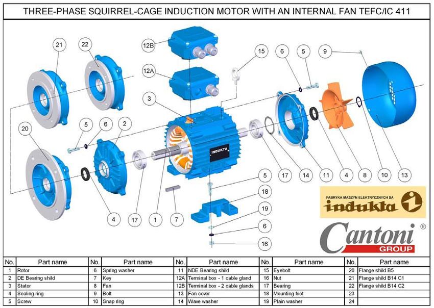
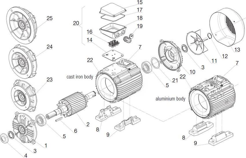
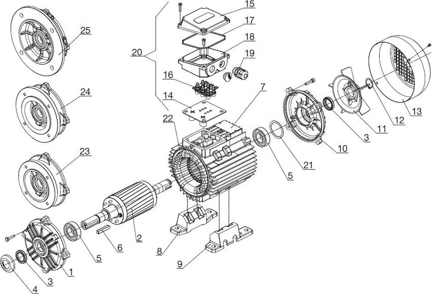
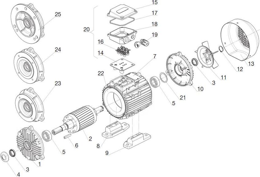
3.5.4. Disassembly and assembly of the motor By principle, motor disassembly should take place outside the place of its operation, in a specially prepared location. Tools required include a regular set of assembly tools and instruments. Prior to a correct disassembly, take off the motor pulley or the half coupling using a turnbuckle (fig. 3.8), remove the key (7) from the shaft extension, unscrew 4 screws (5) and remove the ventilator cover (13). After unscrewing 4 screws (5) which mount the bearing brackets “P”, carefully remove the rotor (1) with the bearing brackets “P” (11) and the ventilator (8) from the stator, without damaging the winding. If it is necessary, or when replacing the grease, remove both bearings (17) using a turnbuckle. Prior to removing the “P” bearing (), it is necessary to: Figure 3.8 remove the spring clip mounting the ventilator (10) and take off the ventilator (8) from the rotor’s shaft along with the key, using a turnbuckle; remove the “P” bearing bracket (11) from the rotor’s shaft (1). After completing these steps, remove the “P” bearing (17) using a turnbuckle. 35
Attention: For motors with a gripped bearing fig. 9 and 10, (also regards vertical motors), prior to the disassembly of the bearing it is necessary to: remove 3 screws mounting the bearing cover (4) and remove the rotor’s spring clip (3) (this also regards motors with a closed bearing chamber - see fig. 3.9) remove the spring clip in the bearing brackets (3) and rotor (4) (this also regards motors with an open bearing chamber – see fig. 3.10). Figure 3.9 Figure 3.10 36
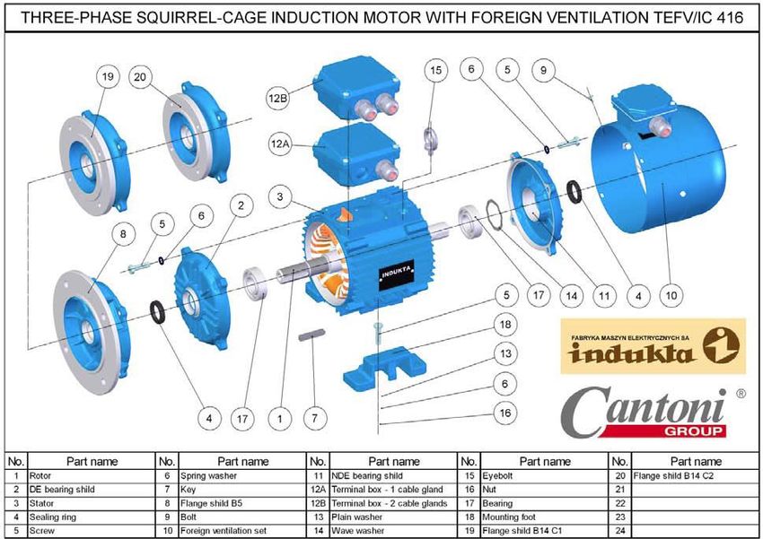
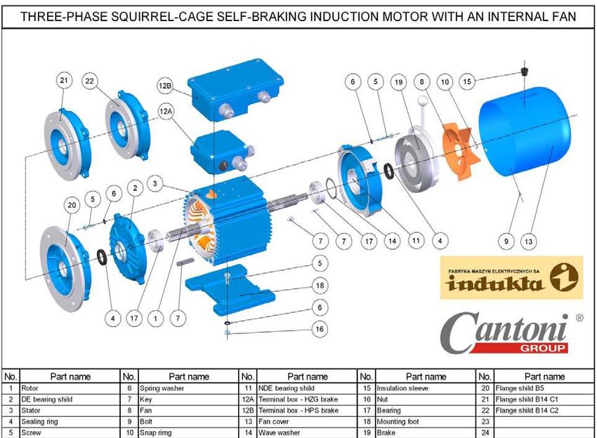
In case of a motor with a brake, prior to the disassembly of the motor it is necessary to
disassemble the brake (19).

In case of motors with an external ventilation system, external ventilation (10) is disassembled
along with the cover.

 37
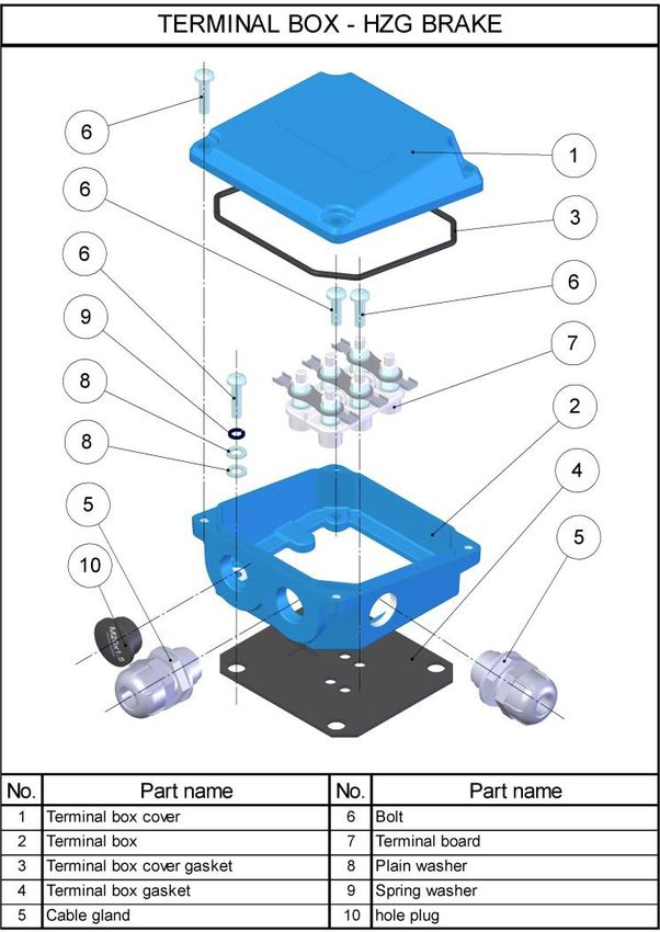
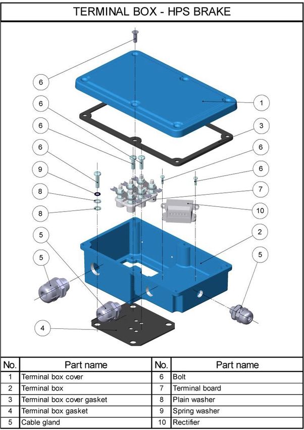
Disassembly of the motor’s terminal box is done in accordance with the below drawing. Depending on the type of Motor assembly should be done in reverse order. After a correct assembly, the rotor should freely turn when spinning the shaft neck manually. Disassembly of the motor’s terminal box is done in accordance with the below drawing. Depending on the type of motor, following terminal box settings are available: version with an HPS brake version with an HZG brake 38
3.6. Standard motor terminal connection diagrams

 39
ATTENTION!

Do not supply power to the external cooling or the brake using the frequency converter.

40
41
4. IEC 200-315 D4-034.190, issue III 4.1. Specification 4.1.1. General information Motors with parameters according to catalogue card satisfy requirements of the standard IEC 60034-1 and IEC 60034-30, efficiency class IE2 - (2SIE series) and IE3 - (3SIE series). Available motor options: on feet – mechanical sizes 200¸315 - type marking (2,3)SIE; flanged – mechanical sizes 200¸315 - type marking (2,3)SIEK; on feet with flange – mechanical size 200¸315 - type marking (2,3)SIEL. 4.1.2. Operating conditions Cyclic voltage variation: ± 5% Ambient temperature: -30°C up to + 40°C Relative humidity of air at 25°C: 100% Shaft axis inclination to level: 0°¸ 90° Operation type: S1 /continuous operation/ Motor installation altitude: up to 1000m above sea level 4.1.3. Protection rating Motors in basic version have protection rating IP55 as per IEC 60034-5. Higher protection rating (IP65, IP66) is available on demand. 4.1.4. Housing Motor housing (frame, bearing disks) and terminal box are made of grey cast iron. Ventilator housing is made of steel sheet. Air inlet is made as a grating sized so as to ensure protection rating IP20 4.1.5. Winding isulation Stator winding and employed insulating materials are in insulation class F. On demand motors are available in class H. Thermal protection built-in in stator winding: PTC (thermistors). Rotor cage is cast of aluminium. Version on demand: Pt100 thermoresistors built-in in winding; heating elements (protecting motor interior against occurrence of condensate during standstill). 42
You can also read