Simplifying the Design of Bigger, Higher Resolution Automotive Displays - By Szu-Kang Hsien, Executive Business Manager, Automotive Business Unit
←
→
Page content transcription
If your browser does not render page correctly, please read the page content below
Simplifying the Design of Bigger, Higher
Resolution Automotive Displays
By Szu-Kang Hsien, Executive Business Manager, Automotive Business Unit

January 2019
Abstract
Much like living room TV screens, automotive
displays are getting bigger and delivering higher
quality resolution. Infotainment and instrument
cluster systems are driving this trend. Delivering
the performance expected by consumers calls for
compact electronic components that support low-
temperature polysilicon process (LTPS) panels,
address electromagnetic interference (EMI) concerns,
and provide the dimming capability needed for better
readability. This paper discusses the challenges
of designing bigger, higher resolution automotive
displays and how light-emitting diode (LED) backlight
driver technology can help simplify the process.

www.maximintegrated.com                                 2 of 7
Introduction
Enabling High-Performance, High-Definition Displays
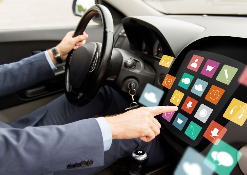
When you step inside a new car of them in tomorrow’s vehicles, especially
today—especially an electric or hybrid as the industry progresses toward Level
vehicle—you’ll be greeted with large, 5 fully autonomous vehicles. Already,
razor-sharp screens displaying everything many cars have up to eight displays inside
from vehicle performance metrics to for features like the instrument cluster,
blind-spot views to your music playlist. the center information display (CID),
You currently control them via touch or the smart back mirror, heads-up display
voice and in the future, they’ll support (HUD), rear seat mount on the head
By 2023, cars new interactive capabilities, much in the support, and rear seat mount on the roof.
way that smartphones and tablets are According to IHS Market, by 2025, nearly
could have evolving. Connected cars provide safety half a million side-view camera display
functions as well as a more engaging ride. systems will replace side mirrors each year
displays topping
While displays larger than 8 inches are in new vehicles1. So, cars with up to 10
34 inches quite common now, analysts project that displays inside are coming. Figure 1 shows
by 2023, we’ll begin to see screen sizes the rate of growth of the automotive
greater than 34 inches inside our cars. display market over the next few years.
Screens that are greater than 10 inches will
In this paper, we’ll highlight key design
show a variety of different content, with
challenges associated with designing
touch- or mouse-based controls and even
bigger, higher resolution displays and
split-screen formats. On the resolution
discuss what to look for in LED backlight
front, 4K and, eventually, 8K will become
driver technology to overcome these
standard. Not only are screens getting
challenges.
larger and sharper, there will also be more
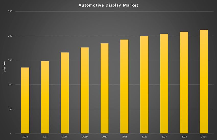
3 of 7 www.maximintegrated.comFigure 1. The market for automotive displays is expected to grow at a 15% CAGR from 2017 to 2022.
Source: Strategy Analytics and author projections.
Achieving Optimal signal on the source line is written (added,
recorded) on the liquid-crystal capacitor.
Display Performance The source line signals the capacitor (in
Automotive displays, particularly the the form of voltage) in order to control
center stack and the instrument cluster, the deflection angle of the liquid-crystal
are commonly based on thin-film molecule to realize the display. When
transistor (TFT) liquid crystal display necessary, the holding capacitor is
(LCD) technology (See Figure 2). In 2017, connected in parallel with the liquid-
TFT LCD displays had a 60% share of crystal capacitor to improve its retention
the market, according to the Automotive characteristics. The gate line controls the
Display Market Tracker. Inside these types TFT ON and OFF. When the switch is off,
of displays are tiny switching transistors the switch prevents the signal from leaking
and capacitors that are arranged in a out of the liquid-crystal capacitor. In this
matrix pattern on the display glass. The section of the paper, we’ll highlight some
action of the TFT element is similar to a of the key challenges that can hamper
switch, and the role of the liquid-crystal display performance and present some
element is similar to that of a capacitor; ways to overcome these challenges.
i.e., the switch of the ON/OFF updates/
holds the stored voltage values of the
capacitor. When the switches turn on, the
www.maximintegrated.com 4 of 7The larger and more uniform grains of
polysilicon (poly-Si) allow electrons to
GATE/ROW flow 100x faster than they do through
TFT
the random-sized grains of amorphous
silicon (a-Si), enabling higher resolutions
C PIXEL and higher speed. Supporting these
VCOM faster responding panels, however, calls
SOURCE/COLUMN
for both a positive analog supply voltage
(PAVDD) and a negative analog supply
Figure 2. TTFT-LCD drive principle. voltage (NAVDD) as well as regulated
Screen Size and Current Levels output voltages (VGH and VGL) to bias
the TFT. While PAVDD and NAVDD aren’t
The larger the screen size, the more requirements for LTPS panels, the market
current is required to drive these higher is trending in this direction.
voltages. At these levels, the timing
An ideal LED controller (TCON) is unable to provide Dimming Capabilities
the currents needed. In smaller screens,
driver is small and Dimming capabilities are a consideration
the TCON can easily meet current supply that affects display performance. When a
capable of driving requirements. For displays over eight vehicle is traveling through a very bright
inches, a separate TFT bias or PMIC
high voltages is needed. As a result, an LED driver
and sunny environment, the displays
will require more current to provide the
integrating TFT bias can save customers screen visibility that the driver will need.
board size and lower the BOM cost. For Conversely, when the car is going through
displays in the range of 8 to 14 inches, a dark stretch, like through a tunnel or at
LEDs 10-11 in series with 4 in parallel and night without much moonlight, that high
up to 130mA per channel are usually level of current won’t be ideal because it
needed. Thus, an LED driver with four will result in screens that are too bright. In
channels, output maximum of 52V, and these cases, the current levels will need to
up to 150mA per channel, is ideal for this be adjusted down so that the displays can
application. become as dim as possible while still being
Supporting LTPS Panels readable for the driver. An LED driver with
a high dimming ratio can address this
Another display trend that is creating challenge.
a new challenge is the move from
amorphous silicon to LTPS panels. With Mitigating EMI
amorphous silicon, the grain size in the
EMI is an ever-present challenge for many
TFT technology is quite small, so the
types of electronics. For vehicles, there are
electrons moving through these grains
both internal as well as external sources
will move through slowly. LTPS, on the
of RF electrical noise that can hamper
other hand, has a larger grain size, which
performance and reliability of the displays
increases mobility of the electrons and
in advanced driver assistance systems
allows for faster responding panels.
5 of 7 www.maximintegrated.com(ADAS) and infotainment applications. Available in a 6mm × 6mm 40-pin
Inside today’s vehicles, there are so TQFN package, the MAX20069 is ideal
many electronic components in various for displays 8 to 12 inches and beyond,
subsystems, all placed close to one featuring:
another in a relatively confined space, that
• Integrated TFT bias and LED
RF electrical noise is bound to be a factor.
backlight driver to support bigger
AM/FM radio interference is one of the
panels, reducing solution size and
more obvious hindrances. Automotive
saving bill of materials (BOM) cost
OEMs are responsible for mitigating
excessive EMI from their electronic • PAVDD, NAVDD, VGON, and VGOFF
systems. CISPR 25 from the International to support LTPS panels
Special Committee on Radio Interference • A 10,000:1 pulse-width modulation
provides a standard for conducted and dimming ratio at 200Hz to support
radiated emissions in vehicles. Switching high dimming ratio needs
at 2.2MHz, spread-spectrum frequency MAX20069
modulation, phase-shifting capabilities, • Spread-spectrum on the LED driver
and TFT, phase-shift dimming of LED
supports bigger
gate slew rate control as well as hybrid
dimming can reduce EMI. strings, and selectable switching panels in a
frequency to mitigate EMI
Flexible Sequencing reduced solution
• Flexible resistor-programmable
Some OEMs use displays from different sequencing to support different size
panel makers in their vehicles. This TCON and panel makers
can present challenges from a timing
• Boost/SEPIC technology to serve
standpoint. Since each panel would likely
different LEDs in a series
have different power rails to turn on first,
you would need to ensure that you can The MAX20069 can enable functional
easily manage the sequence in which each safety via on-board diagnostics through
of the displays powers on. Any TFT bias IC I2C. When the IC detects a failure in
which has flexible sequencing can be used a string in the LED, it can alert the
across all panel makers’ displays. microcontroller of the location of the
failure via I2C. The microcontroller
Automotive TFT Bias can then either increase the current
of the other channels on the LED or, if
with LED Driver for High- appropriate, send the driver an alert of a
Performance Displays malfunction in, say, the instrument cluster.
Figure 3 provides an example sub-system
Maxim has an automotive-grade power IC
block diagram. MAX20069 can also be
that brings together a 4-channel, 150mA
used in standalone mode if the application
LED backlight driver and a 4-output
doesn’t require I2C.
TFT-LCD bias.
www.maximintegrated.com 6 of 7GAMMA
AVDD BUFFER
MAX9669
2.5V TO 5V
VGH, VGL
SOURCE DRIVER
/(0*1,&2*"3,*
LED BIAS
I2C MAX16927/8/9
MAX17075 TIMING
!"#"$%&
CONTROLLER
MAX20067 RST '($)*(++,* SHIFT
/4"5)
LEVEL
SHIFTER REGISTERYou can also read