Snap-through transition of buckled graphene membranes for memcapacitor applications
←
→
Page content transcription
If your browser does not render page correctly, please read the page content below
www.nature.com/scientificreports
OPEN Snap-through transition of
buckled graphene membranes for
memcapacitor applications
Received: 19 September 2017 Ruslan D. Yamaletdinov1,2, Oleg V. Ivakhnenko3,4, Olga V. Sedelnikova1,2,
Accepted: 31 January 2018 Sergey N. Shevchenko 3,4 & Yuriy V. Pershin1,5
Published: xx xx xxxx
Using computational and theoretical approaches, we investigate the snap-through transition of buckled
graphene membranes. Our main interest is related to the possibility of using the buckled membrane
as a plate of capacitor with memory (memcapacitor). For this purpose, we performed molecular-
dynamics (MD) simulations and elasticity theory calculations of the up-to-down and down-to-up snap-
through transitions for membranes of several sizes. We have obtained expressions for the threshold
switching forces for both up-to-down and down-to-up transitions. Moreover, the up-to-down threshold
switching force was calculated using the density functional theory (DFT). Our DFT results are in general
agreement with MD and analytical theory findings. Our systematic approach can be used for the
description of other structures, including nanomechanical and biological ones, experiencing the snap-
through transition.
Memcapacitors1 are an emerging type of circuit elements with memory whose instantaneous response depends
on the internal state and input signal. Such devices are prospective candidates for applications in information
storage and processing2,3 technologies as their states can be manipulated by the applied voltages or charges and
can store information for long intervals of time. Several possible realizations of memcapacitors were suggested
by using micro-electro-mechanical systems4, ionic transport5, electronic effects6, superconducting qubits7, etc8.
Generally, voltage-controlled memcapacitive systems (memcapacitors) are described by1
q(t ) = C(x , V , t )V (t ), (1)
x = f (x , V , t ), (2)
where q(t) is the charge on the capacitor at time t, V(t) is the applied voltage, C is the memcapacitance (memory
capacitance), x is a set of n internal state variables, and f is a continuous n-dimensional vector function. In some
cases, it is more convenient to consider charge-controlled memcapacitors1 such that the charge instead of voltage
is considered as input.
Among several possible realizations of memcapacitors, the membrane-based memcapacitors4 are of signifi-
cant interest as their geometry makes them intrinsically suitable for non-volatile storage of binary information.
Indeed, the buckled membrane used as the top capacitor plate (see Fig. 1 for schematics) has two stable buckled
states corresponding to two distinct values of capacitance. It was suggested4 that the switching between these
states can be performed using the attractive interaction of oppositely charged capacitor plates. Moreover, it was
demonstrated theoretically that simple circuits of membrane memcapacitors offer an in-memory computing
functionality3.
In this work, we consider a possible realization of membrane-based memcapacitor4 employing a single- or
multi-layer graphene membrane9–13 as its bistable plate (see Fig. 1). Our aim is to understand the basic physical
processes and parameters underlying the snap-through transition of such membrane including details of the
membrane dynamics, threshold forces, etc. For this purpose, we perform a combined study using MD, DFT and
1
Nikolaev Institute of Inorganic Chemistry SB RAS, Novosibirsk, 630090, Russia. 2Novosibirsk State University,
Novosibirsk, 630090, Russia. 3B. I. Verkin Institute for Low Temperature Physics and Engineering, Kharkov, 61103,
Ukraine. 4V. N. Karazin Kharkov National University, Kharkov, 61022, Ukraine. 5Department of Physics and
Astronomy, University of South Carolina, Columbia, South Carolina, 29208, USA. Correspondence and requests for
materials should be addressed to R.D.Y. (email: yamaletdinov@niic.nsc.ru) or Y.V.P. (email: pershin@physics.sc.edu)
ScieNtific RePortS | (2018) 8:3566 | DOI:10.1038/s41598-018-21205-3 1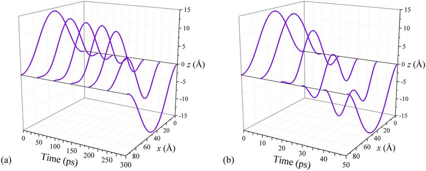
www.nature.com/scientificreports/

                              Figure 1. Schematics of the membrane memcapacitor employing a buckled graphene membrane as its top
                              plate4.

                              elasticity theory focusing on a single-layer graphene membrane with clamped boundary conditions. This choice
                              of boundary conditions is justified by the typically strong adhesion of graphene to substrates. Our results extend
                              our prior DFT investigation14 of the up-to-down snap-through transition of graphene membrane with hinged
                              boundary conditions.
                                  The combination of computational/theoretical methods adds breadth and depth to our analysis. Using MD
                              simulations, we were able to understand main features of the membrane dynamics in the presence of an external
                              force and after the force removal. This understanding has helped us to develop analytical models that resulted
                              in compact algebraic expressions for the threshold switching forces. DFT calculations were used to validate MD
                              results for the up-to-down transition.
                                  This paper is organized as follows. In Sec. “Molecular Dynamics Simulations” we investigate the snap-through
                              transition of graphene membranes using molecular dynamics simulations. In particular, MD simulations of the
                              up-to-down and down-to-up transitions are reported in Subsec. “Up-to-down transition” and “Down-to-up tran-
                              sition”, respectively, while MD simulation details can be found in Supplementary Information (SI) Sec. “MD
                              Simulation Details”. The standard elasticity theory is applied to the membrane switching in Subsec. “Buckling and
                              snapping-through within the theory of elasticity”. A phenomenological analytical model of the snap-through tran-
                              sition is presented in Subsec. “Phenomenological elasticity theory” and in SI Sec. “Phenomenological Elasticity
                              Theory”. Our DFT calculations are summarized in Sec. “Density Functional Theory”. The results obtained within
                              different approaches as well as their implications are discussed in Sec. “Discussion”.
                                  In this paper, the following notations are used:

                                   q - the charge on capacitor (see Eq. (1))
                                   V - the applied voltage (see Eqs (1) and (2))
                                   C - the (memory) capacitance (see Eq. (1))
                                   d - the distance between fixed sides of membrane (see Fig. 1)
                                   h - the distance between the bottom plate and the level of fixed sides (see Fig. 1)
                                   L - the membrane length
                                   w - the membrane width
                                   D = 16 eV - the bending rigidity of graphene
                                   E2D = 340 N/m - the 2D Young’s module
                                   ζ - the deflection of membrane (see Eq. (3))
                                   ζc - the maximum deflection of membrane (see Eq. (7))
                                   θi(s) - the angle that the membrane makes with the horizontal (see Eqs (16) and (17)),
                                   s - the internal coordinate that changes between −1/2 and 1/2 (see Eqs (16) and (17))
                                   Ai and ci - coefficients (see Eqs (16) and (17))
                                   zcm - the center of mass position (see Eq. (19))
                                  Ub, Ustr, Uext - the bending, stretching and external potential contributions to the potential energy of mem-
                                   brane (see Eq. (18))
                                   F↓ - the up-to-down threshold switching force (see Eqs (12), (20), (21) and (22))
                                   F↑ - the down-to-up threshold switching force (see Eqs (14) and (28))
                                   ε0 - the vacuum permittivity

                              Molecular Dynamics Simulations
                              MD simulations are a well established modeling tool frequently employed in studies of nanoscale carbon-based
                              materials15–36. We used classical MD simulations to investigate the dynamics of snap-through transition of buck-
                              led graphene membranes. Zigzag graphene nanoribbons (membranes) of two lengths were considered: the nano-
                              ribbon A, L = 54 Å (22 rings), and nanoribbon B, L = 103 Å (42 rings). Both nanoribbons were of the same width
                              (w = 41 Å). In order to implement the clamped boundary conditions, the first two lines of carbon atoms at shorter
                              sides were kept fixed. The buckling was realized by changing the distance between the fixed sides from L to d < L.
                              The same external force was applied to each atom in the downward direction to simulate the attractive interaction
                              between the plates.
                                  See SI Sec. “MD Simulation Details” for the details of MD simulations.

                              Up-to-down transition. In order to simulate the up-to-down transition, the double-clamped graphene
                              nanoribbon buckled upwards was subjected to the force in the downward direction. The final state of mem-
                              brane was found using MD simulations as described in SI Sec. “MD Simulation Details”. Figure 2 shows the final

ScieNtific RePortS | (2018) 8:3566 | DOI:10.1038/s41598-018-21205-3                                                                           2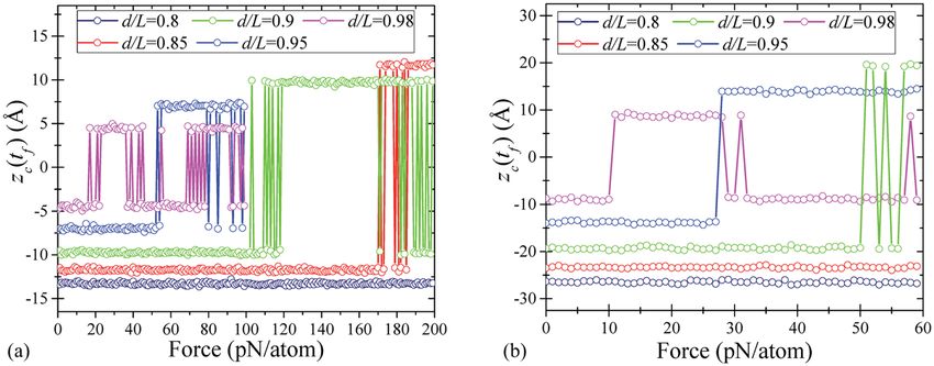
www.nature.com/scientificreports/
Figure 2. Up-to-down transition: the final position (at a time tf) of a central atom of membrane as a function of
the applied force magnitude for (a) shorter membrane A (22 rings length), and (b) longer membrane B (42 rings
length). The calculation details are given in the text.
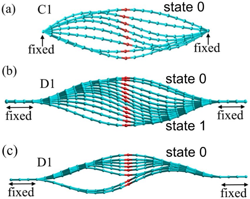
Figure 3. Geometries of membrane B in the process of the up-to-down switching at smaller (F = 0.5 pN/
atom) (a) and larger (F = 1.49 pN/atom) (b) forces. These geometries were obtained using overdamped MD
simulations for d/L = 0.95 (the simulation parameters are provided in the Supplementary Information).
The switching occurs through the non-symmetric path at smaller forces (exceeding the threshold) (a), and
symmetric path at larger forces (b).
position of a central atom of membrane versus the applied force for several values of d/L and two membrane sizes.
According to Fig. 2, at fixed L, the up-to-down threshold switching force (the minimal force required for the
up-to-down transition) is larger for smaller values of d/L. Moreover, at fixed d/L, the threshold switching force
is smaller for longer membranes. Additionally, some curves in Fig. 2 exhibit a noisy threshold (such as d/L = 0.8
and d/L = 0.98 in (a)), which can be related to thermal fluctuations of membranes. All these observations are
intuitively reasonable.
Depending on the force magnitude, the membrane switching occurs either through the symmetric or
non-symmetric membrane profile (see Fig. 3). Figure 3 was obtained using overdamped simulations of mem-
brane dynamics (additional results of these simulations can be found in SI Sec. “MD Simulation Details”). The
non-symmetric profile is associated with a smaller energy barrier14 and involved in switching by smaller forces.
Larger applied forces result in the switching through the symmetric profile. According to our observations and
previous work14, in all cases, the membrane profile is symmetric at short times. If the force magnitude is suffi-
cient to overcome the energy barrier for the symmetric profile, then, typically, the switching takes place through
the symmetric path. Otherwise, a symmetry breaking occurs leading to the switching through the lower energy
barrier associated with the non-symmetric membrane profile. Thermal fluctuations help the symmetry breaking.
Down-to-up transition. It was suggested in ref.4 that the memcapacitor membrane can be set into the buck-
led upwards state 0 (see Fig. 1) by also using the electrostatic attraction between the capacitor plates. When
the pulled-down membrane is suddenly released, there are conditions such that the membrane overcomes the
potential barrier and ends up in the buckled upwards state. As the kinetic energy plays an important role in the
down-to-up transition, this process can not be analyzed using the overdamped dynamics.
ScieNtific RePortS | (2018) 8:3566 | DOI:10.1038/s41598-018-21205-3 3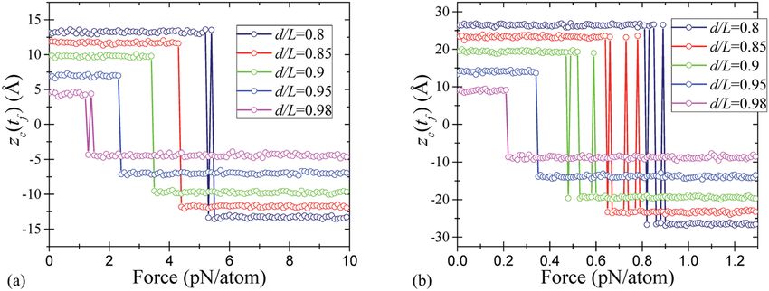
www.nature.com/scientificreports/

                              Figure 4. Down-to-up transition: the final position of a central atom of membrane as a function of the applied
                              force magnitude for (a) shorter membrane A (22 rings length), and (b) longer membrane B (42 rings length).

                                  In order to simulate the down-to-up transition, every atom of a double-clamped buckled membrane was sub-
                              jected to a constant force in -z direction. After an equilibration period, the forces were removed, and the system
                              was simulated for a time interval sufficient to reach the steady state. The final position of a central atom of mem-
                              brane is presented in Fig. 4 as a function of the applied force for several values of d/L.
                                  Figure 4 shows that the threshold forces for the down-to-up transition are larger than those for the up-to-down
                              transition (see Fig. 2). Moreover, the threshold forces for the down-to-up transition are larger for the shorter
                              membrane A compared to the longer membrane B. It is interesting that the final state of membrane oscillates as
                              a function of the applied force (see d/L = 0.98 curves in Fig. 4). Qualitatively, having a high kinetic energy, the
                              membrane moves up and down while its energy dissipates. Finally, it gets trapped in one of two stable buckled
                              states.
                                  Overall, our MD results indicate the possibility of writing one bit of information into the state of membrane
                              memcapacitor. In this interpretation, logic 1 corresponds to the membrane buckled downwards, and logic 0 - to
                              the membrane buckled upwards. In addition to 0 → 1 and 1 → 0 transitions presented in Figs 2 and 4, we have
                              verified the occurrence of 1 → 1 and 0 → 0 transitions at the same values of forces required for 0 → 1 and 1 → 0
                              transitions, respectively. Therefore, logic 0 or 1 can be written into the memcapacitor just by selecting a suitable
                              value of the applied force.
                                  In our work, we considered relatively small nanoribbons, which are mechanically rigid. This is an important
                              requirement for the memcapacitor application as the mechanical nonvolatile information storage is not possible
                              with flexible graphene. From some previous studies37 it is known that local structural corrugations (ripples)38
                              disappear in the transition from flexible to rigid graphene. In agreement with this previous work37, our molecular
                              dynamics simulations have shown the absence of ripples (spontaneous height fluctuations) in nanoribbons of
                              reported sizes and their existence in larger nanoribbons. The latter, however, are not suitable for the memcapac-
                              itor application because of their flexibility. To summarize, while our simulation tools provide a means for ripples
                              detection, we did not observe these in the reported structures that are mechanically rigid.

                              Theory of Elasticity
                              Even though the graphene has a thickness of one atom, the graphene membranes are quantitatively good
                              described by the theory of elasticity39–42. This allows us, on one hand, to obtain analytical expressions for the
                              buckled membranes43–45 and, on the other hand, perform a comparison with MD simulations.
                                  There is a number of publications dealing with buckled beams and membranes under the transverse load (see,
                              for example, refs46–49). Such systems are frequently described in the framework of Euler-Bernoulli theory, which,
                              however, leads to complex analytically unsolvable equations. Bubnov-Galerkin decomposition is a one of the best
                              approaches to find the approximate analytical solution of these equations, although it still requires a complex
                              phase-diagram analysis. In particular, using such analysis, the authors of refs46–49 investigated an electrostatically
                              loaded double-clamped membrane above a rigid flat electrode and derived cumbersome conditions for the sym-
                              metric snap-through transition, symmetry breaking, existence of bifurcation and pull-in instability.
                                  In this Section, we derive compact but sufficiently precise expressions for the snap-through switching forces
                              based on the theory of elasticity.

                              Buckling and snapping-through within the theory of elasticity. Description of buckled membranes
                              within the theory of elasticity. Consider a 2D membrane within the theory of elasticity40,41,50. The total potential
                              energy of membrane is defined by the deflection ζ (along the normal direction z) as
                                                                       D
                                                                 U=
                                                                       2
                                                                           ∬ dS(Δζ )2 + TδS + ∬ dSFζ.                                           (3)
                              Here, Δ stands for the 2D Laplacian, T = T0 + δT is the total tensile force, T0 is the force applied by the support
                              and δT is the bending tension resulted from the extension,

ScieNtific RePortS | (2018) 8:3566 | DOI:10.1038/s41598-018-21205-3                                                                               4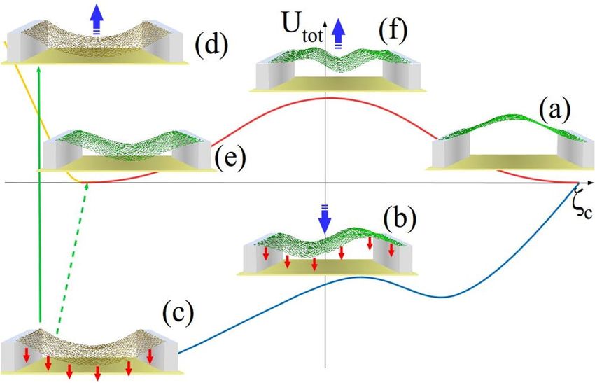
www.nature.com/scientificreports/
δS
δT = E 2 D
S0
, δS = ∬ dS(∇ζ )2 , (4)
S0 = wL, and F is the external force density. The compression of membrane corresponds to T0 < 0.
Given the potential energy, one may also be interested in the dynamics of membrane, which is defined by the
equation
∂ 2ζ ∂ζ
µ + µγ − F = − D∆∆ζ + T∆ζ ,
∂t 2 ∂t (5)
where μ is the 2D mass density.
Eigenmodes and buckling. The spatial harmonics (eigenmodes) of clamped membranes can be written as
x x cosh bn − cos bn
ζ n(x ) = coshbn − cosbn − sinhbn x − sinbn x ,
d d sinh bn − sin bn
d
d (6)
where the numbers bn are the solutions of the equation cosh bncos bn = 1. One can find that bn ≈ 3π/2 + nπ (in
particular, b0 = 4.73 is close to 3π/2 = 4.65). The functions ζn(x) are orthonormal.
Consider a buckled membrane shown in Fig. 1. Its potential energy (Eq. (3)) calculated for the fundamental
n = 0 mode (taking ζ(x) = ζ0(x) with ζ(d/2) ≡ ζc) is
U =− αζc2 + βζc4 + fζc , (7)
where α = π w(|T0| − Tc)/(4d), β = 3π Dw/(4ε d ), and f = πFdw/6. Here, Tc = 4π D/d is the critical tension. At
2 4 2 3 2 2
α > 0, that is at |T0| > Tc, the potential is the double-well potential with minima at symmetric deflections,
ζc = ± α/2β , and the potential barrier δU = α2/4β. (We note that a less realistic case of hinged boundary condi-
tions would lead to simpler expressions for eigenmodes, ∼ sin(πnx /d ), compared to Eq. (6), making the hinged
boundary conditions preferable for some calculations. However, this case results in quantitatively different values.
For example, the critical tension differs four times.)
We note that the nanoribbon length is given by
d
L= ∫0 dx 1 + ζ ′2 .
(8)
Expanding this expression to the second order, one obtains the interrelation between L, d, and the maximal
deflection ζc:
d
ζc ≈ 0.64 8 L(L − d ) .
L (9)
On the other hand, the maximal deflection of buckled membrane can be inferred from the minima of the poten-
tial energy, Eq. (7):
α 2 L2
ζc2 = = 2 ( T0 − Tc) .
2β π E 2D (10)
Equations (9) and (10) link the tensile force T0 to the parameter d/L, which can be considered as a measure of
deformation of buckled membrane. These equations can be used to express the tensile force T0 through d/L.
Snap-through transition. Here we present a convenient method to describe the dynamics of membrane sub-
jected to an external force and find the minimal force causing its snap-through transition. The main idea is to
expand ζ(x, t) in harmonics ζn(x) (given by Eq. (6)) with amplitudes qn(t) as
ζ (x , t ) = ∑qn (t )ζ n(x ),
n (11)
and limit the sum to few first terms. We found that in order to describe the symmetric and non-symmetric tran-
sitions, it is sufficient to consider n = 0,2 and n = 0,1 terms in Eq. (11), respectively. The calculation consists in the
following. First, we substitute the expansion (11) in Eq. (5). Second, the resulting equation is multiplied by ζm(x)
and integrated taking into account the orthogonality of harmonics. Here we emphasize that for the harmonics (6),
the integrals are readily calculated, and instead of the integro-differential equation one obtains a system of differ-
ential equations for the functions qn(t). Inserting the obtained functions qn(t) back into Eq. (11) gives us the
description of membrane dynamics. In the following, the results of these calculations (performed using the time
normalized by the membrane characteristic frequency ωc = (1/L2) D /μ and tc = 1/ωc)51 are analyzed for mem-
brane B.
Consider the results presented in Fig. 5. Figure 5(a) demonstrates the case of fully symmetric switching, when
the dynamics can be described by n = 0 and 2 harmonics. Next, we introduce a small asymmetry into the problem
via a small non-symmetric modification of the force (of the order of 0.1%). This results in the non-symmetric
dynamics of Fig. 5(b), which can be described in terms of n = 0 and 1 harmonics. We note that the force needed
ScieNtific RePortS | (2018) 8:3566 | DOI:10.1038/s41598-018-21205-3 5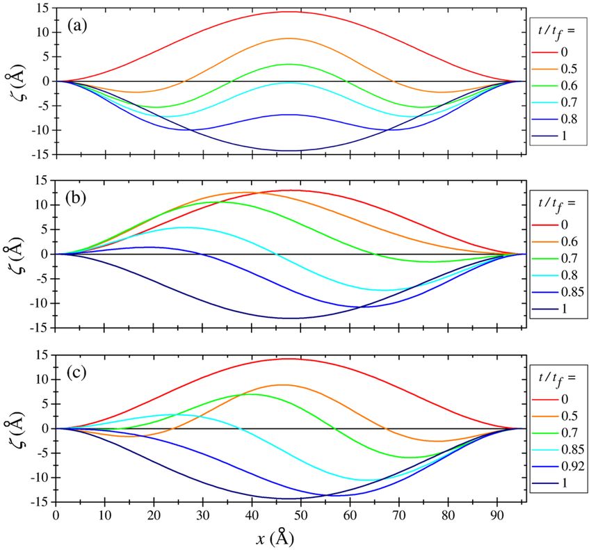
www.nature.com/scientificreports/

                              Figure 5. Up-to-down transition within the theory of elasticity. (a) Fully symmetric switching. (b) Non-
                              symmetric switching caused by a small asymmetry in the applied force. (c) More realistic switching scenario
                              based on a symmetric force, where the initial symmetric distortion becomes non-symmetric at longer times. For
                              all panels d/L = 0.95.

                              Figure 6. Numerical simulation of up-to-down transition. (a) The final central-point deflection ζc versus the
                              applied transverse force F for several values of d/L. (b) Time-dependence of the first few harmonics’ amplitudes
                              qn(t).

                              for the non-symmetric snap-through transition is smaller than that for the symmetric one, which will also be
                              analyzed below in more detail. Finally, in Fig. 5(c) we illustrate a combination of the above regimes found using
                              a symmetric force, when a tiny fluctuation in the numerical solution changes the symmetric dynamics to the
                              non-symmetric one. Note that this case is close to the one discussed in ref.14.
                                  Figure 6(a) depicts the dependence of the final position of membrane center, ζc(tf), on the applied force F. At a
                              certain value of force, F = F↓, the membrane switches from the buckled upwards state to the buckled downwards
                              state. Our calculations show that the threshold force is proportional to the initial central-point deflection ζc and
                              is different for the symmetric (s) and non-symmetric (ns) dynamics. Namely, this force, being multiplied by the
                              membrane area wL, reads

ScieNtific RePortS | (2018) 8:3566 | DOI:10.1038/s41598-018-21205-3                                                                              6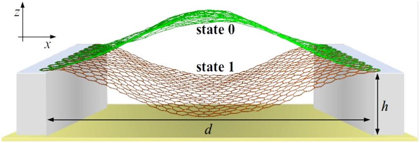
www.nature.com/scientificreports/
3/8
Fs↓,ns ζc L L
= Cs ,ns 2.44 = Cs ,ns − 1,
F0 d d d (12)
Dw
F0 = , Cns = 253.4, Cs = 359.1.
L2 (13)
Since the non-symmetric transition is energetically favorable, we expect that this value of force is the one to
be used in the device design/experiment analysis. We note that estimations based on Eq. (12) are in a good agree-
ment with results found by other methods as we discuss later and illustrate in Sec. “Discussion” below. Figure 6(b)
presents the time-dependence of harmonics’ amplitudes qn(t) in the up-to-down transition. Importantly, the
dynamics is well described by n = 0, 1, and 2 harmonics, while n = 3 and 4 harmonics amplitudes are negligibly
small.
Our calculations (similar to the consideration of the up-to-down force above) demonstrate that the minimal
force needed for the down-to-up transition is proportional to ζc2 as
2 3/4
F↑ ζ L L
= C ↑2.44 c = C ↑ − 1,
F0
d
d
d (14)
C ↑ = 8.48 ⋅ 104 . (15)
See also SI Subsec. “Down-to-up transition”, where the down-to-up transition is illustrated graphically.
Phenomenological elasticity theory. In this Section, in order to avoid all complications associated
with the Bubnov-Galerkin decomposition, we elaborate a different approach describing the up-to-down and
down-to-up transitions in a compact analytical form.
Ansatz. Following our observation of the existence of the symmetric and non-symmetric membrane profiles in
the snap-through transition (see Fig. 3), we introduce two simplest polynomial functions to describe such sym-
metric (s) and non-symmetric (ns) shapes of membrane:
1
θs(s) = As s 2 − s(s 2 − c 02),
4 (16)
1
θns (s) = Ans s 2 − (s − c1)(s − c 2).
4 (17)
Here θi(s) is the angle that the membrane makes with the horizontal, s is the internal coordinate that changes
between −1/2 and 1/2, Ai and ci are coefficients, and i = {s, ns}. Clearly, Eqs (16) and (17) describe the
double-clamped membrane as θi(±1/2) = 0.
Up-to-down transition. Our goal here is to estimate the minimal force required for the snap-through transition.
In this subsection, we assume that the snap-through transition is induced by a slowly increasing force such that
the system always stays in the potential energy minimum. At zero applied force, there are two minima of the
potential energy corresponding to the two stable states of membrane. The applied force modifies the potential
energy landscape such that, starting at a certain force, the potential energy has a single minimum. Here, this value
of force is found and considered as an estimation for the threshold switching force.
In the presence of a constant force F in the downward direction, the membrane potential energy is given by
2
Dw 1/2 ∂θ
U = Ub + Ustr + Uext =
2L ∫−1/2 ∂s ds + Ustr + Uext, (18)
where Ub is the bending energy, Ustr is the stretching energy, Uext is the potential energy due to the applied force.
Then, using Uext = Fzcm, where zcm is z coordinate of the center of mass, and neglecting Ustr term not important for
the up-to-down transition (see, e.g., Fig. S1 that indicates the insignificance of Ustr in buckled membrane), we get
the following equation for the potential energy extrema:
−1
dUb dU dz
F=− = − b cm ,
dzcm dci dci (19)
where i = {0, 1} corresponds to {s, ns}, respectively. Equation (19) allows finding c0 and c1 for a given strength of
the applied force.
The minimal force needed for the snap-through transition corresponds to the maximum of F(zcm) and, for the
transition through the symmetric shape, is given by
ScieNtific RePortS | (2018) 8:3566 | DOI:10.1038/s41598-018-21205-3 7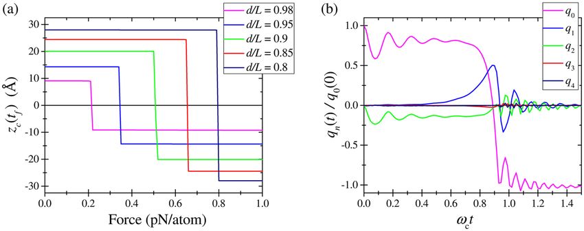
www.nature.com/scientificreports/
Dw L−d
Fs↓ = 440
L2 L (20)
taking place at c0 = 0.3589 (the corresponding membrane profile is presented in Fig. S4). At this value of c0, the
bending energy is Ub,s = 108Dw(L − d)/L2. Performing the same calculations for the non-symmetric shape, one
can find that the force needed to support the equilibrium non-symmetric shape decreases with the progress of
switching. A zero force is reached at c1 = − c 2 = 1/(2 5 ) that corresponds to the maximum of
Ub,ns = 90Dw(L − d)/L2. A possible (rough) estimation for the threshold switching force can be obtained taking
the limit c1 → ∞ leading to
↓ Dw L−d
Fns = 281
L2 L (21)
and Ub,ns = 42Dw(L − d)/L .2
In fact, a realistic scenario of the switching through the non-symmetric shape can be imaged as follows. We
start with a symmetric membrane at F = 0 and slowly increase the force. The symmetry breaking occurs at a
certain value of force, say, F↓. The dynamics of switching is a complex process significantly relying on thermal
fluctuations. As the switching dynamics can not be reached within the framework of our model, for estimation
purposes, we assume that F↓ corresponds to the point where the bending energies and applied forces for the sym-
metric and non-symmetric shapes are the same. One can find that both conditions are satisfied at c0 = 0.4683 and
c1 = 0.6948, so that Ub = 47.8Dw(L − d)/L2 and
Dw L−d
F ↓ = 263.53 .
L2 L (22)
Consequently, at F < F , the membrane keeps the symmetric shape and switches to the non-symmetric one as
↓
soon as F reaches F↓. As there is no barrier involved in the non-symmetric switching, no further increase in the
applied force is required to complete the snap-through transition through the non-symmetric shape.
Down-to-up transition. As the stretching energy Ustr (see Eq. (18)) plays an important role in the down-to-up
transition, it needs to be taken into account. For our purposes, it is sufficient to approximate Ustr as
E 2Dw 2
Ustr = ΔL ,
2L (23)
where ΔL is the change in the membrane length. In the approximation of small elongation, ΔL L, one can
assume that both Ub and the shape of the stretched membrane are not significantly modified compared to F = 0
case. In this situation, at the threshold of transition, the stretching energy (Eq. (23)) is equal to the difference
between the maximal and minimal bending energies (the energy conservation condition). Using the energies
given below Eq. (S8) we find
E 2Dw 2 L−d
ΔL = Ubmax − Ubmin = 161Dw 2 .
2L L (24)
Moreover, at equilibrium
E 2Dw d(ΔL2)
F(zcm) = ⋅ .
2L dzcm (25)
Under the condition of small ΔL L, the center of mass position of membrane (buckled downwards) can be
expressed as
dzcm
zcm⁎ = − 0.3187 L(L − d ) + ΔL ,
d(ΔL) (26)
with
dzcm 2L − d
= 0.3187 .
d(ΔL) 2 L(L − d ) (27)
Using Eqs (24) and (27), Eq. (25) can be rewritten as
w L−d
F ↑ = 79.62 2DE 2D .
L 2L − d (28)
We have verified that the threshold switching force for the down-to-up transition given by Eq. (28) is in agree-
ment with our typical MD simulations results. A very good agreement was obtained with MD simulations per-
formed with very small energy dissipations.
ScieNtific RePortS | (2018) 8:3566 | DOI:10.1038/s41598-018-21205-3 8www.nature.com/scientificreports/
Figure 7. Geometries of membranes C1 (hinged boundary conditions, (a)) and D1 (clamped boundary, (b,c))
in the process of the up-to-down switching. The switching occurs through non-symmetric paths (a,b), and
initially symmetric path (c). These geometries were found using DFT optimization of geometries obtained
utilizing a progressive displacement of central atoms.
Density Functional Theory
A DFT investigation of the up-to-down transition was performed following the previously reported study of the
up-to-down switching of buckled graphene membrane14. In the present calculations, we focused on the effects of
boundary conditions and buckling strength on the up-to-down threshold switching force. DFT computational
details can be found in SI Sec. “DFT Calculations”.
We investigated a buckled zigzag graphene nanoribbon specified in SI. Two types of boundary conditions
were examined: (1) hinged boundary conditions (configurations C1 with d/L = 0.96, Fig. 7(a), C2 with d/L = 0.78,
and C3 with d/L = 0.63), and (2) clamped boundary conditions (configuration D1 with d/L = 0.96, Fig. 7(b,c)).
The initial geometries of nanoribbons corresponded to the buckled upwards state. In order to simulate the
up-to-down transition, we used the approach developed in ref.14. Specifically, we performed a series of DFT cal-
culations with the central chain of membrane atoms (marked red in Fig. 7) gradually displaced in −z direction
from its position in the buckled upwards state. The membrane geometry found at the preceding deformation step
was used to build its subsequent modification. In contrast to ref.14, in the present calculations only z coordinates
of the central chain of atoms were constrained.
The deformation energies of buckled graphene are reported in SI. Our force estimation shows that the thresh-
old switching force for the up-to-down transition is about 3.8 pN/atom for C1, 11.1 pN/atom for C2, and 16.4 pN/
atom for C3. Moreover, the non-symmetric switching force for D1 is 3.7 pN/atom and the symmetric one is about
11.5 pN/atom. As the non-symmetric switching forces for D1 and C1 are close to each other, we use the results for
C1-C3 for the order-of-magnitude comparison with MD and elasticity theory results.
Discussion
Four methods to describe the snap-through transitions. As the key finding, Fig. 8 presents the
dependence of the up-to-down threshold switching force (calculated with different approaches) on the membrane
deformation parameter d/L. In particular, this figure demonstrates that the threshold forces obtained by a number
of different methods are in good agreement with each other.
We emphasize that:
(i) MD is widely used approach to describe the dynamics of nanoscale systems. In our work, MD clearly shows the
possibility of 0 → 1 and 1 → 0 transitions of graphene membrane. We have also verified the occurrence of 1 → 1
and 0 → 0 transitions at the same values of forces required for 0 → 1 and 1 → 0 transitions, respectively.
(ii) In the framework of elasticity theory, the membrane is described by means of an integro-differential
equation for the deflection ζ(x, t). Expanding the function ζ(x, t) into membrane’s harmonics allows
reducing the integro-differential equation to a system of differential equations. This approach was utilized
in Subsec. “Buckling and snapping-through within the theory of elasticity”. There it was shown that the
up-to-down threshold switching force depends linearly on the initial central-point deflection, F↓ ∝ ζc, while
the down-to-up snap-through force at low dissipation depends quadratically on the initial deflection,
F ↑ ∝ ζc2. Besides, we have demonstrated that with a high accuracy, the relevant membrane’s dynamics can
be described (and visualized) just by two harmonics.
(iii) The phenomenological approach based on the theory of elasticity has allowed us to obtain analytical
expressions for the up-to-down and down-to-up switching forces for buckled graphene membrane. The
forces for 0 → 1 and 1 → 0 transitions are in a good agreement with MD simulations results.
ScieNtific RePortS | (2018) 8:3566 | DOI:10.1038/s41598-018-21205-3 9www.nature.com/scientificreports/
Figure 8. Comparison between the up-to-down threshold forces, calculated by four different approaches.
Green, red, and blue lines were calculated in the non-symmetric, adiabatic and dynamic symmetric switching
regimes, respectively. The results of our MD simulations are shown with squares for nanoribbon A and circles
for B. The forces calculated by means of the elasticity theory, Eq. (12), are shown with the magenta solid line for
the non-symmetric snap-through and with the orange dashed line for the symmetric transition. The DFT results
are presented by triangles.
(iv) DFT is a non-standard method for studying mechanical properties of membranes. Similarly to other meth-
ods, DFT has shown that the non-symmetric switching pathway is the preferable one. This method also
provides a consistent estimation for the up-to-down threshold switching force.
Implications for memcapacitor design. From the application point of view, the membrane memca-
pacitor should have a strong ‘memory content’, namely, the device characteristics in its two logic states should
be sufficiently different so as to provide a significant influence on other elements of electronic circuits52. For
this purpose, it is desirable that both the distance between the fixed edge of membrane and second electrode
(h in Fig. 1) and the maximal deflection of membrane (zs(0)) are chosen (much) smaller than the membrane
length. Moreover, the gap between electrodes should be larger than the maximal membrane deflection,
h > zs(0) (see Eq. (S2) for the definition of zi(s)). For given capacitances C0 and C1 of the states 0 and 1 (logic 1
corresponds to the membrane buckled downwards, and logic 0 - to the membrane buckled upwards) such that
C1/C0 < 3.01, one can find that
C1 + C0
h = 0.3210 L(L − d ) .
C1 − C0 (29)
Next, we need an expression for the force applied to the membrane expressed through the input variable of
memcapacitor such as the applied voltage V (see Eqs (1) and (2)). Since the energy of the plate can be written as
ε0V 2A
Uext(zcm) = − ,
2(h + zcm) (30)
where ε0 is the vacuum permittivity and A = d · w is the plate area, the force is given by
ε0V 2A
F(zcm) = − .
2(h + zcm)2 (31)
The overall scheme of memcapacitor switching is schematically presented in Fig. 9. Let us consider first the
up-to-down transition (path (a–c,f) in Fig. 9). As mentioned in SI Sec. “Phenomenological Elasticity Theory”, the
smallest threshold force for this transition is associated with the switching through the non-symmetric г state and
corresponds to c1⁎ = 0.6948. In this way, the buckled upwards membrane (structure (a) in Fig. 9) evolves into the
buckled downwards state according to (b) and (c) in Fig. 9. After the voltage removal, the membrane remains in
the buckled downwards state ((e) in Fig. 9). In order to estimate the minimal (threshold) voltage required for this
transition, Eq. (22) is rewritten accounting for Eq. (31):
ε0V 2dw Dw L−d
= 263.53 2 .
2(h + zcm(c1⁎))2 L L (32)
ScieNtific RePortS | (2018) 8:3566 | DOI:10.1038/s41598-018-21205-3 10www.nature.com/scientificreports/
Figure 9. Schematic representation of transition pathways in the switching of membrane memcapacitor (red
arrows represent the applied electrostatic force, bold blue arrows represent the movement of membrane).
The buckled upwards membrane (structure (a)) evolves into the buckled downwards state (c) through a non-
symmetric transition state (b). Note that in the presence of force, (c) is also a transition state. After a slow voltage
removal (dashed green arrow), the membrane remains in the buckled downwards state (e) (the up-to-down
transition). In case of fast force removal, the membrane does not have enough time to relax its tension
(d) and start moving into the upward state (a) through a symmetric transition state (f) (the down-to-up transition).
Consequently,
h + zcm(c1⁎) D L−d
V0 → 1 = 22.96 ,
L ε0 ⋅ d L (33)
where zcm(c1⁎) = 0.3203 L(L − d ) . Eq. (33) provides an easy way to find the threshold voltage necessary for the
up-to-down transition of membrane.
In the down-to-up transition, the initial buckled downwards membrane ((e) in Fig. 9) is first stretched by the
applied force ((c) in Fig. 9). When the force is removed, the membrane state becomes (d). If the potential energy
of (d) is sufficient to overcome the potential barrier height symmetrically (f), then the membrane may end up in
the buckled upwards state (a). These general processes are partially described by Eqs (24) and (25). Because of the
membrane elongation in (c,d), a refined value of zcm should be used in relevant calculations.
The threshold voltage can be estimated based on the energy conservation (Eq. (24)) and force equilibrium (Eq.
⁎
(25)) conditions accounting for zcm from Eqs (26) and (27). One can find that
ε0V 2d ⋅ w w (L − d )
⁎ 2
= 79.62 2DE 2D
2(h + zcm ) L (2L − d ) (34)
and
⁎ 2DE 2D (L − d )
V1 → 0 = 12.62(h + zcm ) .
ε0 ⋅ d ⋅ L (2L − d ) (35)
An additional aspect of membrane dynamics – an estimation of thermally-induced switching time – is considered
in SI Sec. “Stability of Buckled Membrane”.
Concluding Remarks
We have investigated the snap-through transition of a buckled graphene membrane using a variety of computa-
tional and theoretical tools. The main results of this paper are the expressions for the threshold switching forces
(Eqs (12 and 22) for the up-to-down transition and Eqs (14 and 28) for the down-to-up one) and corresponding
voltages (Eqs (33) and (35)). Our analytical results are supported by the results of numerical simulations, MD
and DFT calculations. We expect that our findings will find applications in the design, fabrication and analysis of
membrane-based memory devices.
References
1. Di Ventra, M., Pershin, Y. V. & Chua, L. O. Circuit elements with memory: Memristors, memcapacitors, and meminductors. Proc.
IEEE 97, 1717–1724 (2009).
2. Traversa, F. L., Bonani, F., Pershin, Y. V. & Di Ventra, M. Dynamic computing random access memory. Nanotechnology 25, 285201
(2014).
3. Pershin, Y. V., Traversa, F. L. & Di Ventra, M. Memcomputing with membrane memcapacitive systems. Nanotechnology 26, 225201
(2015).
ScieNtific RePortS | (2018) 8:3566 | DOI:10.1038/s41598-018-21205-3 11www.nature.com/scientificreports/
4. Martinez-Rincon, J. & Pershin, Y. V. Bistable non-volatile elastic membrane memcapacitor exhibiting chaotic behavior. IEEE Trans.
El. Dev. 58, 1809 (2011).
5. Lai, Q. et al. Analog memory capacitor based on field-configurable ion-doped polymers. Appl. Phys. Lett. 95, 213503 (2009).
6. Martinez-Rincon, J., Di Ventra, M. & Pershin, Y. V. Solid-state memcapacitive system with negative and diverging capacitance. Phys.
Rev. B 81, 195430 (2010).
7. Shevchenko, S. N., Pershin, Y. V. & Nori, F. Qubit-based memcapacitors and meminductors. Phys. Rev. Applied 6, 014006 (2016).
8. Pershin, Y. V. & Di Ventra, M. Memory effects in complex materials and nanoscale systems. Advances in Physics 60, 145–227 (2011).
9. Lindahl, N. et al. Determination of the bending rigidity of graphene via electrostatic actuation of buckled membranes. Nano Lett. 12,
3526–3531 (2012).
10. Weber, P., Guttinger, J., Tsioutsios, I., Chang, D. E. & Bachtold, A. Coupling graphene mechanical resonators to superconducting
microwave cavities. Nano Lett. 14, 2854–2860 (2014).
11. Lambin, P. Elastic properties and stability of physisorbed graphene. Appl. Sci. 4, 282 (2014).
12. Benameur, M. M. et al. Electromechanical oscillations in bilayer graphen. Nat. Comm. 6, 8582 (2015).
13. Davidovikj, D. et al. Visualizing the motion of graphene nanodrums. Nano Lett. 16, 2768–2773 (2016).
14. Sedelnikova, O. V., Bulusheva, L. G., Okotrub, A. V. & Pershin, Y. V. Spontaneous symmetry breaking during the switching of a
buckled graphene membrane. JETP Letters 103, 244–247 (2016).
15. Yakobson, B. I., Brabec, C. J. & Bernholc, J. Nanomechanics of carbon tubes: Instabilities beyond linear response. Phys. Rev. Lett. 76,
2511–2514 (1996).
16. Berber, S., Kwon, Y.-K. & Tománek, D. Unusually high thermal conductivity of carbon nanotubes. Phys. Rev. Lett. 84, 4613–4616
(2000).
17. Yao, Z., Zhu, C.-C., Cheng, M. & Liu, J. Mechanical properties of carbon nanotube by molecular dynamics simulation. Comp. Mat.
Sc. 22, 180–184 (2001).
18. Legoas, S. B. et al. Molecular-dynamics simulations of carbon nanotubes as gigahertz oscillators. Phys. Rev. Lett. 90, 055504 (2003).
19. Maruyama, S. A molecular dynamics simulation of heat conduction of a finite length single-walled carbon nanotube. Micr.
Thermophys. Eng. 7, 41–50 (2003).
20. Lee, G.-D., Wang, C. Z., Yoon, E., Hwang, N.-M. & Ho, K. M. Vacancy defects and the formation of local haeckelite structures in
graphene from tight-binding molecular dynamics. Phys. Rev. B 74, 245411 (2006).
21. Shiomi, J. & Maruyama, S. Non-fourier heat conduction in a single-walled carbon nanotube: Classical molecular dynamics
simulations. Phys. Rev. B 73, 205420 (2006).
22. Wang, C. Y., Mylvaganam, K. & Zhang, L. C. Wrinkling of monolayer graphene: A study by molecular dynamics and continuum
plate theory. Phys. Rev. B 80, 155445 (2009).
23. Hu, J., Ruan, X. & Chen, Y. P. Thermal conductivity and thermal rectification in graphene nanoribbons: A molecular dynamics study.
Nano Letters 9, 2730–2735 (2009).
24. Jiang, J.-W., Wang, J.-S. & Li, B. Young’s modulus of graphene: A molecular dynamics study. Phys. Rev. B 80, 113405 (2009).
25. Martins, B. & Galvao, D. Curved graphene nanoribbons: structure and dynamics of carbon nanobelts. Nanotechnology 21, 075710
(2010).
26. Neek-Amal, M. & Peeters, F. M. Graphene nanoribbons subjected to axial stress. Phys. Rev. B 82, 085432 (2010).
27. Ni, Z. et al. Anisotropic mechanical properties of graphene sheets from molecular dynamics. Phys. B: Cond. Matt. 405, 1301–1306
(2010).
28. Lebedeva, I. V., Knizhnik, A. A., Popov, A. M., Lozovik, Y. E. & Potapkin, B. V. Interlayer interaction and relative vibrations of bilayer
graphene. Phys. Chem. Chem. Phys. 13, 5687–5695 (2011).
29. Bagri, A., Kim, S.-P., Ruoff, R. S. & Shenoy, V. B. Thermal transport across twin grain boundaries in polycrystalline graphene from
nonequilibrium molecular dynamics simulations. Nano Lett. 11, 3917–3921 (2011).
30. Min, K. & Aluru, N. R. Mechanical properties of graphene under shear deformation. Appl. Phys. Lett. 98, 013113 (2011).
31. Ng, T., Yeo, J. & Liu, Z. A molecular dynamics study of the thermal conductivity of graphene nanoribbons containing dispersed
stone–thrower–wales defects. Carbon 50, 4887–4893 (2012).
32. Rajabpour, A. & Allaei, S. M. V. Tuning thermal conductivity of bilayer graphene by inter-layer sp3 bonding: A molecular dynamics
study. Appl. Phys. Lett. 101, 053115 (2012).
33. Kalosakas, G., Lathiotakis, N. N., Galiotis, C. & Papagelis, K. In-plane force fields and elastic properties of graphene. J. Appl. Phys.
113, 134307 (2013).
34. Berdiyorov, G., Neek-Amal, M., Peeters, F. & van Duin, A. C. Stabilized silicene within bilayer graphene: A proposal based on
molecular dynamics and density-functional tight-binding calculations. Phys. Rev. B 89, 024107 (2014).
35. Kang, J. W. & Hwang, Z. Position-dependent mechanical responses of nanoindented graphene nanoribbons: Molecular dynamics
study. J. Korean Phys. Soc. 67, 625–633 (2015).
36. Yamaletdinov, R. D. & Pershin, Y. V. Finding stable graphene conformations from pull and release experiments with molecular
dynamics. Scientific Reports 7, 42356 (2017).
37. Schoelz, J. K. et al. Graphene ripples as a realization of a two-dimensional Ising model: A scanning tunneling microscope study. Phys.
Rev. B 91, 045413 (2015).
38. Fasolino, A., Los, J. H. & Katsnelson, M. I. Intrinsic ripples in graphene. Nature Materials 6, 858 (2007).
39. Eriksson, A. M., Midtvedt, D., Croy, A. & Isacsson, A. Frequency tuning, nonlinearities and mode coupling in circular mechanical
graphene resonators. Nanotechnology 24, 395702 (2013).
40. Tomi, M. et al. Buckled diamond-like carbon nanomechanical resonators. Nanoscale 7, 14747 (2015).
41. Abdi, M., Degenfeld-Schonburg, P., Sameti, M., Navarrete-Benlloch, C. & Hartmann, M. J. Dissipative optomechanical preparation
of macroscopic quantum superposition states. Phys. Rev. Lett. 116, 233604 (2016).
42. Bonilla, L. L. & Ruiz-Garcia, M. Critical radius and temperature for buckling in graphene. Phys. Rev. B 93, 115407 (2016).
43. Qiu, J., Lang, J. H. & Slocum, A. H. A curved-beam bistable mechanism. J. Microelectromech. Sys. 13, 137 (2004).
44. Cazottes, P., Fernandes, A., Pouget, J. & Hafez, M. Bistable buckled beam: Modeling of actuating force and experimental validations.
J. Mech. Des. 131, 101001 (2009).
45. Bitarafan, M. H. et al. Thermo-mechanical characterization of on-chip buckled dome fabry-perot microcavities. J. Opt. Soc. Am. B
32, 1214 (2015).
46. Medina, L., Gilat, R. & Krylov, S. Symmetry breaking in an initially curved pre-stressed micro beam loaded by a distributed
electrostatic force. Int. J. Solid. Struct. 51, 2047–2061 (2014).
47. Chen, X. & Meguid, S. A. On the parameters which govern the symmetric snap-through buckling behavior of an initially curved
microbeam. Int. J. Solid. Struct. 66, 77–87 (2015).
48. Krylov, S., Ilic, B. R., Schreiber, D., Seretensky, S. & Craighead, H. The pull-in behavior of electrostatically actuated bistable
microstructures. J. Micromech. Microeng. 18, 055026 (2008).
49. Medina, L., Gilat, R. & Krylov, S. Symmetry breaking in an initially curved micro beam loaded by a distributed electrostatic force.
Int. J. Solid. Struct. 49, 1864–1876 (2012).
50. Landau, L. D. & Lifshitz, E. M. Theory of Elasticity (Pergamon Press 1975).
51. Gomez, M., Moulton, D. E. & Vella, D. Critical slowing down in purely elastic ‘snap-through’ instabilities. Nat. Phys 13, 142 (2017).
52. Di Ventra, M. & Pershin, Y. V. The parallel approach. Nature Physics 9, 200 (2013).
ScieNtific RePortS | (2018) 8:3566 | DOI:10.1038/s41598-018-21205-3 12www.nature.com/scientificreports/
Acknowledgements
This work has been supported by the Russian Science Foundation grant No. 15-13-20021. OVI and SNS
acknowledge a partial support by the State Fund for Fundamental Research of Ukraine (grant No. F66/95-2016).
Author Contributions
R.D.Y. and Y.V.P. did the MD calculations and developed the Phenomenological elasticity theory. O.V.I. and S.N.S.
developed the Buckling and snapping-through within the theory of elasticity. O.V.S. did the DFT calculations. All
authors discussed the results and co-wrote the manuscript.
Additional Information
Supplementary information accompanies this paper at https://doi.org/10.1038/s41598-018-21205-3.
Competing Interests: The authors declare no competing interests.
Publisher's note: Springer Nature remains neutral with regard to jurisdictional claims in published maps and
institutional affiliations.
Open Access This article is licensed under a Creative Commons Attribution 4.0 International
License, which permits use, sharing, adaptation, distribution and reproduction in any medium or
format, as long as you give appropriate credit to the original author(s) and the source, provide a link to the Cre-
ative Commons license, and indicate if changes were made. The images or other third party material in this
article are included in the article’s Creative Commons license, unless indicated otherwise in a credit line to the
material. If material is not included in the article’s Creative Commons license and your intended use is not per-
mitted by statutory regulation or exceeds the permitted use, you will need to obtain permission directly from the
copyright holder. To view a copy of this license, visit http://creativecommons.org/licenses/by/4.0/.
© The Author(s) 2018
ScieNtific RePortS | (2018) 8:3566 | DOI:10.1038/s41598-018-21205-3 13You can also read