An Improved Wrist Kinematic Model for Human-Robot Interaction
←
→
Page content transcription
If your browser does not render page correctly, please read the page content below
An Improved Wrist Kinematic Model for Human-Robot Interaction
                                                                                                 Ningbo Yu1 and Chang Xu2

                                            Abstract— Human kinematics is of fundamental importance                   parametric kinematics inevitably occur due to the assumption
                                         for rehabilitation and assistive robotic systems that physically             that there is only rotational motion in wrist joints and the
                                         interact with human. The wrist plays an essential role for                   upper limb is decoupled into independent segments [7]. So-
                                         dexterous human-robot interaction, but its conventional kine-
                                         matic model is oversimplified with intrinsic inaccuracies and its            phisticated coupled mechanism and dexterous movements of
                                         biomechanical model is too complicated for robotic applications.             the upper extremity can not be fully investigated and explained
                                                                                                                      through the oversimplified conventional kinematic model.
arXiv:2002.05790v1 [cs.RO] 13 Feb 2020

                                         In this work, we establish an improved kinematic model of the
                                         wrist. In vivo kinematic behavior of the wrist was investigated              Therefore, functional assessments on wrist and mechanical
                                         through noninvasive marker-less optical tracking. Data analysis              implementation of rehabilitation devices would have deficits
                                         demonstrated the existence of measurable dynamic axes in
                                         carpal rotation, justifying inevitable misalignment between the              in kinematic analysis and biomechanical evaluation.
                                         wrist and robotic representation if using the conventional wrist                Different from conventional kinematic models, some
                                         model. A novel wrist kinematic model was then proposed with                  studies have investigated the coupled limb biomechanics
                                         rigid body transformation in fusion with a varying prismatic                 quantitatively. The coupled arm impedance measured by dy-
                                         term indicating the dynamic axes location. Accurate and real-                namic characteristics like inertia, damping and stiffness were
                                         time estimation of this term has been achieved through coupled
                                         wrist angles with nonlinear regression. The proposed model                   presented and estimated under muscular co-contraction [11].
                                         is not only accurate but also conveniently applicable for                    Flexible movements in distal arm are essential for dexterous
                                         translating anatomical behaviors into robotic implementation                 manipulation and passive stiffness of those coupled joints
                                         and functional assessment for precise and dexterous human-                   were also estimated quantitatively [12].
                                         robot interaction.                                                              Besides robotic rehabilitation studies, biomechanical inves-
                                                               I. INTRODUCTION                                        tigations of wrist and forearm provide detailed descriptive
                                            Neurorehabilitation therapies promote partial or complete                 data and rational estimation of joint kinematics. An improved
                                         restore upper extremity functions after injury to the central                elasto-kinematic model of the forearm was proposed and it
                                         or peripheral nervous system [1], [2]. Compared with con-                    justified the relative motion (displacements between forearm
                                         ventional constrained-induced therapeutic approaches, robot-                 bones) in proximal radio-ulnar joint instead of describing
                                         assisted therapies have demonstrated potential advantages on                 radio-ulnar joints as universal joints [13]. Both in vitro and in
                                         adaptive engagement, quantitative evaluation of rehabilitation               vivo studies on carpal bone kinematics during wrist motion
                                         process, and clinical assessment [3], [4], [5]. Moreover,                    demonstrated that there is no fixed instantaneous screw axes
                                         for physical human-robot interaction in rehabilitation and                   of wrist rotation and sophisticated carpal joints can not be
                                         assistive applications, human kinematics is of fundamental                   simplified as universal joints due to the evident translation
                                         importance.                                                                  between carpal bones [14], [15]. To assess kinematics and
                                            Motion tracking and kinematic analysis come all the                       dynamics of wrist joints, rotational behavior of primary
                                         way with robotic neurorehabilitation treatment and human-                    carpal bones was described quantitatively and more realistic
                                         robot interaction [6], [7]. Evaluation of upper extremity                    coordinate systems were also defined [16], [17].
                                         kinematics in both Cartesian and joint space and ergonomic                      However, anatomical characteristics and kinematic behavior
                                         design of robotic exoskeletons are fundamentally based on                    presented in biomechanical studies are dedicated to individual
                                         accurate skeletal modeling [8], [9]. In specific, modeling and               carpal bones and specialized coordinate systems are not appli-
                                         quantification of wrist kinematics are challenging due to the                cable in functional assessment for robotic neurorehabilitation.
                                         articulation of eight carpal bones and anatomical variability                Human-robot interaction involves global movement of end-
                                         within carpus. Conventional models approximate the skeletal                  effectors and distal joints. Those biomechanical coordinate
                                         structure as universal joints linking rigid segments of the upper            systems are too sophisticated that kinematic analysis intended
                                         limb [3], [10]. However, undesired misalignment between                      for robotic evaluation is impracticable to conclude from
                                         robotic device and human joints and discrepancies in resolving               distinct individual behavior of various carpal bones.
                                                                                                                         To address aforementioned oversimplification and this
                                            This work was supported by the National Natural Science Foundation of     inapplicability situation, based on anatomical investigation
                                         China (61720106012, 61403215) and the Fundamental Research Funds for         and biomechanical behavior of coupled distal arm joints,
                                         the Central Universities.
                                            1 Corresponding author Assoc. Prof. Dr. Ningbo Yu is with the Institute   the purpose of this study is to establish a more accurate
                                         of Robotics and Automatic Information Systems, Nankai University, Haihe      kinematic model of the wrist which is more applicable for
                                         Education Park, Tianjin 300353, China. Email: nyu@nankai.edu.cn              translating anatomical behaviors into robotic implementation
                                            2 Chang Xu is with the Department of Systems and Information Engi-
                                         neering, University of Virginia, Charlottesville, VA 22903, USA. Email:      and functional assessment from precise dexterous human-
                                         cx5dq@virginia.edu                                                           robot interaction. In vivo kinematic behavior of carpal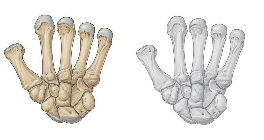
joint during wrist flexion-extension (FE) was investigated                                                                           Metacarpals
through noninvasive markerless optical tracking method.
Experiments with 25 healthy uninjured subjects have validated
the feasibility and precision of this improved kinematic model
and provide the justification of translational rotation axes
through nonlinear regression quantitatively.

                              II. M ETHODS

A. Conventional Model of the Upper Limb
   Given the assumptions that the skeleton of human body is                                                 Trapezoid                                              Hamate
comprised of rigid bone segments which are linked by fric-                                                                           Distal Carpal Row
                                                                                                             Trapezium                                             Capitate
tionless and universal joints, conventional kinematic model of
the upper limb were introduced to approximate the movement                                                                                                         Pisiform
                                                                                                                   Scaphoid           Proximal Carpal Row
of human body in terms of ranges of motion (ROMs) and                                                                                                           Triquetrum
degrees of freedom (DOFs).                                                                                   Radiocarpal Joint                                     Lunate
   The upper limb includes three rigid segments which are
anatomically described as the upper arm, the forearm and
the hand (considered as a single segment) respectively. Three                                          Fig. 2. Volar view of the carpal and metacarpal bones of the left hand in
universal joints link these segments which are the shoulder,                                           functional neutral wrist position [18]. With consistent kinematic behavior
the elbow and the wrist joint [10]. With the assumptions                                               constrained by carpal row alignment, wrist motion occurs as the combination
                                                                                                       movement of radiocarpal and midcarpal joints with unfixed rotation axes
that only rotational motion occurs in these joints, mechanical                                         within the capitate.
equilibrium equations can be established and conventional
kinematic model for upper limb with a total of 7 DOFs
is proposed, as shown in Fig. 1. The base of conventional                                              B. Carpal Kinematic Behavior in Wrist Motion
coordinate system {0} is located in the midway between                                                    The carpus region is comprised of eight dexterous and
shoulders and three frames are located at the center of the                                            intricately shaped carpal bones which articulate with each
complex joint shoulder. The human wrist is considered as                                               other complexly and interplay with the metacarpal bones and
a universal joint with 2 DOFs: abduction-adduction (radio-                                             the distal radio-ulnar joint. From volar view of a left wrist,
ulnar deviation, RUD) (X6 Y6 Z6 ) and FE (X7 Y7 Z7 ). The                                              as shown in Fig. 2, those carpal bones are arranged into the
end-effector frame {8} is located at the extended fingertips                                           proximal row and the distal row. From the anterior view of
as illustrated in Fig. 1. Therefore, the position and orientation                                      the proximal row, scaphoid, lunate, triquetrum and pisiform
of the end-effector (human hand) can be calculated from                                                are arranged from lateral to medial. The trapezium, trapezoid,
forward kinematics and the angular movement in joint space                                             capitate and hamate make up the distal row accordingly from
can be approximated through inverse kinematics.                                                        lateral to medial [19].
                                                                                                          Constrained by carpal ligaments and combined with distinct
                               {0}            X0                                                       geometric articulation, each carpal bone has six DOFs,
Circumduction
                  Flexion                                                                              enabling a virtually hemisphere of the wrist motion and
                                                       Y2
                  Extension Y0                                    X2                                   the complexity of carpal kinematics. Therefore, it is difficult
                                     Z0                                                                to describe the complete wrist motion precisely based on
                                            θ3              θ2         X1,Y3,Z2
                     Abduction
                                                          {1,2,3}                                      individual carpal bone kinematic behavior [17]. According
                  Adduction      Y1,Z3        θ1
                                                            X3,Z1
                                                                                                       to the anatomical basis of clinical practice, radiocarpal joint,
     L1             Flexion - Extension                                                                intercarpal joint (including joint of proximal row, midcarpal
                                                  L1
                                                                 X5,Y4                                 joint and joint of distal row) and carpometacarpal joint
                     Abduction                    {4,5}
                                                                                                       comprise the overall wrist joints [18]. Previous studies have
                                                             θ5        L2        Y7,Z6
                       Adduction                    θ4                                                 explained the rationale of simplifying the wrist motion into
                                                                            θ6             Y8
                                          Y5,Z4           X4,Z5                       L3
                                                                                                       movement at radiocarpal and midcarpal joints, based on
             L2                                                   {6,7}
                                                                                 θ7         {8}        the segments of proximal and distal carpal rows which are
 Flexion                             Supination             X6,Z7
                      L3                                                X7,Y6                          regarded as rigid and tight structure [19], [20]. The radiocarpal
 Extension                           Pronation                                        Z8          X8
                                                                                                       joint is a typical condyloid joint with two axes formed
                                                                                                       between the proximal row and the distal end of the radius,
Fig. 1. Conventional model of the upper limb [10]. The right upper limb
is modeled as three rigid segments linked by three universal joints which                              allowing biaxial movement of FE, abduction-adduction and
are the shoulder, the elbow and the wrist joint, denoted as {1}, {4} and                               circumduction. Carpal bones within the same carpal row
{6} respectively. Position and orientation of the end-effector is described in                         which are reinforced by ligaments exhibit consistent kinematic
coordinate frame {8} with respect to base coordinate frame {0}. 7 DOFs
movements of the upper limb are described through rotation angles θi                                   behavior, resulting virtually no relative movement at both
between consecutive frames.                                                                            proximal and distal joint [20]. Therefore, the movement
TABLE I
           D-H PARAMETERS OF THE IMPROVED MODEL

 i          αi−1      ai−1      di         θi        βi

 1          0         0         0          90◦

 2          90◦       0         d2         0

 3          −90◦      0         0          θ3        β3 −90◦

 4          90◦       0         0          θ4        β4

 5          0         a4        0          0

at intercarpal joints is together with radiocarpal actuated
by the same muscle, and is limited in midcarpal joint.
Based on anatomical characteristics and rational simplified
segments of the carpus, the sophisticated wrist motion can be
described as FE in the frontal plane, RUD in the sagittal plane
and circumduction, which mostly occur in the combination
movement of radiocarpal and midcarpal joints.
   Furthermore, the capitate is referred as the keystone of
carpus in distal row, and there is relatively minimal movement
between capitate and the third metacarpal distally. The capitate
also exhibits articular engagement with the scaphoid and
lunate proximally [20]. From both clinical function and
biomechanics point of view, the capitate indicates wrist           Fig. 3. Improved kinematic model of wrist motion is illustrated in volar
motion due to its prominent position and it is reasonable          view of right wrist. With respect to base coordinate system {0}, position and
to locate rotation axes within the capitate during wrist FE        orientation of the end-effector is described in coordinate frame {5} which
                                                                   is located within the plane defined by three fingertips. 2 DOFs movements
and RUD.                                                           of the wrist are described through rotation angles in coordinate frame {3}
   According to the conventional model, the coordinate frame       and {4} which indicate angles in RUD and FE respectively. Translation
is modeled as a universal joint with 2 DOFs. Only rotational       parameter d2 indicates the variable location of rotation center for global
                                                                   wrist motion.
motion about the pivot point can be described while linear
displacement along the axes is excluded from the conventional
kinematic model. However, both in vitro and in vivo studies
on carpal bone kinematics during wrist motion demonstrated         the origin of improved coordinate system locates within the
that the center of carpal rotation is not fixed in the proximal    radiocarpal joint, at the proximal articular lunate surface for
pole of the capitate. Variations in the location of pivot point    radius (as in Fig. 3). The positive X0 axis parallels to the
and evident measurable translation in carpal bones were            radial long axis and points distally. The positive Y0 axis is
reported [14], [15]. The kinematics of FE and RUD of the           directed ulnarly through the radial styloid and is perpendicular
human wrist is much more sophisticated and exhibits distinct       to the X0 axis. The coordinate system {1} shares the same
carpal mechanisms, rather than being modeled as a simplified       origin with {0} and rotates about Z1 axis for 90◦ from {0},
fixed hinge or simple joint as indicated by conventional model     according to the right-hand rule. The consistent origins of the
of the upper limb.                                                 coordinate system {2}, {3} and {4} are located within the
                                                                   capitate in initial configuration (no movement in FE or RUD),
C. Improved Kinematic Model of Wrist Motion                        as the indicator of the center of global wrist motion. Due to
   Compared with conventional model of the upper limb              the fact that the relative motion between the third metacarpal
(see Fig. 1) which illustrates that the carpal rotation occurs     and capitate is clinically negligible and the mounting fixture
about a single pivot point and wrist joints act like universal     rigidly constrains the middle finger with the palm (as in
joints, the proposed improved model (see Fig. 3) introduces        Fig. 1), the X3,4,5 and Z2 axes coincide with the straight
a prismatic joint to incorporate the 2 DOFs revolute joints,       line from O2 to middle fingertip O5 distally. The translation
locates the rotation center and describes the translational        along the Z2 axis is denoted as d2 , representing the variation
behavior of the axes in a more precise manner. It presents         in the location of rotation center for global wrist motion.
a biomechanical rational description of the carpal behavior        The positive X2 and Y3 axes coincide with Y0 initially. The
and more accurate estimation of the position and orientation       positive Z3 axis represents the rotation axis for RUD volarly.
of the end-effector (fingertip) for wrist kinematics and upper     The angle β3 of RUD (positive in ulnar deviation) derives
limb movement.                                                     from rotation θ3 around Z3 axis (as in Table I). The coordinate
   According to Denavit-Hartenberg (D-H) convention [21],          system {4} rotates about X3 axis for 90◦ from {3}. The
positive Z4 axis indicates the rotation axis for FE radially of the middle fingertip in the coordinate system {L}. The XL
and the angle θ4 equals to β4 which is positive in flexion. axis lies horizontally and parallels to the edge of the device
The coordinate system {5} is located within the plane defined and Y0 axis in the wrist. The positive YL axis is perpendicular
by index, middle and ring fingertips which is coincident with to the plane X0 Y0 and is directed volarly.
volar plane due to the constraint fixture. It represents the
position and orientation of the end-effector.
D. Kinematics Analysis of the Improved Model
1) Forward kinematics: The improved kinematic model
introduces a prismatic joint (as joint 2 in Fig. 3) to incorporate
the revolute joints (as joint 3,4 in Fig. 3) and describes the
carpal behavior during wrist motion based on biomechanical
rationale. The general transformation matrix for coordinate
system {i} with respect to {i − 1} is given by
i−1
i T =RotX (αi−1 ) T ransX (ai−1 ) RotZ (θi ) T ransZ (di )
cθi −sθi 0 ai−1
sθi cαi−1 cθi cαi−1 −sαi−1 −sαi−1 di
= Fig. 4. Position and orientation of coordinate frame {5} with respect to
sθi sαi−1 cθi sαi−1 cαi−1 cαi−1 di {L} are recorded via Leap Motion. The homogeneous transformation matrix
0 0 0 1 linking {L} and {0} is derived from experimental configuration.
(1)
where cθi and sθi represent cos θi and sin θi respectively, The posture data of the end-effector should be transformed
RotZ (Θ) and T ransQ (q) refer to rotational operators and into the improved model for inverse kinematics calculation.
translational operators respectively. The forward kinematics Given the optical sensor coordinate system, the origin
of the improved model derives from the general homogeneous coordinate frame and the rotation matrix, denoted as {L},
transformation and the D-H parameters. The transformation {0} and R (θ) respectively, the homogeneous transformation
matrices between two successive joints are calculated as: matrix which links the two coordinate system is described by
0 0 −1
0 −1 0 0 1 0 0 0 0 0
0 L R (θ) PLORG 0 −1 0 0
0
1 0 0 0 1
0 0 −1 −d2 LT = 0 1 L R (θ) =
1T = 0 T = 0 1 0
2
0 1 0 0 1 0 0
0 0 0 1 0 0 0 1 (4)
where 0 PLORG represents the location of origin OL with
c3 −s3 0 0
c4 −s4 0 0
respect to the coordinate system {0} which is measured
0 0 1 0 0 0 −1 0 according to the experimental configuration. The discrete
2 3
3 T = −s
T = position and orientation of the end-effector {5} tracked by
3 −c3 0 0 4 s4 c4 0 0
0 0 0 1 0 0 0 1 the optical sensor are described with respect to the coordinate
system {L} and denoted as L 5 T . Homogeneous transformation
1
0 0 a4
is applied for the detected posture with respect to the origin
0 1 0 0 coordinate system {0}:
4
5T = 0
0
0 1 0 5T = 0L T L
5T
0 0 0 1
(2)
nx ox ax px
To determine the posture of the end-effector in the improved ny (5)
oy ay py
model, the forward kinematics with respect to the origin =
nz
oz az pz
coordinate system {0} is calculated as: 0 0 0 1
0
5T = 01 T 12 T 23 T 34 T 45 T According to the results derived from forward kinematics
described in (3), the angle θ4 in FE, θ3 , β3 in RUD and the
−s3 c4 s3 s4 c3 d2 − a4 s3 c4 translation d2 can be calculated from the tracked data:
(3)
c3 c4 −c3 s4 s3 a4 c3 c4
=
s4
. θ4 = β4 = arcsin (pz /a4 ) (6)
c4 0 a4 s4
0 0 0 1 π
θ3 = arcsin (ay ) , β3 = θ3 + (7)
2
2) Inverse kinematics: According to the posture of the end-
d2 = px − a4 nx (8)
effector detected through optical sensor in Cartesian space,
the inverse kinematics determines the rotation angle and axes Therefore, the wrist rotation angle in FE and RUD with
location in joint space during carpal motion. As illustrated in respect to neutral position can be estimated based on the
Fig. 4, the sensor detects the discrete position and orientation posture of upper extremity. The translation parameter d2indicates the variation in carpal axes and justifies that the Customized Finger
wrist joint can not be modeled as a simplified universal joint Extension Orthosis
due to nonnegligible linear translation.
3) Coupled joints fitting: The evident translation along
carpal axis is closely related to coupled carpal rotation. Previ-
ous study has demonstrated that statistically consistent carpal Static Beam
kinematic behavior can be found from different subjects [20].
Therefore, a model parameter fitting process was applied Customized
Shin Guards
to find accurate numerical equation between wrist rotation
Leap Motion
center (described by d2 in prismatic joint) and coupled carpal
sensor
angular motion (β3 in RUD and β4 in FE). A nonlinear
regression model was established to fit observed data set
Fig. 5. Experiment apparatuses and configuration including customized
points (xi , yi , zi ), where (x, y, z) represented (β3 , β4 , d2 ) and finger extension orthosis and shin guards which constrain undesired
i = 1, 2, . . . , N , to a nonlinear function which was a binary movement in the hand and forearm.
quadric polynomial described as
a1 + a3 x + a5 y + a7 x2 + a9 y 2 + a11 xy between estimation and observation
ẑ = (9)
1 + a2 x + a4 y + a6 x2 + a8 y 2 + a10 xy SSR SSE
R2 = SST =1− SST
where unknown parameters aj (j = 1, . . . , 10) were opti-
N N
mized through Simple Genetic Algorithm (SGA) to minimize P
[wi (ẑi −z̄i )2 ]
P
[wi (zi −ẑi )2 ] (13)
the sum of square error (SSE) between observation and = i=1 = 1 − i=1
N N
estimation data sets P
[wi (zi −z̄i )2 ]
P
[wi (zi −z̄i )2 ]
i=1 i=1
N
X N h
X i
2
SSE = ε2i = wi (zi − ẑi ) (10) SSR represents the regression sum of squares. SST represents
i=1 i=1 total sum of squares which is proportional to the variance of
the data. The R2 ranges from 0 to 1 statistically and R2 of
where εi was residual term and wi was the weight set to be 1.
1 indicates that the estimation fits the observation perfectly.
Possible solutions of aj were encoded into the chromosome
through vectors of real number coding and initial population E. Participants and Experimental Procedure
size was set to be 20 empirically. Parent chromosome were
Experiments have been designed and conducted to track
chosen to mate through random selection and the crossover
human upper extremity movement and validate the proposed
operators were developed by method of uniform crossover
improved kinematic model. After obtaining informed consent,
and the chance of crossover was set to be 0.85 empirically.
25 healthy young subjects aged from 21 to 27 (4 females,
Generally the rate of mutation was set to be 0.005 which was
age 22.8 ± 1.3 and 21 males, age 24.6 ± 1.2) were recruited
relatively low in consideration of the convergence rate and
to participate in the experiment. All subjects show no
computational costs for the overall algorithm performance.
radiographic or history evidence of upper extremity pathology
Measures of goodness of fit were applied to describe the or chronic disease that might affect motion of distal arm. The
fitness of the estimated parameters aj with the observation. movement of right wrist of each subject was tracked by optical
The standardized residual ri derives from εi and average sensor and investigated in this study. All subjects exhibit
residual ε̄ right hand dominance following the Edinburgh-handedness
εi
ri = s (11) inventory [22]. No ethic approval was required.
N
1
P
(εi − ε̄)
2 The movement of distal arm for each subject was recorded
N −1
i=1 during wrist FE motion through the Leap Motion sensor. The
Leap Motion sensor offers novel solutions to track the motion
The root mean square error (RMSE) indicates the deviation of human hands and fingers and record discrete positions and
between estimated and observed values and is generally gestures of distal arm within intimate proximity of operating
considered as a scale dependent residual metric space [23], [24], [25]. Study addressing the tracking accuracy
√ p and robustness of the optical device has reported that an
RM SE = M SE = SSE/N overall average accuracy of 0.7 mm was achieved among
s (12) static and dynamic measurement. Deviation between desired
N h
and measured positions was less than 0.2 mm, independent
i
1
P 2
= N wi (zi − ẑi )
i=1 of axis under experimental condition [26]. Another study
revealed that standard deviation between 0.0081 mm and 0.49
The coefficient of determination, denoted as R2 , indicates mm was obtained [27]. It indicated that the Leap Motion
the goodness of estimation in reflecting the variation of sensor is a reasonably precise and reliable tracking system
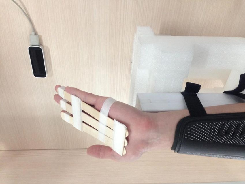
observations and is calculated as the square of the correlation dedicated to detecting the motion of human hands.As illustrated in Fig. 5, all volunteers were seated beside 35
the experiment table and placed the forearms onto the axially Observation
static beam, paralleling to the long axis of the beam with 30 Estimation
Absolute Residual
the elbow joint flexed about 90◦ and the shoulder joint
Translation Value (mm)
25
abducted about 45◦ . The forearms were constrained by
customized shin guards and constantly fixed at the static beam, 20
resulting no pronation-supination (PS) motion in forearms.
Customized finger extension orthosis was fixed on subjects’ 15
palm, constraining the relative movement in interphalangeal
joints, metacarpophalangeal joints and carpometacarpal joints 10
of the index, middle and ring fingers which were extended
and coincident within volar plane of the hand. The middle 5
finger was specifically fixed distally along the radial long
axis, ensuring that the middle finger is collinear with the 0
0 500 1000 1500 2000 2500 3000 3500 4000
Y axis of capitate which is defined according to ISB Tracked Points
recommendation [28]. The functional neutral position of the
wrist relative to the radius was defined according to ISB Fig. 7. Results of nonlinear regression between translation parameter d2
and estimated wrist angles β3,4 based on nine subjects’ tracking data.
recommendation and the neutral of the forearm was defined
as in neutral PS position. In addition to neutral position,
subjects were instructed to rotate the wrists smoothly within
range from 30◦ of flexion to 10◦ of extension. The trajectories wrist extension than that location during wrist flexion. A
of tracked hands were illustrated by the visualizer application linear regression between d2 and β4 in FE was conducted.
simultaneously. Subjects were instructed to complete 10 The Spearman’s rank correlation coefficient of -0.97 (p =
cycles in FE motion slowly within 40 seconds ensuring 6.1e−205 ) indicated that statically high correlation between d2
accurate tracking. One typical cycle movement included and β4 was exhibited and the negative correlation showed that
moving from neutral to extension, then to flexion and back d2 tends to decrease when β4 increases. It can be concluded
to neutral finally. that carpal joints can not be modeled as simple joints and
carpal rotation axes move distally during wrist extension
III. R ESULTS and move proximally during wrist flexion. These results are
consistent with previous biomechanical study [20].
Experimental data were extracted and illustrated to validate
the feasibility and accuracy of the improved model. As shown Tracking data of nine subjects (two females, age 22.0 ± 1.4
in Fig. 6, the translation parameter d2 indicates that the and seven males, age 25.0 ± 1.4) were chosen randomly for
location of wrist rotation axes was not fixed in single point. model parameter fitting process. Data of β3,4 derived from
The value of d2 changes evidently during one cycle in FE inverse kinematics were grouped together to fit the nonlinear
motion. Compared with the angle in FE, a more distal location function for accurate estimation of d2 , as described in (7).
of the rotation axes illustrated by larger d2 was noted during Unknown parameters aj (j = 1, . . . , 10) were optimized
through SGA and the fitting results are illustrated in Fig. 7
3
40 Smoothed Residual
Standardized Residual (mm)
Estimated Translation Value (mm)
spearmanr = -0.97; p = 6.1e-205 2
38
1
36
34 0
32 1
30
2
28
3
26 10 15 20 25 30 35
0.2 0.1 0.0 0.1 0.2 0.3 0.4 0.5 0.6
Estimation in FE (rad) Estimated Translation (mm)
Fig. 6. Calculation of measurable translation parameter d2 in one cycle Fig. 8. Interpretation of regression performance with smoothed standardized
FE movement. residuals.kinematics of uninjured subjects. Differences of in vivo carpal
behavior and distal arm biomechanism among subjects are
statistically negligible and differences between right and
left wrists are not significant [20]. In addition, differences
in location of rotation axes demonstrated between males
and females are related to subject anatomical size [17]. It
is suggested that wrist motion parameters are independent
from gender and the locations of floating axes are related to
carpal bones volume and the neutral centroid location [15],
[20]. Therefore, based on previous evidence addressing
consistent individual carpal kinematics, it is rational to
conduct confirmatory experiments according to the stated
participant recruitment criteria.
B. Measurement of Carpal Kinematics
Evident differences between in vivo and in vitro experi-
mental techniques are reported from previous biomechanical
Fig. 9. Residuals derived from calculated d2 and estimated dˆ2 among studies. For In vitro studies, reflective pins and markers
sixteen subjects in box plots.
are implanted into carpal bones [14], [29]. This invasive
implant techniques may alter kinematic characteristics of
overlying tendons and surrounding soft tissue. Exterior
and described as
constrains imposed by kinematic markers would interfere
dˆ2 = individual carpal bones motion and mechanical interaction
18.00−290.93β3 −29.46β4 +2563.09β3 2 +37.01β4 2 −606.53β3 β4
1−10.60β3 −2.23β4 +94.62β3 2 +2.12β4 2 −25.75β3 β4 within carpus. Normal muscular contraction and tendon
(14) loading are simulated by attached mechanism where uncertain
The standardized residual ri was calculated and analyzed deviation from in vivo simulation would occur inevitably and
by locally weighted scatterplot smoothing (LOWESS). As minute changes in muscular dynamics may affect wrist motion
shown in Fig. 8, the residual plot is nearly symmetrically significantly [14]. Computed tomography (CT) scanning is
distributed and the scatter points are clustered around the line commonly adopted by in vivo studies and issues addressing
where ri = 0. Besides ri , values of SSE, RMSE, correlation safe radiation exposure may limit the duration of scanning
coefficient (R) and R2 are determined as 7565.68, 1.35, 0.96 protocol and the number of experimental samples [17],
and 0.93 respectively. All these mentioned statistical results [30]. Compared with implanted measurement and scanning
justified the accuracy of the fitting process and illustrate techniques, the proposed noninvasive markerless method
quantitative connections between rotation axes and coupled offers more applicable distal arm optical tracking solution for
wrist angles. human-robot interaction and restores natural carpus motion
Tracking data of the left sixteen subjects (2 females, age authentically. In addition, statistically negligible differences
23.5 ± 0.7 and 14 males, age 24.8 ± 1.5) were prepared were reported between static and dynamic wrist motion and
to verify the fitted equation (14). The wrist angle β3,4 for the tracking data derived from static scanning procedure
each subjects were calculated from inverse kinematics of approximates dynamic passive carpal kinematics. It can be
the improved model and were used to estimate d2 through concluded that carpal bone kinematics can be measured
equation (14). The estimation values dˆ2 were taken in com- either statically or dynamically [16]. Therefore, it is rational
parison with the calculation of d2 derived from equation (8) to conduct the proposed optical tracking procedure during
to illustrate the accuracy of improved model among sixteen relatively slow movement pace.
subjects. As illustrated in Fig. 9, overall residual values among
subjects fell in the range from -12 mm to 10 mm. The overall C. Implementation Rationale for Robotic Neurorehabilitation
average deviation between dˆ2 and d2 across all subjects was Functional assessment for neurorehabilitation and mechan-
−0.39 ± 3.14 mm and average percentage error across all ical implementation for robotic rehabilitation devices are
subjects was 8.00 ± 3.27%. It can be concluded that the fundamentally based on biomenchanically rational kinematic
proposed equation estimated the location of unfixed rotation model of human body [6], [7]. Under the assumption that only
axes accurately and the results were consistent among twenty rotation motions exist in decoupled carpal joints, conventional
subjects statistically. kinematic model of the upper limb fails to estimate the posture
of end-effector and wrist joint precisely. This inevitable limi-
IV. DISCUSSION
tation and undesired misalignment between joint kinematics
A. Consistency of Wrist Biomechanics and robotic evaluation will bring unreliable parameters for re-
Experiments recruited 25 healthy young subjects without habilitation assessment in joint space. The proposed improved
distal arm pathology, including 4 females and 21 males. kinematic model of wrist motion has justified the existence
Previous study has presented high uniformity between carpal of measurable unfixed axes in carpal rotation and providedaccurate estimation of axes location based on coupled wrist [9] K. Wang, S. Li, C. Xu, and N. Yu, “An extended kinematic model
angles. Therefore, kinematic assessment of distal arms in for arm rehabilitation training and assessment,” in 2016 International
Conference on Advanced Robotics and Mechatronics (ICARM). IEEE,
joint space is feasible and effective based on the accurate 2016, pp. 117–121.
model, providing objective and quantitative measurement for [10] M. Babaiasl, S. H. Mahdioun, P. Jaryani, and M. Yazdani, “A review
neurorehabilitation. In addition, D-H parameter notation is a of technological and clinical aspects of robot-aided rehabilitation of
upper-extremity after stroke,” Disabil. Rehabil. Assist. Technol., vol. 11,
generic and standardized robotic notation [8]. The proposed no. 4, pp. 263–280, 2016.
kinematic model of wrist motion can be directly adopted in [11] H. Patel, G. O’Neill, and P. Artemiadis, “On the effect of muscular
robotic fields and is essential for robotic implementation of cocontraction on the 3-D human arm impedance,” IEEE Trans. Biomed.
Eng., vol. 61, no. 10, pp. 2602–2608, 2014.
exoskeleton and robotic neurorehabilitation evaluation. [12] D. Formica, S. K. Charles, L. Zollo, E. Guglielmelli, N. Hogan, and H. I.
Krebs, “The passive stiffness of the wrist and forearm,” J. Neurophysiol.,
V. CONCLUSIONS vol. 108, no. 4, pp. 1158–1166, 2012.
Accurate evaluation of upper extremity kinematics are [13] A. Kecskeméthy and A. Weinberg, “An improved elasto-kinematic
model of the human forearm for biofidelic medical diagnosis,” Multi-
keys for better understanding of physical human-robot body. Syst. Dyn., vol. 14, no. 1, pp. 1–21, 2005.
interactions to deliver robotic neurorehabilitation and as- [14] R. M. Patterson, C. L. Nicodemus, S. F. Viegas, K. W. Elder, and
sistance. In specific, realistic biomechanical modeling of J. Rosenblatt, “High-speed, three-dimensional kinematic analysis of
the normal wrist,” J. Hand. Surg., vol. 23, no. 3, pp. 446–453, 1998.
human wrist is crucial for ergonomic designs of assistive [15] C. Neu, J. Crisco, and S. Wolfe, “In vivo kinematic behavior of
exoskeletons and human-robot collaboration. In this study, the radio-capitate joint during wrist flexion–extension and radio-ulnar
the proposed improved kinematic model has justified the deviation,” J. Biomech., vol. 34, no. 11, pp. 1429–1438, 2001.
[16] M. Foumani, S. Strackee, R. Jonges, L. Blankevoort, A. Zwinderman,
existence of measurable unfixed axes in carpal rotation which B. Carelsen, and G. Streekstra, “In-vivo three-dimensional carpal bone
supports prior studies indicate that inevitable misalignment kinematics during flexion–extension and radio–ulnar deviation of the
and oversimplification between robotic representation and wrist: Dynamic motion versus step-wise static wrist positions,” J.
Biomech., vol. 42, no. 16, pp. 2664–2671, 2009.
human joints will occur. The accurate estimation of axes [17] J. C. Coburn, M. A. Upal, and J. J. Crisco, “Coordinate systems for
location are achieved through coupled wrist angles with the carpal bones of the wrist,” J. Biomech., vol. 40, no. 1, pp. 203–209,
nonlinear regression. Experiments with uninjured subjects 2007.
[18] S. Standring, Gray’s anatomy e-book: the anatomical basis of clinical
have validated the improved model through optical tracking practice. Elsevier Health Sciences, 2015.
method and numerical optimization based on robotic model- [19] R. Drake, A. W. Vogl, and A. W. Mitchell, Gray’s anatomy for students.
ing. Therefore, kinematic assessment of distal arms in joint Elsevier Health Sciences, 2014.
[20] S. W. Wolfe, C. Neu, and J. J. Crisco, “In vivo scaphoid, lunate, and
space is feasible and effective based on this proposed model, capitate kinematics in flexion and in extension,” J. Hand. Surg., vol. 25,
enabling quantitative implementation for physical human- no. 5, pp. 860–869, 2000.
robot interaction and robotic neurorehabilitation. [21] J. Denavit and R. S. Hartenberg, “A kinematic notation for lower-pair
mechanisms based on matrices.” J. Appl. Mech., vol. 22, pp. 215–221,
R EFERENCES 1955.
[22] R. C. Oldfield, “The assessment and analysis of handedness: the
[1] V. Klamroth-Marganska, J. Blanco, K. Campen, A. Curt, V. Dietz, edinburgh inventory,” Neuropsychologia, vol. 9, no. 1, pp. 97–113,
T. Ettlin, M. Felder, B. Fellinghauer, M. Guidali, A. Kollmar, et al., 1971.
“Three-dimensional, task-specific robot therapy of the arm after stroke: [23] M. Iosa, G. Morone, A. Fusco, M. Castagnoli, F. R. Fusco, L. Pratesi,
a multicentre, parallel-group randomised trial,” Lancet. Neurol., vol. 13, and S. Paolucci, “Leap motion controlled videogame-based therapy
no. 2, pp. 159–166, 2014. for rehabilitation of elderly patients with subacute stroke: a feasibility
[2] J.-C. Metzger, O. Lambercy, A. Califfi, D. Dinacci, C. Petrillo, pilot study,” Top. Stroke Rehabil., vol. 22, no. 4, pp. 306–316, 2015.
P. Rossi, F. M. Conti, and R. Gassert, “Assessment-driven selection [24] N. Yu, C. Xu, H. Li, K. Wang, L. Wang, and J. Liu, “Fusion of haptic
and adaptation of exercise difficulty in robot-assisted therapy: a pilot and gesture sensors for rehabilitation of bimanual coordination and
study with a hand rehabilitation robot,” J. Neuroeng. Rehabil., vol. 11, dexterous manipulation,” Sensors, vol. 16, no. 3, p. 395, 2016.
no. 1, p. 1, 2014. [25] C. Xu, H. Li, K. Wang, J. Liu, and N. Yu, “A bilateral rehabilitation
[3] P. Maciejasz, J. Eschweiler, K. Gerlach-Hahn, A. Jansen-Troy, and method for arm coordination and manipulation function with gesture
S. Leonhardt, “A survey on robotic devices for upper limb rehabilitation,” and haptic interfaces,” in Proc. IEEE Int. Conf. on Robotics and
J. Neuroeng. Rehabil., vol. 11, no. 1, p. 1, 2014. Biomimetics (ROBIO), Zhuhai, China, Dec 2015, pp. 309–313.
[4] S. F. Atashzar, M. Shahbazi, O. Samotus, M. Tavakoli, M. S. Jog, [26] F. Weichert, D. Bachmann, B. Rudak, and D. Fisseler, “Analysis of
and R. V. Patel, “Characterization of upper-limb pathological tremors: the accuracy and robustness of the leap motion controller,” Sensors,
application to design of an augmented haptic rehabilitation system,” vol. 13, no. 5, pp. 6380–6393, 2013.
IEEE Journal of Selected Topics in Signal Processing, vol. 10, no. 5, [27] J. Guna, G. Jakus, M. Pogačnik, S. Tomažič, and J. Sodnik, “An
pp. 888–903, 2016. analysis of the precision and reliability of the leap motion sensor and
[5] C. Xu, S. Li, K. Wang, Z. Hou, and N. Yu, “Quantitative assessment its suitability for static and dynamic tracking,” Sensors, vol. 14, no. 2,
of paretic limb dexterity and interlimb coordination during bilateral pp. 3702–3720, 2014.
arm rehabilitation training,” in 2017 International Conference on [28] G. Wu, F. C. Van der Helm, H. D. Veeger, M. Makhsous, P. Van Roy,
Rehabilitation Robotics (ICORR). IEEE, 2017, pp. 634–639. C. Anglin, J. Nagels, A. R. Karduna, K. McQuade, X. Wang, et al.,
[6] M. D. Rinderknecht, O. Lambercy, V. Raible, I. Büsching, A. Sehle, “ISB recommendation on definitions of joint coordinate systems of
J. Liepert, and R. Gassert, “Reliability, validity, and clinical feasibility various joints for the reporting of human joint motion part ii: shoulder,
of a rapid and objective assessment of post-stroke deficits in hand elbow, wrist and hand,” J. Biomech., vol. 38, no. 5, pp. 981–992, 2005.
proprioception,” Journal of neuroengineering and rehabilitation, vol. 15, [29] C. Neu, R. McGovern, and J. Crisco, “Kinematic accuracy of three
no. 1, p. 47, 2018. surface registration methods in a three-dimensional wrist bone study,”
[7] T. Nef, M. Guidali, and R. Riener, “ARMin III–arm therapy exoskeleton J. Biomech. Eng., vol. 122, no. 5, pp. 528–533, 2000.
with an ergonomic shoulder actuation,” Appl. Bionics. Biomech., vol. 6, [30] N. Yu, N. Estévez, M.-C. Hepp-Reymond, S. S. Kollias, and R. Riener,
no. 2, pp. 127–142, 2009. “fMRI assessment of upper extremity related brain activation with an
[8] V. J. Santos and F. J. Valero-Cuevas, “Reported anatomical variability mri-compatible manipulandum,” Int. J. Comput. Assist. Radiol. Surg.,
naturally leads to multimodal distributions of denavit-hartenberg vol. 6, no. 3, pp. 447–455, 2011.
parameters for the human thumb,” IEEE Trans. Biomed. Eng., vol. 53,
no. 2, pp. 155–163, 2006.You can also read