Embedded Obfuscated Barcodes for Identication of Genuine Additive Manufactured Parts
←
→
Page content transcription
If your browser does not render page correctly, please read the page content below
Embedded Obfuscated Barcodes for Identification
of Genuine Additive Manufactured Parts
Fei Chen
New York University Tandon School of Engineering
DINESH PINISETTY ( dpinisetty@csum.edu )
California State University Maritime Academy: California Maritime Academy https://orcid.org/0000-
0003-0931-034X
Nikhil Gupta
New York University Tandon School of Engineering
Research Article
Keywords: additive manufacturing, product security, barcodes, obfuscated codes, 3D printing
Posted Date: June 10th, 2021
DOI: https://doi.org/10.21203/rs.3.rs-592866/v1
License: This work is licensed under a Creative Commons Attribution 4.0 International License.
Read Full License
Page 1/22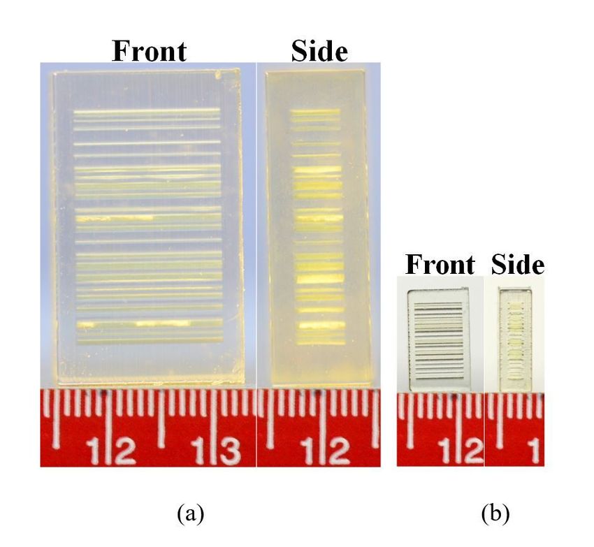
Abstract
Additive manufacturing (AM) has been adopted for manufacturing complex shaped highly customized
components for aerospace, automotive, and medical fields, where intellectual property protection and
counterfeit detection are major concerns. New technologies such as Blockchain have been promising in
supply chain authentication. However, AM due to layer-by-layer manufacturing process provides
opportunities of embedding information inside the part during manufacturing, which has been explored
recently to embed identification codes inside the parts. The present work studies the possibility of printing
a barcode inside the additively manufactured part and develops a scheme to obfuscate the code design
to read differently from different directions to enhance the security and protect the intellectual property.
The embedded three-dimensional codes are scanned using a micro-CT scan. This scheme of embedded
obfuscated codes proves to be a highly customizable and efficient process while securing product design
files.

1. Introduction
Additive manufacturing (AM) has evolved as one of the promising manufacturing technologies in
aerospace in medical sectors [1–3]. However, security of intellectual property (IP) and identification of
counterfeit and unauthorized products have always been an issue in aerospace and medical sectors [4–
6]. Cloud-based platforms have enabled sharing and collaboration for development of product designs;
however, security of information has been a concern for such systems due to increased attack surface [7].
The attack taxonomy has been studied in the available literature and shows several possible attack
vectors in the AM field [8]. Since AM is currently used for development and production of highly valued
parts such as aircraft and spacecraft components and patient specific medical device parts, security
concerns are amplified for this field [9–12]. The additively manufactured products are subjected to
cyberattacks, counterfeiting or other illegal activities, causing huge financial loss and safety concerns [10,
13–17]. Currently, there is very limited discussion on the effective solutions to secure AM and its
products. In the following Sect. 1.1, an overview of some of the anti-counterfeiting methods is presented
along with the possible implementation of these methods in AM and its products. It is evident that the
conventional security labels are highly subjected to removal-reapplication attacks, which will result in
severe losses. Our scheme of embedding “security labels” inside the product can reduce the risk of
security breach. Furthermore, we also propose a novel security strategy that is rooted in the design files to
prevent counterfeiting production by efficiently distinguishing the fake products from genuine ones [18].

1.1 Overview of current product authentication tools
Authentication technologies and security tools are essential to all genuine products and their legitimate IP
owners [19]. Anti-tamper devices, package and box seal, package sealing tapes are available for tamper
resistance, but once exposed, the product identity can be still stolen and reproduced for counterfeits.
Property marking is also made on the surface where products can be marked with security markers and
stamping products [20, 21]. These markers can be in fluorescence but transparent and only visible under
                                                  Page 2/22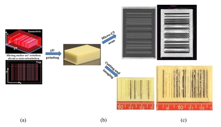
an UV light. However, this technique may be limited to protect high-value components with extremely
small sizes such as a microchip due to writing difficulty. In addition, traces of these UV markings may be
seen with naked eyes if not performed properly and subsequently removed by attackers. Other methods
like holographic label printing anti-counterfeiting approach enabled by laser holographic technology are
also used to prove product authenticity [20, 22]. ID card, passport, document laminates can be made
using holographic technology with multi-color fluorescing inks, optically variable ink (OVIs) and liquid
crystal solutions to create unique identifiable features [20, 22].

Credit cards and banknotes are designed to have holographic security labels on them which change
colors as they are tilted [20, 23]. However, these labels are still subjected to duplication, reproduction or
removal by attackers. Product serial numbers on a sticker label can be placed externally on the product
and help to distinguish a genuine product from a counterfeit one but they can be scratched off to prevent
product authentication or other logistic management [24]. For example, barcode or QR code labels are
attached on the outer surface of consumer products so that they can be identified with a code scanner.
This scanning system is favored by many businesses for high efficiency, productivity, and relatively low
cost [24, 25]. The small barcode can encode sufficient amounts of information in a visual pattern.
However, the tracking label can be damaged and lose its functionality. In addition, the radio-frequency
identification (RFID) tags, with or without an electronic chip, have been widely used in many applications
including warehouse logistics, product tracking in a supply chain, passports, and banknotes [23, 26]. In
many applications like identity cards, passports or credit cards, RFID tags with integrated circuits (ICs) are
used to prevent data theft and control access [26, 27]. An RFID tag or chip is more resistant to wearing
damage but is still subjected to be removed or disabled by attackers similar to other product
authentication labels.

1.2 Proposed AM product security approach
All the cybersecurity strategies can help to keep the product safe from counterfeiting, but once they are
breached, IP can be stolen, and counterfeits can be produced. Therefore, we propose a security approach
that protects the product at the design level, where parameters including printer capabilities, layer
resolution, scanning resolution are taken into consideration. The aforementioned authentication tools
and techniques can be subjected to damage at different levels. When applying these tools in AM and its
products, surface labeling such as security marking or label attachments are highly vulnerable to the
removal-reapplication attacks. Security labeling such as laser engraving tools can reduce the risks of
removal-reapplication attacks to some extent, but also make the security features visible and subject to
counterfeiting using 3D scanning reverse engineering. Therefore, in this work we study the possibility of
embedding security and authentication codes inside the component that is intended for 3D printing at the
product design level. Widely used barcodes are taken as an example in this study for the possibility of
embedding them in product design. Such embedded codes would not be visible from outside and cannot
be tempered.

Only by imaging techniques such as computed tomography (CT) scanning, the embedded features can
be visualized and confirmed for authenticity. In this work, we have provided an extensive description for
                                                   Page 3/22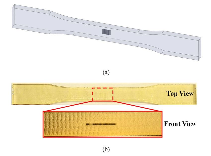
the CAD development with embedded features, the scanning and reading procedure, and further improved
complexity on the embedded features. The design strategies, as discussed in previous studies [15, 28–
31] were utilized to demonstrate the enhancement of product security by modifying the embedded
features such that a unique set of processing parameters are required to produce parts with the correct
embedded codes.

2. Design And Process Development
A barcode image representing the four letters “CMML” (that stands for “Composite Materials and
Mechanics Lab”) is selected and imported into a 3D modelling software SolidWorks 2019 to construct a
3D CAD model of a cuboid with embedded barcode, which is then used for AM.

2.1 Embedded barcode models
2.1.1 One-layer barcode
One-dimensional zebra-striped barcodes are typically used in the retail industry for commercial products
[32]. These 1D barcodes encode data only horizontally using black bars on a white background, which are
sufficient enough for storing information such as numbers or short tags. For a string field with more than
25 characters, however, they are insufficient, let alone a text area field that has a 30,000 characters’ limit
or URLs [32]. Despite their limited information storage capability, one dimensional barcodes are still
widely used for high feasibility of creating and reading [33].

Code 128 is one of the most widely used 1D barcodes in shipping and packaging industries as a product
identification code. Therefore, a code 128 is generated for the string character “CMML” using an online
conversion tool as shown in Fig. 1(a), which contains machine readable information (in black strips) and
human-readable text (in letters underneath) [33]. A 3D CAD model as shown in Fig. 1(b) is created in
SolidWorks 2019 by first importing the barcode image in Fig. 1(a) and then using the “Sketch” and
“Extruded Cut” functions to define contour, locations, and dimensions. The complete 1D barcode is
embedded within a solid prism at the same depth and 3D printed using VeroClear transparent
photopolymer for visualization of internal features as shown in Fig. 2. When imported in a Slicer program,
the STL model is scaled down and printed in different sizes using the Stratasys Objet30 Pro resin 3D
printer to evaluate possible miniaturization of using such codes. As depicted in Fig. 2, a part embedded
with a 1D barcode can be 3D printed as small as 10 × 6 × 3 mm3 in length × width × thickness and still
have a good visibility of the code to the naked eye. Smaller codes can be generated for reading through
imaging methods.

2.1.2 Mechanical Testing on one-layer barcode
Parts with embedded codes are evaluated for their mechanical properties and structural integrity. It is
expected that under the optimal design, with the security feature size minimized and properly positioned
inside the part, the parts’ original functionality will not be compromised.
                                                   Page 4/22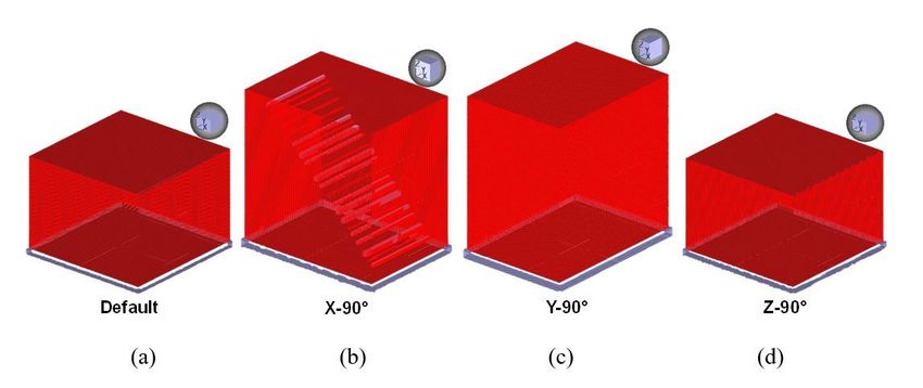
The standard tensile bar specimen geometry with embedded barcode feature is developed as shown in
Fig. 3(a), where the same barcode pattern in Fig. 1 is used here. The volume of “Extruded Cut” barcode is
7.85 mm3 as compared to 15739.09 mm3 for the entire solid tensile bar, which gives a volumetric ratio of
0.0499% between barcode and tensile bar as in the CAD program. The tensile bar files are used for 3D
printing using the Stratasys Objet30 Pro resin 3D printer and VeroClear photopolymer model material with
high printing resolution down to 16-microns layer thickness. Meanwhile a set of standard tensile bars
without any embedded codes are also printed using the same method to determine the baseline
properties. The 3D printed tensile bar with embedded barcode is shown in Fig. 3(b), where the embedded
barcode can be seen clearly from the front view. After visually validating the existing embedded barcodes,
which are printed with support material (Stratasys SUP706) rather than the model material, standard
tensile test is performed on 5 tensile specimens. Three tensile bars without embedded codes are also
tested for reference (fewer than 5 specimens were tested due to high consistency; deviation is less than
1%).

The processed tensile test results are plotted in Fig. 4 with representative data from both categories,
showing a close match between the stress-strain curves. The tensile properties are calculated and
summarized in Table 1, where embedded code specimens show on average only ~ 0.35% lower tensile
strength and ~ 0.39% lower modulus as compared to the reference specimens without embedded code.
Therefore, it can be safely concluded that an embedded tracking code such as the one used in Fig. 3
would not significantly affect the part’s tensile properties, and hence can be a promising scheme to
secure the product while preserving its strength and functionality.

                                                   Table 1
                      Tensile properties of both standard tensile specimens with and
                                        without embedded barcode.
                    Tensile Properties        Embedded Code           No Code (reference)

                    Ultimate Stress (MPa)     62.23 ± 0.91            62.45 ± 0.69

                    Modulus (GPa)             2.56 ± 0.14             2.57 ± 0.03

2.1.3 Multi-layer barcode
The same barcode representing “CMML” as in Fig. 1(a) is used to create the multi-layer barcode CAD
model in SolidWorks 2015 as shown in Fig. 5. Similarly, the barcode image was first imported in
SolidWorks and a total of 22 rectangular prisms were generated using the “Sketch” and “Extruded Cut”
functions to define contour, locations, and dimensions. These 22 prisms represent the barcode pattern
and are embedded at 22 different planes with distances equal to the white spacing between each black
stripe of the barcode, inside a larger rectangular prism that is 56 × 56 × 40 mm3 in length × width ×
thickness. The 22 rectangular prisms are 30 mm in length with their square sides equal to 0.6 × 0.6 mm2,
1.2 × 1.2 mm2, or 1.8 × 1.8 mm2, depending on the corresponding barcode stripe dimensions.

                                                  Page 5/22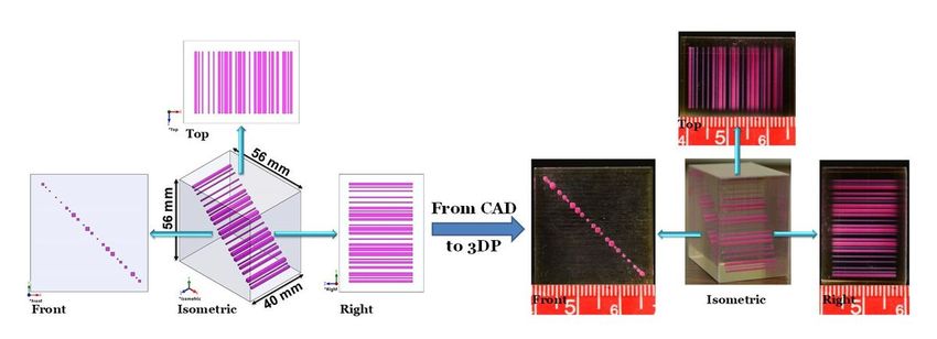
With careful placement, the top and right-side views can display the exact same barcode using the
multiple layers embedding scheme as depicted in Fig. 5. Distances between each stripe and their widths
are used to reconstruct the same barcode pattern on the side. By changing the thickness of each stripe,
the side pattern can be dramatically different, leading to different barcode reading, or simply a false
barcode. With the distributed layers of codes, it not only obfuscates the appearance of the 3D barcode,
but also reduces the stress concentration as compared to the one-layer barcode model.

Once exported as STL file (coarse resolution), the model is sent to the Stratasys J750 3D printer and 3D
printed using the multi-material 3D printing method (PolyJet), where the barcode volume is printed in red
using VeroMagenta photopolymer, and outside enclosure cuboid is printed using VeroClear photopolymer
for transparency as shown in Fig. 5.

2.2 Embedded obfuscating barcode models
The embedded tracking code can serve as a unique product signature by distinguishing itself from
counterfeiting products that do not have any embedded tracking codes. However, when the entire design
files are stolen, it is likely that expert attackers can use these design files to illegally reproduce parts with
comparable quality and the same tracking code information. Therefore, we have modified the design of
these embedded features such that they can be only printed correctly under a specific set of processing
parameters such as printing orientation. In this case, despite being stolen, attackers will need to invest
significant resources to determine the best combination of processing parameters to produce parts with
high quality and the sane tracking codes, which can effectively distinguish counterfeits from the genuine
products and protect the original rightful IP owner.

2.2.1 Obfuscating one-layer barcode
The embedded barcode feature can be modified with other 3D modelling features such as the surface
feature to secure the original product. Here a CAD modeling scheme is developed such that the embedded
barcode can only be 3D printed under a specific set of processing parameters (individual feature size,
resolution of STL file and direction of slicing), while other attempts will not generate parts with the
embedded barcode for an authentication process. In this way, attackers or other unauthorized users
cannot reproduce the part with the embedded tracking code easily without knowing the processing
parameters, which results in failure at passing the authentication steps.

The original CAD model for the barcode model is shown in Fig. 1(b), where the barcode stripes are
extruded inside a solid prism. This model is modified such that the barcode stripes are applied with the
“Extruded Surface” function inside the solid prism as shown in Fig. 6, so that it becomes an obfuscating
embedded barcode model. Each barcode stripe is represented with an open surface in the same
rectangular shape as the stripe. When these barcode stripes are performed with the “Extruded Surface”
instead of the “Extruded Cut” function, the model shows orientation-dependent slicing results.

                                                    Page 6/22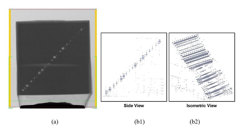
In the original CAD model, dimensions for the solid prism are 12 × 8 × 4 mm3, where the minimum width
of the bar stripe is 0.13 mm. However, depending on the printer resolution and capability, a scale factor
should be applied such that the minimum width of barcode stripe is a multiple of the printer layer
thickness. The modified CAD model is translated to a standard tessellated file format STL and saved in
coarse STL resolution, which is then imported to a slicer CatalystEX for FDM 3D printing. The minimum
layer thickness 0.178 mm is chosen for 3D printing using this printer, therefore, the minimum width of
stripe is scaled up to 0.178 mm with a scale factor of 1.37 applied to original CAD model dimensions, to
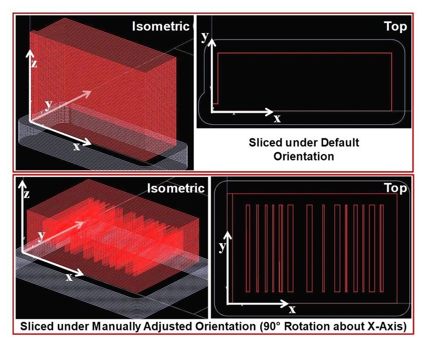
ensure that it can be printed. The scaled model is sliced under default orientations and three other
manually adjusted orientations, which are 90° rotations about x-, y-, and z-axis respectively. For this
modified barcode model, auto-optimized orientation option is not available due to missing facets or
reversed normal. Out of the four slicing orientations, it is observed that only the manually adjusted 90°
rotation about x-axis orientation generates a toolpath for barcode, while other orientations slicing does
not generate any barcode toolpath as shown in Fig. 7. It can be further indicated by the geometry of CAD
model and slicing results that only when the extruded surfaces are normal to the slicing direction, the
barcode extruded surface features can be recognized, and toolpath can be generated. However, when the
smallest stripe width is 0.178 mm (scale factor of 1.37) the barcode pattern is not generated correctly as
shown in Fig. 7(d) as opposed to Fig. 6(d). Therefore, the scale factor is further increased to 2.74 and 4.1
such that the smallest barcode stripe width is 0.356 mm and 0.534 mm, which are twice and thrice of the
printer layer thickness, respectively.
It can be observed from the slicing results that toolpath of the barcode pattern is generated for both
scaled model (2.74 and 4.1 scale factors) when placed under manually adjusted 90° rotation about x-axis
orientation, however, the larger model with 4.1 scale factor has shown more precise barcode pattern
toolpath than other models as shown in Fig. 8. Likewise, under the default orientation, all models (scale
factor of 1.37, 2.74, and 4.1) generate toolpath only for the prism without any barcode stripes. These
results have shown a close relationship between machine capability and design freedom. While AM
allows a high degree of freeform fabrication, careful investigation needs to be implemented to achieve
the best manufacturing outcomes. When the original design had a minimum stripe width below the
printer resolution (0.178 mm), the security feature was not able to be implemented correctly. Under both
XY and XZ orientations, the barcode stripes are printed with support materials in a wrong pattern. No
difference can be observed when changing the slicing orientation with respect to the model. The slicing
results are validated by the FDM printed parts as shown in Fig. 8, where support material is deposited for
larger width barcode stripes and less for smaller widths.
From this experiment, it can be observed that when extra surfaces/planar surfaces are introduced, the
STL tessellation file shows two surfaces, unlike the four extruded surfaces as originally in CAD model.
When additional extruded surfaces (unclosed) are introduced in the solid prism, the solid prism shows
“missing facets or reversed normal” error message in the Slicer when attempting to auto-optimize its
orientation. Moreover, under the default orientation, the solid prism model is printed as one solid part
without any support material deposited inside. However, when manual orientation to XY (90° rotation to x-
Page 7/22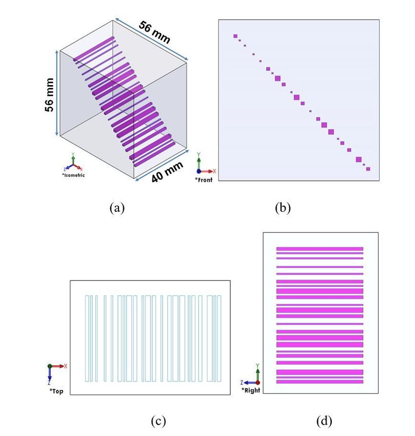
axis from default), the embedded column of surface features is printed with the support material in the
pattern of correct barcode design, and under all other 90° rotation, the model is printed as one solid part.
But this phenomenon may or may not occur under other 3D printing techniques and slicing algorithms. In
summary, by introducing four surfaces (in the shape of rectangular tube) with determined dimensions, a
column of support materials can be printed without any dependence on the slicing orientation. Authentic
parts will be printed by authorized users where support materials are deposited showing the barcode
pattern for tracking and authentication process.

A micro-CT scanning and reconstruction by the Micro-CT system is performed on the FDM 3D printed
modified barcode part as in Fig. 8(a) to validate previous discussion on the reading techniques. The
printed prism, Fig. 8(b), is subjected to micro-CT scan and then cut to physically verify the presence of the
code Fig. 8(c). When exposed to x-ray radiation as in Fig. 8(c), color indication shows the barcode stripes
as printed with a different material than the prism model material. This can also quickly help in validating
different printing results for the modified barcode model with security features under different
orientations. Further, a 3D model can be reconstructed from the computed tomography scanned cross-
section images. This step is necessary because the scanning orientation might not be sufficient to
visualize the barcode pattern based on the assumption that this kind of tracking code can be embedded
with 360° degree of freedom. The reconstructed model can be viewed at any angle and any cross-section
to visualize the barcode pattern as in Fig. 8(c), which shows relatively good barcode pattern and contrast.
With improved printer capability and resolution, dimensional accuracy can be increased, and the tracking
code can be read faster.

2.2.2 Obfuscating multi-layer barcode
By combining the findings described earlier in the sections on multi-layer barcode and obfuscating one-
layer bar code, the multi-layer barcode model as shown in Fig. 5 is enhanced with obfuscation security
feature so that only under certain conditions will the correct barcode be printed, and only a certain
viewing orientation can read the code correctly. The “Extruded Surface” function is performed on the
barcode instead of “Extruded Cut” function. The “Extruded Surface” barcode is 30 mm in length with
square sides that are either 0.6 × 0.6 mm2, 1.2 × 1.2 mm2, or 1.8 × 1.8 mm2, all embedded inside a cuboid
enclosure that is 56 × 40 × 56 mm3 in length × width × height as shown in Fig. 9. The STL model is
exported in coarse STL resolution, which is then imported into the slicer CatalystEX and sliced under
different orientations as shown in Fig. 10. Only under the 90° rotation about x-axis will the barcode be
printed correctly while other orientations cannot print the barcode at all. The STL model is then scaled
down (scale factor 0.4) to a smaller size compatible for micro-CT imaging and sliced after rotations (x-
90° and z-90°) as in Fig. 10(b) and (d) in CatalystEX (Stratasys, USA), and then sent the Stratasys
Dimension Elite FDM 3D printer for 3D printing in ABS plus-P430 (Stratasys, USA) filament material. The
two 3D printed cuboids have a dimension of 22.4 × 16 × 22.4 mm3 in length × width × height. The cuboid
part that is sliced under 90° rotation about x-axis is subjected to micro-CT scan and reconstructed in
NRecon Reconstruction Software to generate a 3D model of the scanned part. The reconstructed 3D
model is opened in SolidWorks 2018 and displayed from side and isometric views as in Fig. 11 to

                                                  Page 8/22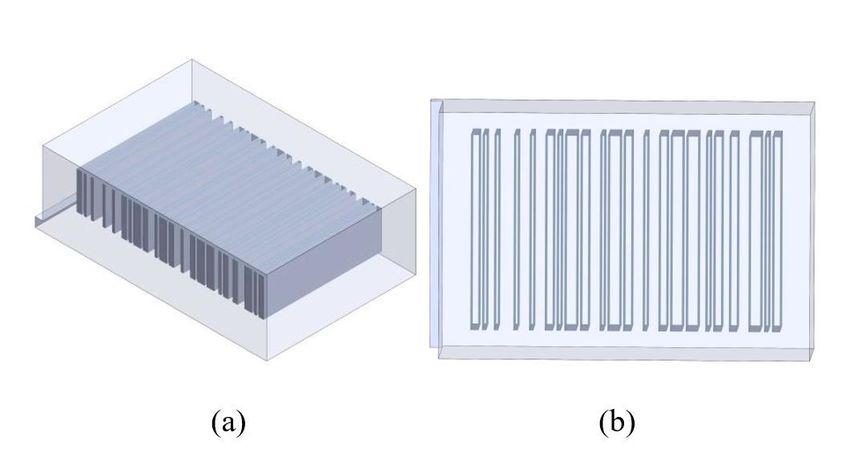
validate that the x-90° rotation slicing orientation can properly generate the embedded barcode inside the
3D printed cuboid.

2.3 Reading techniques
The tracking codes embedded inside the solid model benefit from the freeform solid modelling stage of
AM. In previous examples, we have developed CAD models with embedded tracking code and additively
manufactured 3D objects from these CAD models in a transparent photosensitive polymer material to
facilitate visualization and code pattern validation. However, such a scheme can be developed into any
3D solid model and produced with any materials, without the necessity of being transparent. Under the
scenario of an opaque or translucent appearance model, direct code reading might not be feasible so an
external facility for internal structure visualization needs to be employed. Examples of such non-
destructive reading techniques include ultrasonic imaging and x-ray computed tomography (CT). Here we
demonstrate the feasibility of using a micro-CT machine to acquire internal information of a 3D printed
product with embedded tracking code. During the acquisition, a series of cross-sectional slices will be
generated for the object and used for 3D model reconstruction. Once the internal pattern is reconstructed
using the CT-scan machine, an efficient image processing scheme can be adopted to validate product
authenticity.

From the CAD models and printed objects, it can be observed that currently, AM technologies are capable
of manufacturing tracking codes with similar geometries at high resolution and miniaturized size.
Therefore, in the processing of this reconstructed image, it is promising to apply pre-determined geometry
such as rectangular or squares so as to discriminate signal noises and only acquire the useful
information for image analysis and code authentication. With this, our scheme of a robust and highly
efficient authentication process can be realized and compatible with a broad selection of products.

3. Conclusions
The process of designing, printing, and reading an embedded tracking code is successfully demonstrated
in this article. The 1D barcode example is used for illustration, but more complex design or a multi-layered
code can also be implemented following the similar protocol. Compared to the conventional security
labels that are highly subjected to removal-reapplication attacks, our scheme of embedding “security
labels” inside the product can reduce the risk of security breach. Combined with the additional
obfuscation design, the embedded feature complexity and security is increased to further distinguish the
genuine product from counterfeits. Unauthorized users without access to the key process parameters will
eventually produce counterfeits without the embedded security feature that will fail the authentication
process.

Declarations
FUNDING/ACKNOWLEDGMENTS

                                                 Page 9/22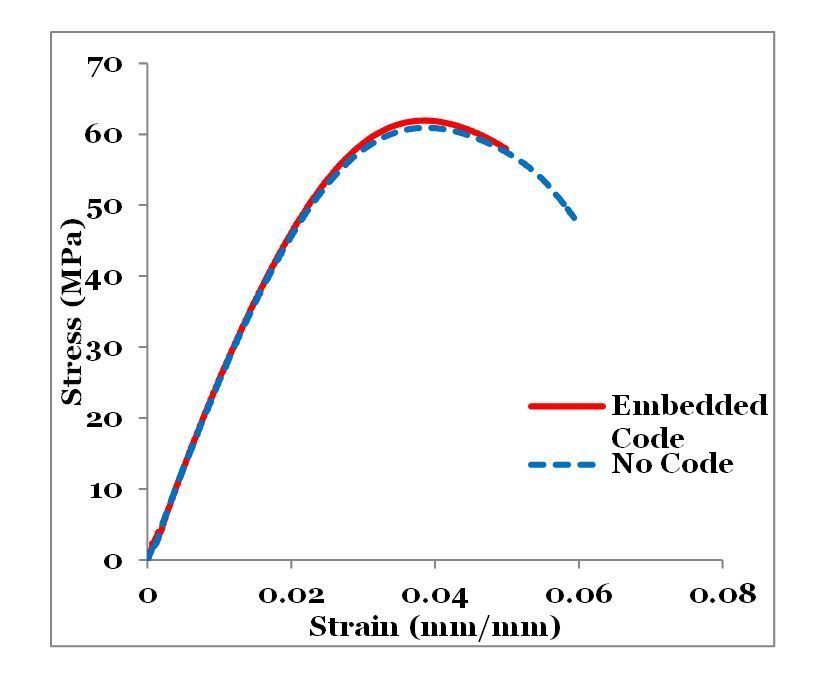
This work is supported by the National Science Foundation grant DGE-1931724 from the Secure and
Trustworthy Cyberspace program. Authors thank NYU Tandon Makerspace for the facilities and support
provided for the experimental work. The views presented in this article are those of the authors, not of the
funding agency.

Conflicts of interest/Competing interests:

The authors have no conflicts of interest to declare that are relevant to the content of this article.

Availability of data and material:

Data can be provided if requested.

Code availability:

Not applicable.

Ethics approval:

This article does not contain any studies with human participants or animals performed by any of the
authors.

Consent to participate:

There are no human participants that are included in the study.

Consent for publication:

The authors have not included any data taken from other individuals.

References
  1. Abdulhameed O, Al-Ahmari A, Ameen W, Mian SH (2019) Additive manufacturing: Challenges, trends,
     and applications. Advances in Mechanical Engineering 11(2):1687814018822880
  2. Mohd Yusuf S, Cutler S, Gao N (2019) Review: The Impact of Metal Additive Manufacturing on the
     Aerospace Industry. Metals 9(12):1286
  3. Longhitano GA, Nunes GB, Candido G, da Silva JVL (2021) The role of 3D printing during COVID-19
    pandemic: a review. Progress in Additive Manufacturing 6(1):19–37
  4. Zeltmann SE, Gupta N, Tsoutsos NG, Maniatakos M, Rajendran J, Karri R (2016) Manufacturing and
     Security Challenges in 3D Printing. JOM 68(7):1872–1881
  5. Yampolskiy M, Andel T, McDonald J, Glisson W, Yasinsac A, Intellectual Property Protection in
     Additive Layer Manufacturing: Requirements for Secure Outsourcing (2014) 1–9

                                                   Page 10/22
6. Padmanabhan A, Zhang J (2018) Cybersecurity risks and mitigation strategies in additive
manufacturing. Progress in Additive Manufacturing 3(1):87–93
7. Sengupta S, Kaulgud V, Sharma VS. Cloud computing security–trends and research directions. in
2011 IEEE World Congress on Services. 2011
8. Mahesh P, Tiwari A, Jin C, Kumar PR, Reddy ALN, Bukkapatanam STS, Gupta N, Karri R, A Survey of
Cybersecurity of Digital Manufacturing. Proceedings of the IEEE, 2020, 1–22
9. Yampolskiy M, Skjellum A, Kretzschmar M, Overfelt RA, Sloan KR, Yasinsac A (2016) Using 3D
printers as weapons. Int J Crit Infrastruct Prot 14(Supplement C):58–71
10. Kurfess T, Cass WJ (2014) Rethinking Additive Manufacturing and Intellectual Property Protection.
Research-Technology Management 57(5):35–42
11. Rengier F, Mehndiratta A, von Tengg-Kobligk H, Zechmann CM, Unterhinninghofen R, Kauczor H-U,
Giesel FL, 3D printing based on imaging data: review of medical applications. International Journal
of Computer Assisted Radiology and Surgery, 2010, 5(4), 335–341
12. Egan PF, Bauer I, Shea K, Ferguson SJ (2019) Mechanics of Three-Dimensional Printed Lattices for
Biomedical Devices. J Mech Des 141(3):031703
13. Bridges SM, Keiser K, Sissom N, Graves SJ Cyber Security for Additive Manufacturing. in Proceedings
of the 10th Annual Cyber and Information Security Research Conference. April 7–9, 2015 Oak Ridge,
TN, USA: ACM
14. Sturm LD, Williams CB, Camelio JA, White J, Parker R, Cyber-physical vulnerabilities in additive
manufacturing systems: A case study attack on the.STL file with human subjects. Journal of
Manufacturing Systems, 2017, 44, Part 1, 154–164
15. Gupta N, Chen F, Shahin K, Design features to address security challenges in additive manufacturing,
Manufacturing Techniques for Materials: Engineering and Engineered, T.S. Srivatsan, T.S. Sudarshan,
and K. Manigandan, Editors. 2018, CRC Press: Taylor & Francis Group
16. Bayens C, Le T, Garcia L, Beyah R, Javanmard M, Zonouz S See no evil, hear no evil, feel no evil, print
no evil? Malicious fill patterns detection in additive manufacturing. in 26th {USENIX} Security
Symposium ({USENIX} Security 17) (2017) Vancouver, BC: {USENIX} Association
17. Chaduvula SC, Dachowicz A, Atallah MJ, Panchal JH (2018) Security in Cyber-Enabled Design and
Manufacturing: A Survey. J Comput Inf Sci Eng 18(4):040802
18. Gupta N (2020) Embedded security elements for digital models used in additive manufacturing.
Google Patents
19. Lehtonen M, Oertel N, Vogt H Features, identity, tracing, and cryptography in product authentication.
in (2007) IEEE International Technology Management Conference (ICE). 2007. Sophia-Antipolis,
France: IEEE
20. Shah RY, Prajapati PN, Agrawal Y (2010) Anticounterfeit packaging technologies. J Adv Pharm Tech
Res 1(4):368
Page 11/2221. Li L (2013) Technology designed to combat fakes in the global supply chain. Bus Horiz 56(2):167–
177
22. Craver S, Memon N, Yeo B, Yeung MM (1998) Resolving rightful ownerships with invisible
watermarking techniques: limitations, attacks, and implications. IEEE J Sel Areas Commun
16(4):573–586
23. Juels A, Pappu R Squealing Euros: Privacy Protection in RFID-Enabled Banknotes. in International
Conference on Financial Cryptography (2003) Berlin, Heidelberg: Springer Berlin Heidelberg
24. Qian J-P, Yang X-T, Wu X-M, Zhao L, Fan B-L, Xing B (2012) A traceability system incorporating 2D
barcode and RFID technology for wheat flour mills. Comput Electron Agric 89:76–85
25. Mun IK, Kantrowitz AB, Carmel PW, Mason KP, Engels DW Active RFID System Augmented With 2D
Barcode for Asset Management in a Hospital Setting. in (2007) IEEE International Conference on
RFID. 2007. Grapevine, TX, USA: IEEE
26. Song B, Mitchell CJ. RFID authentication protocol for low-cost tags. in Proceedings of the first ACM
conference on Wireless network security (2008) Alexandria, VA, USA: ACM
27. Lehtonen MO, Michahelles F, Fleisch E (2007) Trust and security in RFID-based product
authentication systems. IEEE Syst J 1(2):129–144
28. Chen F, Mac G, Gupta N (2017) Security features embedded in computer aided design (CAD) solid
models for additive manufacturing. Materials Design 128:182–194
29. Chen F, Yu JH, Gupta N, Obfuscation of embedded codes in additive manufactured components for
product authentication. Advanced Engineering Materials, 2019
30. Gupta N, Chen F, Tsoutsos NG, Maniatakos M ObfusCADe: Obfuscating additive manufacturing CAD
models against counterfeiting: Invited. in Proceedings of the 54th Annual Design Automation
Conference (2017) 2017. Austin, TX, USA: ACM
31. Chen F, Luo Y, Tsoutsos NG, Maniatakos M, Shahin K, Gupta N (2018) Embedding tracking codes in
additive manufactured parts for product authentication. Adv Eng Mater.
doi:10.1002/adem.201800495
32. Peternikolow. 1D, 2D & 3D Barcodes (2012) [cited 2021 June 2]; Available from:
http://www.mobiliodevelopment.com/1d-2d-3d-barcodes/
33. Peternikolow. Code39 and Code128 in a nutshell (2012) [cited 2021 June 2]; Available from:
http://www.mobiliodevelopment.com/code39-and-code128-usage/
Figures
Page 12/22Figure 1
A 1D code 128 is generated (a) for the string character “CMML” using an online barcode generator
https://barcode.tec-it.com/en, and (b) convert into a CAD model using “Extruded Cut” function (code
dimensions 474×300×100mm3, enclosure cuboid dimensions 630×380×200mm3).
Page 13/22Figure 2
3D printed resin bar code 1-layer part with measured prism dimensions (a) 30 × 18 × 10mm3, and (b) 10
× 6 × 3mm3 where code dimensions should be (a) 22.57 × 14.21 × 5mm3 and (b) 7.52 × 4.74 × 1.5mm3,
respectively.
Page 14/22Figure 3
(a) CAD model of a standard tensile bar (ASTM D638 type I) with embedded barcode 128 (representing
“CMML”), barcode is in dimensions 7 × 4.43 × 0.5 mm3, and (b) 3D printed tensile bar with embedded
barcode in VeroClear photopolymer, where the zoomed in inlet shows the front view and barcode of
thickness around 0.5 mm.
Page 15/22Figure 4
Stress-strain diagram for standard tensile bars (ASTM D638 type I) with and without embedded barcode
(1-layer).
Page 16/22Figure 5
CAD model of a cuboid with barcode that are “Extruded Cut” and embedded at 22 different layers is 3D
printed with VeroMagenta (barcode volume) and VeroClear (outer enclosure) photopolymers.
Figure 6
The obfuscating embedded barcode CAD model of a cuboid with barcode that are “Extruded Surfaces”
based on barcode pattern shown in (a) isometric view and (b) front view showing that extruded surfaces
are introduced based on the shape of barcode stripes.
Page 17/22Figure 7
The modified barcode model is imported into CatalystEX and sliced under default orientation and under
manually adjusted orientation (90° rotation about x-axis) shown in isometric and top views. The
manually adjusted orientation (90° rotation about x-axis) shows partial barcode pattern toolpath (prism
dimensions are 16.44×10.96×5.48 mm3, minimum barcode stripe width is 0.178 mm with a scale factor
of 1.37 applied).
Page 18/22Figure 8
(a) The modified barcode model is imported into CatalystEX and sliced under manually adjusted
orientation (90° rotations about x-axis) shown in isometric view and top view (prism dimensions are 49.2
× 32.8 × 16.4 mm3, minimum barcode stripe width is 0.534 mm with a scale factor of 4.1 applied). (b)
The 3D printed barcode part (32.88 × 21.92 × 10.96 mm3), which is subjected to (c) x-ray radiation
exposure (top), and then CT reconstructed to show in higher image contrast and FDM 3D printed (bottom)
with prism dimensions 32.88 × 21.92 × 10.96 mm3 (scale factor of 2.74) and 49.2 × 32.8 × 16.4 mm3
(scale factor of 4.1) as presented when cut in half.
Page 19/22Figure 9
CAD model of a cuboid with barcode that are “Extruded Surfaces” and embedded at 22 different layers
(a) isometric, (b) front, (c) top, and (d) right side views.
Page 20/22Figure 10
CAD model of a cuboid with barcode that are “Extruded Surfaces” and embedded at 22 different layers
imported in CatalystEX Slicer software and slices under (a) default orientation, (b) rotate 90° about x-axis,
(c) rotate 90° about y-axis, and (d) rotate 90° about z-axis. Only case (b) shows the embedded barcode.
Figure 11
(a) A 3D printed cuboid with embedded barcode distributed at 22 different layers is subjected to micro-CT
scan (Bruker SkyScan 1172, Micro Photonics Inc, USA) and reconstructed in NRecon Reconstruction
Page 21/22Software (Micro Photonics Inc, USA) to generate a 3D model of the scanned part, which is opened in
SolidWorks 2018 and displayed from (b1) side and (b2) isometric views. The slicing orientation is 90°
rotation about x-axis for the printed part to properly generate the embedded barcode.
Supplementary Files
This is a list of supplementary files associated with this preprint. Click to download.
SpecificRemarks.docx
Page 22/22You can also read