Kinematical Asymmetry in Dwarf Irregular Galaxy WLM and a Perturbed Halo Potential
←
→
Page content transcription
If your browser does not render page correctly, please read the page content below
Astronomy & Astrophysics manuscript no. Paper ©ESO 2021
July 8, 2021
Kinematical Asymmetry in Dwarf Irregular Galaxy WLM and a
Perturbed Halo Potential
M. Khademi1, 2,? , Y. Yang1,?? , F. Hammer1,??? , and S. Nasiri2,????
1
GEPI, Observatoire de Paris, Universite PSL, CNRS, Place Jules Janssen 92195, Meudon, France
2
Department of Physics, Shahid Beheshti University, G.C., Daneshjou Boulevard, District 1, 19839 Tehran, Iran
July 8, 2021
arXiv:2107.02928v1 [astro-ph.GA] 6 Jul 2021
ABSTRACT
WLM is a dwarf irregular that is seen almost edge−on, which has prompted many kinematical studies to investigate its rotation
curve and its dark matter content. In this paper we investigate the origin of the strong asymmetry of the rotation curve, which shows a
significant discrepancy between the approaching and the receding side. We first examine whether an m = 1 perturbation (lopsidedness)
in the halo potential could be a mechanism creating such kinematical asymmetry. To do so, we fit a theoretical rotational velocity
associated with an m = 1 perturbation in the halo potential model to the observed data via a χ−squared minimization method. We
show that a lopsided halo potential model can explain the asymmetry in the kinematic data reasonably well. We then verify that the
kinematical classification of WLM shows that its velocity field is significantly perturbed, because of both its asymmetrical rotation
curve, and also because of its peculiar velocity dispersion map. Also based on kinemetry analysis, it is possible that WLM lies in the
transition region, in which disk and merger coexist. In conclusion, it appears that the rotation curve of WLM diverges significantly
from that of an ideal rotating disk, which may significantly affect investigations of its dark matter content.
Key words. Galaxies: kinematics and dynamics - galaxies: dark matter halo - galaxies: structure - galaxies: dwarf - galaxies: Local
Group
1. Introduction are elongated in one half of these galaxies (Edmondson 1961).
Such an asymmetry first time, detected in the spatial extent of
It is accepted that disk galaxies have massive dark matter halos the atomic hydrogen gas in the outer regions in two halves of
but little is known about the shape of such halos in the galaxies some galaxies, and also in distribution of light (Baldwin et al.
and their content. Dark halos were modeled as being spherical 1980). A galaxy showing a global non-axisymmetric spatial dis-
until Binney (1978) suggested that the natural shape of dark ha- tribution of type m = 1 perturbation in the potential or a cos(φ)
los is triaxial. Triaxial dark matter halos come to pass naturally distribution where φ is the azimuthal angle in the plane of the
in cosmological simulations of structure formation in the uni- disk, is a lopsided galaxy (Jog 1997). The asymmetric distribu-
verse. These simulations also illustrate that there may be a uni- tion of HI gas ( Morphological lopsidedness in HI gas ) in spiral
versal density profile for dark matter halos (Navarro et al. 1996; galaxies such as M101 was reported in the early HI observa-
Cole & Lacey 1996), but the accurate distribution of halo shapes tions (Beale & Davies 1969). These kinds of galaxies which are
is still unclear. Observed distribution of the shapes of dark mat- more extended on one side than the other were named lopsided
ter halos can be a constraint on the scenarios of galaxy formation galaxies.
and evolution. Investigating the shapes of dark halos can be done
Morphological lopsidedness was confirmed in a Fourier-
in two parts: measuring the the ratio c/a , i.e., flattening perpen-
analysis study of a large sample of 149 galaxies, about one third
dicular to the plane of the disk, and measuring the the intermedi-
of galaxies of this sample showed asymmetry in the amplitude of
ate to major axis ratio b/a , i.e., the elongation of the potential,
the m = 1 Fourier component (Bournaud et al. 2005). Thus, mor-
which is of type m = 2 perturbation in the potential and useful
phological lopsidedness in the disk is a general phenomenon. So,
to measure the elongation of orbits. The effects of a global elon-
it is important to investigate the origin and dynamics of the lop-
gation of the dark matter halo are similar to an m = 2 spiral arm
sided distribution in the galaxies. The lopsided (perturbed) distri-
(Schoenmakers et al. 1997).
bution in the atomic hydrogen gas has been mapped morpholog-
Asymmetries in the distribution of light and neutral hydro-
ically (Haynes et al. 1998), and also mapped kinematically for a
gen gas HI are often observed in spiral galaxies and it has been
few galaxies (Schoenmakers et al. 1997; Swaters et al. 1999) and
known for a long time that the light distribution and therefore
by global velocity profiles for a larger sample (Richter & Sancisi
the mass distribution in disks of spiral galaxies is not closely
1994). Also such asymmetry has been found in dwarf galaxies
axisymmetric, for example isophotes of M101 and NGC1637
(Swaters et al. 2002), and in the star forming regions in the ir-
?
ma_khademi@sbu.ac.ir regular galaxies (Heller et al. 2000). The asymmetry may affect
??
yanbin.yang@obspm.fr all scales in a galaxy, but the large-scale lopsidedness is more ob-
???
Francois.Hammer@obspm.fr vious. This kind of m = 1 perturbation is expected to have a sig-
????
nasiri@iasbs.ac.ir nificant impact on the dynamics of the galaxies, their evolution,
Article number, page 1 of 12
A&A proofs: manuscript no. Paper

the star formation in them and also may play an important role         observational HI data cube is asymmetric too. The spider-like
in the growth of the central black hole and on the nuclear fueling     shape of iso-velocity contours are curved more strongly on the
of the active galactic nucleus (AGN) in a galaxy (Jog 1999; Jog        approaching side and take on the characteristic shape of differ-
& Combes 2009). A perturbation in the gravitational potential          ential rotation, while the iso-velocity contours on the receding
of a dark matter halo can make a galaxy asymmetric and create          side remain more or less straight and mostly parallel to the mi-
asymmetry in the gas surface density profile (Jog 1997, 2000).         nor axis, which is consistent with regular solid-body rotation.
Also, a symmetric dark matter halo can produce an asymmet-             Dwarf irregular galaxies usually have a slowly-rising rotation
ric galaxy if the disc orbits off centre with respect to the overall   curve close to a solid body and there is lack of differential ro-
potential (Levine & Sparke 1998).                                      tation in dwarf irregular galaxies (Kepley et al. 2007; Lelli, F.
     A new area that is beginning to be investigated is the asym-      et al. 2012). Also the global HI emission profile of WLM shows
metry at the centers of mergers of galaxies. A systematic re-          a strong asymmetry (Kepley et al. 2007; Ianjamasimanana et al.
search was done recently by (Jog & Maybhate 2006), in order to         2020). Global HI line profiles are influenced by both of the kine-
understand the lopsidedness of the intensity and luminosity dis-       matics and the HI distribution. The shape of the global line pro-
tribution and hence the mass asymmetry within their central few        file has been determined by both the kinematics and the density
kpc regions of mergers. Recently Ghosh et al. (2021) have done         distribution of the gas. Galaxies with such asymmetric global
a simulation study of lopsided asymmetry generated in a minor          line profiles often have rotation curves that are steeper on one
merger to investigate the dynamical effect of the minor merger of      side of the galaxy than on the other side (Swaters et al. 1999).
galaxies on the excitation of lopsidedness. The lopsided modes              This paper is organized as follows: In Sec. 2, we will de-
and the central asymmetry that is merger-driven, can play an im-       rive the velocity fields map from two different kinematic models
portant role in the dynamical evolution of the central regions,        for this galaxy, solid body rotation and differential rotation, if
especially on the star formation in it and on the nuclear fueling      this galaxy orbits in the potential of an axisymmetric dark halo.
by outward transporting of the angular momentum. Therefore             in Sec. 3, we will review the dynamics of orbits in a lopsided
these process can be important in the hierarchical evolution of        halo potential (non−axisymetric potential) and extract the rota-
galaxies (Jog & Combes 2009).                                          tion curve of WLM by fitting a theoretical rotational velocity as-
     The kinematical lopsidedness or a cos(φ) asymmetry is often       sociated with an m = 1 perturbation in the halo potential model
also observed in the kinematics of the galaxies and therefore in       to the observed data for both of receding and approaching sides.
the velocity fields (Schoenmakers et al. 1997) and in the rota-        We will also generate velocity field map and surface density map
tion curves on two halves of a galactic disk (Swaters et al. 1999;     for HI gas disk and stellar disk from this model associated with
Sofue & Rubin 2001). A galaxy showing a spatial asymmetry be-          an m = 1 perturbation in the halo potential (a lopsided halo po-
tween two sides of the galaxy would naturally show kinematical         tential model). in Sec. 4, based on kinematic asymmetries, for
asymmetry except in the cases of face−on galaxies. A face−on           investigating weather merger could have created such a lopsid-
galaxy can show morphological asymmetry but can not show               edness in the halo potential, we will determine the amplitude of
kinematical asymmetry (Jog 2000, 2002; Jog & Combes 2009).             velocity asymmetry and the strength of deviation of the velocity
But in the past, several papers have made a distinction between        field of a perturbed rotation model (an m = 1 perturbation in the
the spatial or morphological lopsidedness and kinematical lop-         potential) from that of an ideal rotating disk case by obtaining
sidedness (Swaters et al. 1999; Noordermeer et al. 2001) and           the relative level of deviation of the velocity field from that of an
have even claimed (Lovelace et al. 1999) that the velocity asym-       ideal rotating disks case. Also based on σ - centering, we will
metry is not always correlated with the morphological asymme-          classify this galaxy as a galaxy with perturbed rotations. Finally
try. Dwarf irregulars are the most common type of galaxies in the      in Sec. 5, we will present concluding remarks.
local universe (see for example Dale et al. (2009) ). These galax-
ies with extended HI disk distributions allow measurement of
rotation curves and hence investigate dark matter halo properties      2. Modeling the Velocity Fields of the Rotating
and its shape to large radial distances, beyond the optical disk.         Disks and Different types of galactic rotation
These kind of galaxies contain a huge reservoir of dark matter
                                                                       In a rotating disk, the bulk motions can be projected as ellipses
halo that dominates over most of disk (Ghosh & Jog 2018).
                                                                       on the sky. Orientation of such ellipses depends on the disk incli-
     WLM is a near edge-on gas rich dwarf irregular galaxy in the      nation and kinematic position−angle. The observed line-of-sight
Local Group. This galaxy is rotationally supported and clearly         radial velocity vlos extracted along such ellipses can be described
rotating and isolated from massive galaxies (Kepley et al. 2007).      as
It is worth noting that WLM in the local group, as well as most
of those dwarf irregular galaxies identified as kinematically lop-     vlos (R, ψ) =vc (R, ψ) sin(i) cos(ψ) + vr (R, ψ) sin(i) sin(ψ)+
sided, is an isolated system and does not show any signs of
strong tidal interaction and there isn’t any clear evidence for on-                 vz (R, ψ) cos(i) + v sys                             (1)
going accretion of satellite galaxies. The dwarf irregular galaxy      Here v sys is the systemic velocity of the galaxy that corresponds
WLM has interesting dynamics that has recently been studied            to the galaxy red-shift, vc (R) is the circular (rotational) velocity
by a number of groups. WLM’s rotation curve is asymmetric,             in the azimuthal ψ direction, vr is the radial velocity in the disk
the rotation curves for the approaching and the receding halves        plane, and vz traces vertical motions. The azimuthal angle ψ is
of WLM are not symmetric and they are distinctly different. In         measured from the projected major axis in the plane of galaxy,
this galaxy, the rotation curve of receding side rises much more       R is the radius of a circular ring in that same plane (or the semi-
slowly than it for the approaching side, the velocity gradient for     major axis length of the ellipse once projected on sky), and i is
the approaching side is steeper than for it for the receding side      the inclination of the disk (i = 0 for a disk seen face-on) (Ham-
in the outer region for this galaxy. The rotation curve of the         mer et al. 2017).
approaching side rises that flattens at a certain radius, whereas
the rotation curve for the receding side continues to rise (Ke-
pley et al. 2007). WLM’s velocity field map obtained from an           2.1. Velocity fields of axisymmetric disk galaxies

Article number, page 2 of 12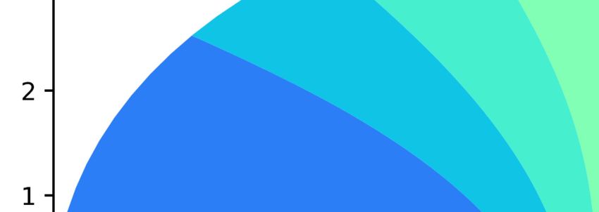
M. Khademi et al.: Kinematical Asymmetry in Dwarf Irregular Galaxy WLM and a Perturbed Halo Potential

( 2-D model: rotating disk)                                               representation of a rising-to-flat rotation.
                                                                          By programming in Python, we generated the velocity field
If the cold HI gas in a disk galaxy orbits in the potential of an         maps from two different kinematic models for this galaxy, solid
axisymmetric dark halo (a static, spherically symmetric gravi-            body rotation (slowly rising rotation curve) and differential
tational potential field), the resulting density field and velocity       rotation (steeply rising-to-flat rotation curve) in Figures 1. This
field are axisymmetric as well. This means that the velocity field        figures show contours of constant velocities and the major
will only show pure circular rotation and the predominant mo-             axis of these velocity field map is horizontal for each of these
tion of gas in a spiral galaxy is rotation and the observed velocity      models.
fields of disk galaxies generally can be fitted perfectly by circular       In Table 1, column (1) gives position angle of major axis,
motion. Assuming that, at radius R, a gas cloud follows a near-           measured in degree, column (2) gives Median inclination
circular path with speed vc (R) . All we can detect of this motion        angle of galaxy in unit of degree, and column (3) gives he-
is the line- of- sight radial velocity vlos toward or away from           liocentric distance. column (4) gives systematic velocity of
us; its value at the galaxy’s centre, v sys , is the systemic velocity.   galaxy, column (5) gives ellipticity,  = 1 − b/a, where a
For an ideal rotating disk (a disk with pure rotational motion),          and and b are the semi-major axis length and semi-minor
the observed velocity fields are fitted with circular velocity and        axis length respectively. The ratio of the semi-major axis a
with no radial or out of plane motions (noncircular motions). In          and the semi-minor axis b quantifies how far the isophote
such an ideal rotating thin disk, the bulk motions draw circular          (contour of constant surface brightness) differs from a circle.
orbits in the plane of galaxy, projected on-sky as ellipses (Kra-         column (6) gives half-light radius in parsec and column (7)
jnović et al. 2006). For a given projected elliptical HI ring, the       gives radius of extension of HI gas in parsec. column (8) gives
projected velocity along the line-of-sight (radial velocity) is:          absolute visual magnitude, column (9) gives conversion factor
vlos (R, ψ) = vc (R) sin(i) cos(ψ) + v sys                         (2)    from arcsec to pc and column (10) gives mean stellar metallicity.

where v sys is the systemic velocity of the galaxy, vc (R) is the
circular (rotational) velocity of the gas at radius R, ψ is the
azimuthal angle of the rings in the plane of the galaxy, gives a          3. DYNAMICS OF ORBITS IN A LOPSIDED
star’s position in its orbit and i is the disk inclination (i = 0 for        POTENTIAL (DESCRIPTION OF A PERTURBED
a disk seen face-on). The observed line-of-sight radial velocity             VELOCITY FIELD Model)
vlos , toward or away from an observer, are usually measured
using the Doppler shift of emission line or absorption line in the        A simple rotating disk can not reproduce the asymmetries that
spectra of HI gas or stars.                                               are seen in the observed velocity field and in the rotation curve of
                                                                          WLM. The asymmetry in the rotation curve between approach-
                                                                          ing and receding sides of the galaxy, rising more steeply on one
2.2. Solid-body rotation
                                                                          side than on the other side, is a signature of the kinematical lop-
                                                                          sidedness in the galaxy (Swaters et al. 1999). We are going to
A homogeneous density distribution produces solid-body rota-              investigate whether the kinematical asymmetry in WLM may
tion with Ω = vc (R)/R = constant. If we plug this into equation          be related to lopsidedness in the halo potential and kinematic
(2), we get                                                               lopsidedness can be caused by a perturbed halo potential and
                                                                          whether this galaxy is lopsided in its kinematics.
vlos = ΩR sin(i) cos(ψ) + v sys                                    (3)    Assuming that the galaxy is a rotating disk and then investigating
                                                                          the model deviations to verify the accuracy of this assumption is
Because, x = R cos(ψ), this becomes simply
                                                                          a simple way to study kinematics of a galaxy (Hammer et al.
vlos = Ωx sin(i) + v sys                                           (4)    2017).
                                                                          Here, we will analyse the case of the small deviations from ax-
therefore the velocity does not depend on y and contours of con-          isymmetry of the potential V of a filled gaseous disk, which can
stant velocity will be parallel to the y axis. Vertical contours of       be written as a sum of harmonic components.
the constant velocity near the centre of a two-dimensional veloc-         The assumptions that the potential includes a small perturbation
ity field is indicative of the solid-body rotation.                       and that the gas moves on the stable closed orbits allow us to use
                                                                          epicycle theory to analyse the velocity fields that are caused by
                                                                          such a perturbed potential.
2.3. Differential Rotation
                                                                          The orbits are solved via first-order epicyclic theory. The treat-
A simple model for differential rotation is cored logarithmic po-         ment of orbits in the weak non-axisymmetric potentials is closely
tential which can produce a rising rotation curve that flattens at        related to the epicycle theory of nearly circular orbits in an ax-
a certain radius (rising-to-flat rotation curve).                         isymmetric potential.
                                                                          To assist in the description of the non-axisymmetric features of
           1 2                                                            the motion of the gas, the velocity fields have been decomposed
V0 (R) =    v ln[R2c + R2 ]                                        (5)
           2 0                                                            into harmonic components along individual elliptical rings fol-
which has                                                                 lowing the approach of SFdZ method presented by Schoenmak-
                                                                          ers et al. (1997). For studying the dynamics of particles (HIgas)
           v0 R                                                           in a galactic disk perturbed by a lopsided dark matter halo poten-
vc (R) = p                                                         (6)
          R2 + R2c                                                        tial, we will use the equations of motion in this perturbed poten-
                                                                          tial for the possible closed orbits. In this way the observed veloc-
where Rc and v0 are constants that v0 is circular velocity at large       ity field can be directly related to the potential of disk galaxies.
R. At R  Rc , this corresponds to solid-body rotation and at             Here, we will analyze the case of a small perturbation in the
R  Rc the rotation curve is flat; this model is therefore a good         potential V, which can be written as a sum of harmonic compo-
                                                                                                                  Article number, page 3 of 12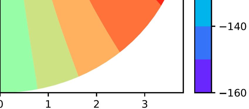
A&A proofs: manuscript no. Paper

                                                         Velocity (km/s)                                                               Velocity (km/s)
                                                                     60                                                                            60
    3                                                                  75          3                                                              75
    2                                                                  90          2                                                              90
    1                                                                  105         1                                                              105
    0                                                                  120         0                                                              120
    1                                                                  135         1                                                              135
    2                                                                  150         2                                                              150
    3                                                                  165         3                                                              165
                                                                       180                                                                        180
                    2              0           2                                                    2            0               2
                                        (a)                                                                          (b)

Fig. 1. Pure Circular Rotations: (a) Velocity Field Map for Solid Body Rotation Model, obtained from the model-cube. iso-velocity contours are
mostly parallel to the minor axis, indicating a solid-body rotation. (b) Velocity Field Map for Differentially-Rotating Disk-Model (rising-to-flat),
obtained from the model-cube. Iso-velocity contours of the velocity field map display strong curvatures indicating of differential rotation.

Table 1. Photometric and structural parameters of WLM.

        (1)                       (2)              (3)           (4)             (5)          (6)          (7)             (8)       (9)   (10)
                                                                                    b
 position angle Median inclination Distance V sys (km/s)                       =1−
                                                                              Rh (pc) Rmax (pc) Mv (mag)          fc    Fe /H
                                                                                    a
   (degree)         angle (degree)     (kpc)
        4a                75b           933a      −122 ± 4 c        0.65a      2111a    2304 b       -14.2a      4.8d -1.27a
   References: (a) (McConnachie 2012), (b) (Kepley et al. 2007) , (c) (Ianjamasimanana et al. 2020) and (d) (Iorio et al. 2017)

nents. Schoenmakers et al. (1997) have presented a method for                 One can calculate the amplitude kn of each Fourier harmonic
measuring small deviations from symmetry in the velocity field                order n from the cn and sn coefficients:
of a filled gas disc which arises from small perturbation in the                   q
potential. This method is based on a higher order harmonic ex-                kn = c2n + s2n                                          (9)
pansion of the velocity field of the disc. This expansion has been
made by first fitting a tilted-ring model to the velocity field of            The line-of-sight velocity field in an ideal rotating disk (in pure
the gaseous disk and subsequently expanding the full velocity                 circular rotation) is dominated by the cos(ψ) term. The velocity
field along each ring into its harmonic terms. The epicycle the-              field of a disk which orbits in a non-perturbed potential, shows
ory have been used to derive equations for the harmonic terms in              only pure circular rotation that is given by
a perturbed potential (Schoenmakers et al. 1997).
Harmonic expansion                                                            vlos = vc (R) sin (i) cos (ψ) .                                     (10)
The symmetries in kinematic of galaxies can be measured via the
kinemetry method developed and explained by Krajnović et al.
(2006) and Shapiro et al. (2008).                                             We project the velocity field on the sky. The line-of-sight veloc-
A velocity field map can be divided into a number of elliptical               ity field is given by:
rings and along each elliptical ring, the moment as a function of                        h                                    i
angle is extracted and decomposed into the Fourier series:                    vlos (R) = vR cos(θ − θobs ) − vφ sin(θ − θobs ) sin(i)
                                                                                         h                                      i
                  X                                                               vlos = vR cos(φ − φobs ) − vφ sin(φ − φobs ) sin(i)       (11)
vlos (ψ) = c0 +         cn cos(nψ) + sn sin(nψ)                         (7)
                  n=1                                                         This velocity field is observed from a direction (θobs , i), where
                                                                              the angle i is the inclination of the plane of the disk with respect
where c0 , gives the systemic velocity of each elliptical ring. This          to the observer and R and θ are polar coordinates in the rest frame
yield the velocity profiles to be described by a finite number of             (non-rotating frame) of the galaxy and θobs is is defined as the
harmonic terms as well. So we can express the line-of-sight ve-               angle between the line θ = 0 and the observer (see Figure 2),
locity as                                                                     but φobs is the viewing angle, the angle in the rotating frame that
                        X                                                     corresponds to θobs (the angle between the line φ = 0 and the
vlos (R, ψ) = v sys +         cn cos(nψ) + sn sin(nψ)                   (8)   observer that is zero along the major axis of the orbits).
                        n=1
                                                                               Introduce the variable ψ = θ − θobs + π/2 = φ − φobs + π/2, then:
Article number, page 4 of 12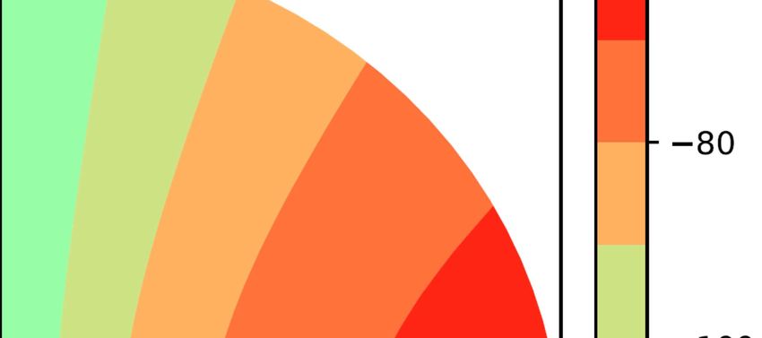
M. Khademi et al.: Kinematical Asymmetry in Dwarf Irregular Galaxy WLM and a Perturbed Halo Potential

                                                                                where v∗ = vc (R) sin i, α = d ln[vc (R)]/d ln(R) and ϕm =
                                                                            φobs − π/2 − φm (R). The explicit computations and derivation of
                                                                            the kinematic asymmetry based on the harmonic expansion have
                                                                            been presented by Schoenmakers et al. (1997) and Schoenmak-
                                                                            ers (1999).
                                                                            From Eq. (16) one can conclude if the potential includes a per-
                                                                            turbation of harmonic number m, the line-of sight velocity field
                                                                            includes m + 1 and m − 1 terms. So, in the case of a harmonic
                                                                            number m = 1 term in the potential (causing morphological lop-
                                                                            sidedness), the line-of-sight velocity field will include an m = 0
                                                                            term and an m = 2 term.

                                                                            3.1. Model Velocity field map, Rotation Curve and surface
                                                                                 density in a lopsided potential
                                                                            In this section we generate velocity field map, rotation curve
                                                                            and surface density map for a perturbed potential to investigate
                                                                            whether such a potential is capable to create asymmetry in kine-
                                                                            matic and distribution of the galaxy.
Fig. 2. Geometry of the projected orbit which is indicated by green el-
lipse and lies in X-Y plane. The orbit is elongated along the Y axis. The
Z−axis is perpendicular to X-Y plane, i.e. the plane of the orbit. The      3.1.1. Effect of m = 1 distortion and making some simplifying
viewing angle θobs and i are the polar coordinate of the line-of sight.            assumptions
The inclination angle i is measured from the Z−axis. The angle θobs is
measured from the line θ = 0. The azimuthal angle ψ is the angle in the     We can map the velocity field in a lopsided potential from the
plane of the orbit and it’s defined to be zero at the line of nodes.        measured harmonic terms. For this aim we make some simplify-
                                                                            ing assumptions:

vlos = vR sin(ψ) sin(i) + vφ cos(ψ) sin(i)                          (12)    1. The m = 1 potential perturbation is dominant over the m = 3
                                                                               term.
The angle ψ is measured along the orbit, this angle is zero at the          2. The pattern speed of the m = 1 perturbation is zero: ω1 = 0.
line of nodes. Sometimes this angle called the azimuthal angle              3. There is no radial dependence  of the phase of perturbation:
                                                                                                  0
and is defined by the orientation of the galaxy on the sky and is              φ1 (R) = const ⇒ φ1 (R) = 0.
independent of the internal coordinate system.
By replacing φ → ψ + φobs − π/2 in the expressions for vR and               So the line-of-sight velocity field can be obtained as follows (The
vφ , expanding the line-of-sight velocity in multiple angles of ψ           explicit computations has been previously derived by Schoen-
and defining:                                                               makers et al. 1997 and Schoenmakers 1999) :
v∗ = vc (R) sin i
                                                                                   X
                                                                    (13)    vlos =     cn cos(nψ) + sn sin(nψ)                              (17)
                                                                                    n
and also assuming to first order φ0 ≈ φ, the line-of-sight veloc-
ity field has the following form (Schoenmakers et al. 1997 and              If the potential includes a perturbation of harmonic number m,
Schoenmakers 1999):                                                         the line-of sight velocity field includes m + 1 and m − 1 terms.
       X
vlos =     cn cos(nψ) + sn sin(nψ)                           (14)           vlos =c1 cos ψ + sm−1 sin(m − 1)ψ + cm−1 cos(m − 1)ψ+
         n                                                                        sm+1 sin(m + 1)ψ + cm+1 cos(m + 1)ψ.                     (18)
vlos =c1 cos ψ + sm−1 sin(m − 1)ψ + cm−1 cos(m − 1)ψ+
      sm+1 sin(m + 1)ψ + cm+1 cos(m + 1)ψ.                          (15)    In the case of a harmonic number m = 1 term in the potential,
                                                                            the line-of-sight velocity field will include an m = 0 term and an
where                                                                       m = 2 term. So for m = 1, we have
  c1 =v∗ ,                                                                  vlos = c1 cos ψ + c0 + s2 sin(2ψ) + c2 cos(2ψ)                 (19)
              1
sm−1   =v∗ (− {[m − (m + 1)ωm + α]a1m + (1 − ωm )a3m } sin(mϕm )            with:
              4
            1                                                                      vc sin i                          0
         + {m(1 − ωm )a4m + [m(1 − ωm ) − 1 + α]a2m } cos(mϕm )),           c0 =               [3V1 (R) + (2 + α)RV1 (R)] cos ϕ1           (20)
            2                                                                    2vc (1 + 2α)
            1                                                                            sin i                  0
sm+1   =v∗ ( {[m − (m − 1)ωm − α]a1m − (1 − ωm )a3m } sin(mϕm )             c2 = −               [V1 (R) − αRV1 (R)] cos ϕ1                (21)
            4                                                                       2vc (1 + 2α)
            1                                                                         sin i
         + {m(1 − ωm )a4m − [m(1 − ωm ) + 1 − α]a2m } cos(mϕm )),           s2 =
                                                                                                              0
                                                                                               [V1 (R) − αRV1 (R)] sin ϕ1                  (22)
            2                                                                    2vc (1 + 2α)
              1                                                             c1 =vc sin(i)
cm+1   =v∗ (− {[m − (m − 1)ωm − α]a1m − (1 − ωm )a3m } cos(mϕm )                                                                           (23)
              4
            1                                                               with i is the !inclination angle of the galaxy and ϕ1 = φobs −π/2 =
         + {m(1 − ωm )a4m − [m(1 − ωm ) + 1 − α]a2m } sin(mϕm )),                      s2
            2                                                               arctan − . φ1 is one of the viewing angles, the angle in the
                                                            (16)                       c2
                                                                                                                    Article number, page 5 of 12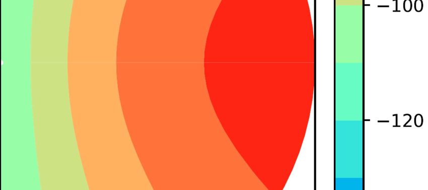
A&A proofs: manuscript no. Paper

plane of the orbit between the minor axis of the elongated orbit        and the velocities can be found as
and the observer. φobs is the viewing angle of the external ob-             2vc (R)
server, the angle between the line φ = 0 and the observer that is       vR =          lop (R) sin(φ0 )                                (34)
zero along the major axis of the orbits. (The explicit equations                v2t
                                                                                           lop (R)
                                                                                    "                      #
have been derived by Schoenmakers et al. 1997 and Schoenmak-
ers 1999).                                                              vφ =vc (R) 1 +              cos φ0                             (35)
                                                                                              v2t
The Cored Logarithmic Potentials
A simple model for a non-perturbed potential to cause a velocity        The line-of-sight velocity field is
pattern that corresponds to differential rotation (rising to flat ro-          X
tation, a rising rotation curve that tend to be flat at large radius)   vlos =    cn cos(nψ) + sn sin(nψ)                              (36)
is a cored logarithmic potential:                                                n
                                                                        vlos =[vR sin ψ + vϕ cos ψ] sin i                              (37)
            1 2
V0 (R) =     v ln[R2c + R2 ]                                    (24)
            2 0                                                         and
which has                                                               vlos = c1 cos ψ + c0 + s2 sin(2ψ) + c2 cos(2ψ)                 (38)
                 v0 R
vc (R) = p                                                      (25)    finally, one can obtain the measured harmonics as follows:
          R2 + R2c                                                                                !
                                                                             vc            3
where Rc and v0 are constants that v0 is circular velocity at large     c0 = 2 sin i                lop (R) cos φ1 ,              (39)
                                                                             vt       2(1 + α(R))
radius R. At R  Rc , this equation corresponds to a solid-body                                       !
rotation and at R  Rc the rotation curve is flat; So this model is              vc           1
                                                                        c2 = − 2 sin i                  lop (R) cos φ1 ,          (40)
a good representation of a rising-to-flat rotation curve (differen-              vt      2(1 + α(R))
tial rotation).                                                              vc            1
                                                                                                  !
The orbit in a non-rotating logarithmic potential (perturbed po-        s2 = 2 sin i                lop (R) sin φ1 ,              (41)
tential, planar non-axisymmetric potentials), which is just the              vt       2(1 + α(R))
potential of the harmonic oscillator is the sum of independent          c1 =vc sin(i).                                                 (42)
harmonic motions (Binney 1978; Binney J 1987).
For a potential that is perturbed by an m = 1 distortion and is         Note that the line-of-sight velocity field of a pure rotational disk
changed by first-order perturbation, we can take the net potential      (a disk in pure circular rotation) is vlos = vc (R) sin i cos ψ.
V at a given radius R to be a sum of the non-perturbed poten-
tial, V0 and the 1-th harmonic component of the perturbation,               For an m = 1 perturbation in the halo potential model, the
V1 (R) cos(φ), therefore the total potential                            line−of−sight velocity field is presented by equations (38)−(42).
                                                                        Our analysis is based on a reduced−χ2 as the goodness−of−fit
V(R, φ) = V0 (R) + V1 (R) cos φ,                                (26)    statistic. We have fitted the theoretical rotational velocity ex-
                                                                        tracted from the theoretical line−of−sight velocity field which
where we have chosen the the perturbation V1 (R) to have the            is a function of three free parameters, lop , ve and φ1 to the ob-
form (Jog 1997)                                                         served data points via a χ−squared minimization method (Least
V1 (R) = lop (R)v2e ,                                          (27)    Squares Fitting) for both of approaching and receding sides by
                                                                        programming in Python.
where lop is a small perturbation parameter and ve is the velocity
of the flat part of the rotation curve. So the net potential is         vlos = f (R, lop , ve , φ1 ).                                 (43)

V(R, φ) = V0 (R) + lop (R)v2e cos φ,                           (28)    The best−fit value of each parameter, lop , ve and φ1 in this model
                                                                        for best-fit to the observed rotation curve are obtained by mini-
with this choice for V1 (R) we have                                     mizing this function:
                                                                                          N "
            4lop                                                                             vc,the (Ri ) − vc,obs (Ri ) 2
                                                                                                                         #
a11 =                    ,                                                        1      X
                                                                (29)    χr =
                                                                         2
                                                                                                                            .           (44)
        v2t (1   + 2α)                                                        (N − M) i=1                  σi

        2(1 − 2α)lop                                                   The sum runs over the observational data points, with N, the to-
a31 =                        .                                  (30)    tal number of data points from the observed rotation curve and
           v2t (1 + 2α)                                                 M = 3, the number of free parameters. In equation (44), vc,obs (Ri )
The orbits can be found as follows                                      is the observed rotational velocity related with i-th data point at
                                                                        radius Ri , σi is the observational error bar related with each data
    R0                                                                point and vc,the is the theoretical rotational velocity of approach-
R = 2 1 − 2lop (R) cos φ0                                      (31)
    vt                                                                  ing and receding sides extracted from the line−of−sight velocity
                                                                        for an m = 1 perturbation in the potential model.
                                                                        Contrast to Kepley et al. (2007), we are able to fit the WLM ro-
             (3 − 2α)lop (R) sin φ0                                    tation curve simultaneously for both approaching and receding
φ = φ0 +                               ,                        (32)
                      v2t (1 − 2α)                                      sides with a lopsided halo potential model. Our results for value
                                                                        of the best fitting parameters for both of receding and approach-
where                                                                   ing sides are lop = 0.11, φ1 = 0◦ and ve = 44(km/s).
           vc (R)                                                            Figure 3 shows the extracted asymmetric rotation curve of
vt (R) =          ,                                             (33)    WLM from this model associated with an m = 1 perturbation
             ve
Article number, page 6 of 12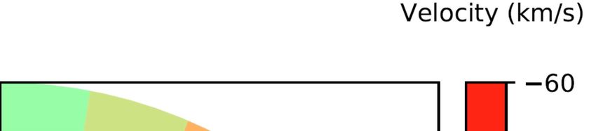
M. Khademi et al.: Kinematical Asymmetry in Dwarf Irregular Galaxy WLM and a Perturbed Halo Potential

                                                  Rotation Curve                           turbed orbits in a lopsided halo potential may be written as:
                           70
                                  Approaching Side from model                                                             iso cos φ
                                                                                                             "                        #
                                                                                                                 R
                           60     Receding Side from model                                 µ(R, φ) = µ0 exp −        (1 −            )                   (47)
                                  Approaching Side from data                                                    Rexp           2
                                  Receding Side from data
Circular Velocity (km/s)

                           50                                                              Where iso is the ellipticity of an isophote at R for m = 1 pertur-
                                                                                           bation, as follows:
                           40                                                                           Rmin   2∆R
                                                                                           iso = 1 −        =     ,                                     (48)
                           30                                                                           Rmax    R
                                                                                           where Rmax is the maximum extent of an isophote and Rmin is the
                           20                                                              minimum extent of that isophote.
                                                                                           By using the equation of continuity and the relations for the or-
                           10
                                                                                           bits (coordinates and velocities), one can obtain the relation be-
                           0                                                               tween iso and lop at a given radius R (Jog 2000):
                            0.0    0.5      1.0      1.5       2.0   2.5      3.0
                                                                                            iso
                                                                                                               !
                                                    Radius (kpc)                                 =4 1−
                                                                                                         Rexp
                                                                                                                 .                                       (49)
                                                                                           lop           2R
Fig. 3. Asymmetric rotation curve extracted from the perturbed halo
potential (lopsided halo potential) model and from the observational                       For this lopsided halo potential model (a global m = 1 in the po-
data (Kepley et al. 2007) for the approaching and the receding sides                       tential) By using the equations (47) and (49) and programming
of WLM. A perturbed halo potential (a global m=1 mode in the poten-                        in Python, we have extracted the surface density distribution map
tial) can create kinematical asymmetry between two halves of galaxy                        in the X-Y plane for the gaseous disk in Figure 4c and the stel-
and. By comparing the shape of rotation curve and asymmetry between                        lar disk in Figure 4d for an m = 1 perturbation in the potential
approaching side and receding side obtained from lopsided halo poten-                      with lop = 0.11 which is the best-fit value of this parameter for
tial model with the the shape of observed rotation curves for two sides                    best fit to the observed rotation curve in Figure 3. These Fig-
of this galaxy, one can see the good agreement between correspond-                         ures which show the surface density contours of the lopsided
ing gas kinematics of a perturbed halo potential and the observed gas
kinematics.
                                                                                           disc (a global m = 1 mode), indicate the azimuthal variation in
                                                                                           the surface density for an exponential disk in a lopsided halo po-
                                                                                           tential. The isophotal shapes have aligned egg-shaped contours
in the halo potential (a lopsided halo potential model) and also                           and the center of the inner isophotes are displaced from the cen-
asymmetric rotation curve from the observational data by Kep-                              ter of the outer isophotes (see Jog 1997). The outward contours
ley et al. (2007).                                                                         are more and more deviated from the unperturbed surface den-
By comparing the shape of rotation curve and asymmetry be-                                 sity contours, showing a more lopsided distribution in the outer
tween approaching side and receding side obtained from lop-                                regions.
sided halo potential model with the the shape of observed rota-                                For this perturbed potential, by using the measured har-
tion curves for two sides of this galaxy (see Figure 3), one can                           monics and other equations in this section and programming in
see the good agreement between corresponding gas kinematics                                Python, we have also mapped the velocity field in Figure 5 for
of a perturbed halo potential and the observed gas kinematics.                             an m = 1 perturbation in the potential. This perturbed velocity
So a lopsided halo potential model can explain the asymmetry in                            field map like the observational velocity field map (see Figure
the kinematic data reasonably well.                                                        5 of Kepley et al. 2007) is clearly asymmetric and shows the
     By considering that the non-perturbed surface density have                            strong curvature of the iso−velocity contours on one side and
an exponential dependence on radius as:                                                    the weaker curvature on the other side (iso−velocity contours
                  "      #                                                                 are more curved on one side than them on the other side).
                     R                                                                     So lopsided gravitational potential of a dark matter halo can pro-
µun (R) = µ0 exp −                                          (45)                           duce an asymmetry in the rotation curve of WLM, in the velocity
                    Rexp
                                                                                           field map and in the morphology of the galaxy; gas surface den-
where µ0 is the central surface density and Rexp is the expo-                              sity and stellar surface density (see also Jog 1997) between two
nential disk scale length. We showed a non-perturbed surface                               sides of this galaxy. So such a (cos φ) asymmetry of type m = 1
density map for the exponential gaseous disk in Figure 4a and                              potential perturbation in the halo potential ( the lopsidedness of
the exponential stellar disk in Figure 4b.                                                 the dark matter halo) can create such a kinematical asymmetry
                                                                                           between two sides of this galaxy.
    A lopsided gravitational halo potential can perturb an ax-                                 In Table (2), column (1) gives the exponential stellar disk
isymmetric galactic disk as the disk surface density responds to                           scale length for inner part, column (2) gives the exponential stel-
the total asymmetry (Jog 2000). Since the circular velocity varies                         lar disk scale length for outer part and column (3) gives the ex-
along the perturbed orbit, the related surface density also varies                         ponential gaseous disk scale length. column (4) gives the loga-
as a function of the azimuthal angle φ. This changes for particles                         rithm of central surface density for stellar disk, column (5) gives
(gas and stars) on these orbits are governed by the equation of                            the central surface density for HI gas disk, column (6) gives the
continuity:                                                                                central surface density for total gas (HI and He) disk and finally
                                                                                           column (7) gives the HI radius.
   ∂                ∂ h              i
      Rµ(R, φ)vR (φ) +    µ(R, φ)vφ (φ) = 0                                         (46)
  ∂R                   ∂φ                                                                  4. Classification based on pure kinematics
According to the equation of continuity and paper (Jog 1997),                              Extremely lopsided mass distribution seems to occur in strongly
the effective surface density for an exponential disk with per-                            disturbed galaxies with ongoing merger events or those have
                                                                                                                                  Article number, page 7 of 12
A&A proofs: manuscript no. Paper
12.0 1.6
3 3 1.4
10.5
2 9.0
2 1.2
1
Stellar(MSun/pc 2)
1 7.5 1.0
Gas(MSun/pc 2)
0 6.0 0 0.8
1 4.5 1 0.6
3.0 2 0.4
2
1.5 3 0.2
3
0.0 0.0
3 2 1 0 1 2 3 2 0 2
(a) (b)
12.0 1.6
3 3
10.5 1.4
2 2 1.2
9.0
1
Stellar(MSun/pc 2)
1 7.5 1.0
Gas(MSun/pc 2)
0 6.0 0 0.8
1 4.5 1 0.6
3.0 2 0.4
2
1.5 0.2
3 3
0.0 0.0
3 2 1 0 1 2 3 3 2 1 0 1 2 3
(c) (d)
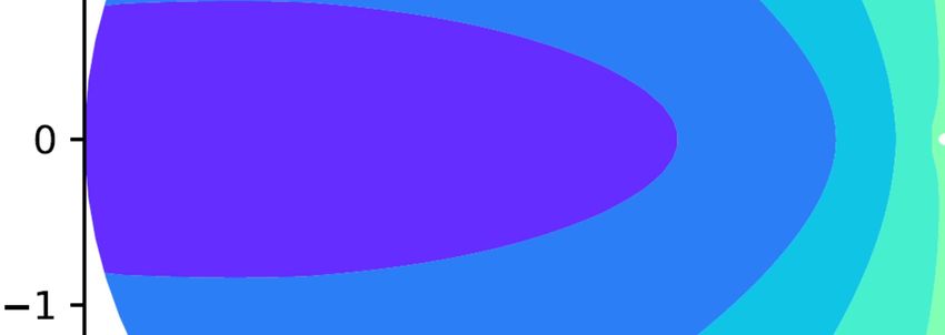
Fig. 4. (a): Exponential gaseous disk surface density map for a non-perturbed halo potential. (b): Exponential stellar surface density map for a
non-perturbed halo potential. (c): Asymmetric gas surface density map associated with a lopsided (perturbed) halo potential model-cube (Contours
of constant surface density for an m = 1 perturbation in the potential). (d): Asymmetric stellar surface density map associated with a lopsided
(perturbed) halo potential model-cube. All of these surface density distribution maps have been projected in the X-Y plane. The exponential
gaseous disk scale length Rexp,gas = 1.04kpc and the central surface density for total gas (HI and He) disk, µ0,gas = 11.2MS un /pc2 . The exponential
stellar disk scale length Rexp,stellar = 1.24kpc and the central surface density for stellar disk, µ0,stellar = 1.4MS un /pc2 . There is symmetry between
two halves of gaseous disk surface density map in Figure (a) and stellar disk surface density map in Figure (b) in a non-perturbed halo potential
and there is asymmetry between two halves of gaseous disk surface density map in Figure (c) and stellar disk surface density map in Figure (d) in
a perturbed (lopsided) halo potential.
undergone a recent merger (Jog 1997). Such non-axisymmetry (e.g., Bournaud et al. 2005; Zaritsky & Rix 1997; Mapelli
in the luminosity distribution and in the mass distribution with et al. 2008). Thus, a disturbed structure in a galaxy may result
the isophotes which are off-centered with respect to each other from such interacting processes with former companions that
is seen in the centers of mergers of galaxies (Jog & Maybhate occurred sufficiently long ago, no longer existing (Fulmer et al.
2006). For an m = 1 perturbation in the potential, the isophotal 2017). Therefore, It is possible that even an isolated galaxy
shapes have aligned egg-shaped contours (Jog 1997) as we have may hold signs of an earlier minor merger such as central
plotted in Figures 4c and 4d, the center of the inner isophotes asymmetry, and a tidal stream for a few Gyr after the merger,
are displaced from the center of the outer isophotes. as shown by observational evidence for very isolated spiral
Lopsidedness is a deviation from the ideal case that might occur galaxy NGC5523 that supports the idea that some galaxies
in a disk. What would be the origin of the dark matter halo may have become isolated because they have experienced a
lopsidedness for an isolated galaxy? A variety of processes historic merger with former companions (Fulmer et al. 2017).
such as gas accretion, interactions, and minor mergers can Fulmer et al. (2017) have favored a historic (in the recent past)
excite asymmetries and an m = 1 lopsidedness in disc galaxies merger as the source of perturbation that produced a long-lived
Article number, page 8 of 12
M. Khademi et al.: Kinematical Asymmetry in Dwarf Irregular Galaxy WLM and a Perturbed Halo Potential

Table 2. The exponential disk scale lengths Rexp and the central surface densities µ0 for WLM

                           (1)             (2)           (3)           (4)               (5)            (6)         (7)
                         Rexp,?          Rexp,?       Rexp,gas      log(µ0,? )          µ0,HI          µ0,gas       RHI
                     (inner) (kpc) (outer) (kpc)       (kpc)     log(MS un /pc2 ) (MS un /pc2 ) (MS un /pc2 ) (kpc)
                                a              a             b
                          1.24            0.57          1.04          0.15a               8 c, d       11.2         3.5 d
                        References: (a) (Zhang et al. 2012), (b) (Read et al. 2019), (c) (Oh et al. 2015) and (d) (Kepley
                        et al. 2007),

                                                                             scribed in (Krajnović et al. 2006; Shapiro et al. 2008).
                                                                             A velocity field map can be divided into a number of elliptical
                                                                             rings and along each elliptical ring, the moment is decomposed
                                                                             into the Fourier series
                                                                                             X
                                                                             vlos (ψ) = c0 +    cn cos(nψ) + sn sin(nψ),               (50)
                                                                                              n=1

                                                                             where c0 , gives the systemic velocity of each elliptical ring. This
                                                                             yield velocity profiles to be described by a finite number of har-
                                                                             monic terms via Fourier series as well. So we can express the
                                                                             line-of-sight velocity as
                                                                                                   X
                                                                             vlos (R, ψ) = v sys +   cn cos(nψ) + sn sin(nψ).                (51)
                                                                                                    n=1

                                                                             The observed line-of-sight radial velocity fields for an ideal ro-
                                                                             tating disk (pure rotating disk in pure circular rotation) are ex-
                                                                             pected to be dominated by the cos(ψ) term and are fitted with no
                                                                             radial or out of plane motion. So the power in the c1 term there-
Fig. 5. Perturbed velocity field map caused by a lopsided halo poten-        fore represents the circular rotation at each ring, while power in
tial model-cube with a perturbation (a global m=1 mode in the poten-         the other coefficients (normalized to the rotation curve, c1 ) repre-
tial), projected in X-Y plane. The Perturbed velocity field map is clearly   sents deviations from pure circular motion (Shapiro et al. 2008).
asymmetric. This model shows strong curvature of the iso-velocity con-       From the kinemetry decomposition, the amplitude kn of each
tours on one side and weaker curvature on the other side. The HI kine-       Fourier harmonic order n is obtained from the cn and sn coef-
matics is slightly lopsided. A perturbed potential can produce the asym-     ficients (Krajnović et al. 2006):
metric velocity fields.
                                                                                   q
                                                                             kn = c2n + s2n .                                                 (52)
asymmetry in NGC5523. asymmetry in galaxies has been also
found in low-density environments without any direct signs                   The information about kinematic asymmetries in the velocity
for recent interactions (Matthews & Gallagher 1997, 2002).                   field of galaxies is contained in higher order terms than k1 . So
Recently Ghosh et al. (2021) have done a simulation study of                 the average amplitude of velocity asymmetries kavg has been de-
lopsided asymmetry generated in a minor merger to investigate                fined by a limited number of terms:
the dynamical effect of the minor merger of galaxies on the
excitation of lopsidedness. They have shown that a minor                                1 X
                                                                                              m
merger can trigger an m = 1 lopsided distortions in the stellar              kavg =             kn .                                         (53)
and gas velocity field of the host galaxy and its stellar density.                    m − 1 n=2
We are going to determine the strength of such a deviation of the
velocity field from the ideal rotating disk case and investigate             If the potential includes a perturbation of harmonic number m,
whether merger could have created such a lopsidedness in the                 the line-of sight velocity field includes m + 1 and m − 1 terms. In
halo potential.                                                              the case of a harmonic number m = 1 term in the potential, i.e.
                                                                             a global m = 1 mode in the potential, the line−of−sight velocity
                                                                             field will include an m = 0 term and an m = 2 term. Therefore for
                                                                             this perturbed potential model, the information about kinematic
4.1. Kinemetric Analysis, Quantifying Asymmetries with                       asymmetries is contained in term k2 which is higher order than
     Kinemetry and Merger/Disk classifications based on                      k1 .
     kinematic asymmetries:                                                  The amplitude k2 of Fourier harmonic order n = 2 is calculated
                                                                             from the c2 and s2 coefficients:
Kinematics provides the only way to infer whether a galaxy is
dominated by a relaxed rotation or by gravitational perturba-                      q
tion often linked with major merger events or minor merger and               k2 = c22 + s22 ,                                              (54)
galaxy interactions.
The asymmetries in the kinematic of galaxy like the asymmetries              which c2 and s2 coefficients has calculated in section (3.1.1).
that seen in the velocity field map and rotation curve of galaxy             By normalizing this average deviation kavg to the pure circular
can be measured via the kinemetry method developed and de-                   motions as measured by c1 , we can derive the relative level of
                                                                                                                      Article number, page 9 of 12
A&A proofs: manuscript no. Paper
deviation of the velocity field from that of an ideal rotating disks For obtaining the deviations from pure rotational velocity (cir-
or asymmetry vasym (Shapiro et al. 2008). cular motion), we have plotted the amplitude of velocity asym-
* + metries k2 in term of radius for an m = 1 perturbation in the
kavg,v potential in Figure (6b) based on kinematic asymmetries.
vasym = , (55)
c1 R Also we have determined the strength of deviation of the veloc-
ity field, vasym from the ideal rotating disk case (a purely rotating
where the average is over all radii. This can be applied to velocity disk) by obtaining the relative level of deviation of the velocity
dispersion field too. But for the velocity dispersion field, c0,σ is field from that of an ideal rotating disks or the asymmetry in the
the only nonzero kinemetry coefficient for an ideal rotating disk. velocity field, vasym for the perturbed potential model from an
So the information about kinematic asymmetries in the velocity ideal disk (with vasym = 0 and σasym = 0 ) in terms of radius
dispersion field is contained in the amplitudes k1,σ − km,σ . So the in Figure (6c) by normalizing the average deviation kavg (here
average amplitude of velocity dispersion asymmetries kavg,σ has kavg = k2 ) to the pure circular motions as measured by c1 .
been defined via a limited number of terms: For obtaining Figures 6a, 6b and 6c we have averaged between
m
1X two sides (approaching and receding sides), so we have ne-
kavg,σ = kn,σ , (56) glected the asymmetry between the two sides which is the domi-
m n=1
nant asymmetry in the WLM velocity field. And also in addition
and the asymmetry in the velocity dispersion field is defined as to vasym , Kasym contains σasym too, and σasym is bigger than zero,
(Shapiro et al. 2008): since the dispersion map is indeed presenting a minimum at cen-
* + ter, which is not expected for an ideal rotating disk (Hammer
kavg,σ et al. 2017). So Kasym value will be higher than vasym , which is
σasym = . (57)
c1 R shown in Figure 6c. Then it is possible that WLM lies in the
transition region, in which disk and merger coexist. So merger
The average amplitude of velocity asymmetries kavg for the per- may be one of the possible origins of the dark matter halo lop-
turbed potential model (an m = 1 perturbation in the potential): sidedness for this isolated galaxy (according to the classification
by Bellocchi et al. 2016).
kavg = k2 (58)
So asymmetry vasym or the relative level of deviation of the ve- 4.2. Classification based on σ centering
locity field from that of an ideal disks for this model (a global It has been defined another parameter ∆r which is the distance
m = 1 mode in the potential) is given by between the σ peak (cσ ) and dynamical centre (cV F ) (Flores et al.
*
kavg,v
+ * +
k2 2006)
vasym = = . (59)
c1 R c1 R ∆r = |cσ − cV F |. (60)
The Merger/ Disk classifications based on kinemetry analysis
are used to kinematically classify galaxies in disk and merger. The kinematics of IMAGES galaxies has been visually classified
This method relies on velocity asymmetries and can be used using this parameter and and the alignment of both kinematic
to distinguish unvirialized systems or those involved in major and optical P. A (Flores et al. 2006; Yang et al. 2008). It has lead
merger events from galaxies dominated by ordered rotational to three classes of Kinematics:
motion and one can differentiate disks and mergers based on • Rotating disks:
symmetries of warm gas kinematics. We determine the strength Rotating disks have a prominent signature in their velociy dis-
of such a deviation of the velocity field from the ideal rotat- persion map, expressed as a central peak at the dynamical centre
ing disk case to investigate whether merger could have cre- (with ∆r ∼ 0). The velocity field show an ordered gradient and
ated such a lopsidedness in the halo potential. An ideal rotat- the rotation’s axis in the velocity field almost aligned with the
ing disk in equilibrium is expected to have an ordered veloc- optical major axis (the kinematical major axis is aligned with the
ity field, described by the spider−like diagram and a centrally morphological major axis) and the σ-map (velocity dispersion
peaked velocity dispersion field (Shapiro et al. 2008). It has map) shows a single peak close to the kinematical center, σ
been showed that the merger templates have vasym and σasym maps should show a clear peak near the galaxy dynamical centre
larger than 0.5 where the velocity gradient in the rotation curve is the steepest
q(Shapiro et al. 2008). There is a defined param- (Flores et al. 2006; Puech et al. 2006; Yang et al. 2008).
eter Kasym = (v2asym ) + (σ2asym ), total kinematic asymmetry, for • Perturbed rotations:
which has been established Kasym,opt = 0.5 as an optimal empir- The velocity field shows rotation (the kinematics shows all the
ical limit for separating the two classes and the classification of features of a rotating disk) and the axis of rotation in the velocity
a system as a disk or merger can be done by this limit and major field is aligned with the optical major axis but the σ-map shows
mergers or unvirialized systems can be identified via Kasym > 0.5 a peak that clearly shifted away from the kinematical centre
(Shapiro et al. 2008). Bellocchi et al. (2016) has kinematically (with ∆r > 0) or does not show any peak (Flores et al. 2006;
classified galaxies as disk with a Kasym < 0.16(0.14), merger Puech et al. 2006; Yang et al. 2008).
with a Kasym > 0.94(0.66) and the galaxies lie in the transition • Complex kinematics:
region, in which disks and mergers coexist, with 0.16(0.14) < Systems with near chaotic velocity field, both velocity field
Kasym < 0.94(0.66). For the ideal case (vasym ≡ 0 and σasym ≡ 0). map and σ-map (velocity dispersion map) display complex
However it requires a finer adjustment of the limit distinguishing distributions, very different from that expected for rotating
mergers from rotating disk. disks, neither the velocity field map nor the σ-map (velocity
For WLM, in Figure (6a), we have plotted c1 , pure circular ve- dispersion map) are compatible with regular rotation, including
locity in terms of radius i.e. the rotation curve for an ideal rotat- the velocity fields that not aligned with the optical major axis
ing disk in pure circular motions. (Flores et al. 2006; Puech et al. 2006; Yang et al. 2008, see also
Article number, page 10 of 12M. Khademi et al.: Kinematical Asymmetry in Dwarf Irregular Galaxy WLM and a Perturbed Halo Potential
Rotation curve for an ideal rotating disk Hung et al. 2015).
In a minor merger, the disk is not destroyed, and the kinematics
35 of the remnant doesn’t appear too complex. The galaxy should
be observed still rotating along its main optical axis with a
30 dispersion map that does not show any peak at the centre. This
Circular velocity (km/s)
could correspond to the perturbed galaxies (Puech et al. 2006).
25 An ideal rotating disk in equilibrium is expected to have an
ordered velocity field, described by the spider diagram structure,
20 and a centrally peaked velocity dispersion field and the observed
velocity fields are fitted with circular velocity and with no radial
15 or out of plane motions (non−circular motions) (Shapiro et al.
2008). The galaxies with the main kinematics gradient well
10 aligned with respect to the principal morphological axis can be
described as a rotating disk (Plummer 1911).
5 For WLM, the rotation (an ordered velocity field, described by
the iso-velocity contours with spider diagram structure) is seen
0 in the observational velocity field map. The velocity field shows
0.0 0.5 1.0 1.5 2.0 2.5 3.0 3.5 4.0 rotation (see Figure. 5 of Kepley et al. 2007). The kinematics
Radius (kpc) shows all the features of a rotating disk and the axis of rotation
(a)
in the velocity field follows the optical major axis (see optical
images of WLM in Little Things Data), but the velocity disper-
sion (Second moment) map for WLM does not show any peak
9
The amplitude of velocity asymmetries in terms of radius at the centre, which is not expected for an ideal rotating disk
The amplitude of velocity asymmetries (km/s)
(see Figure. 6 of Kepley et al. 2007 and Figure. 6, bottom left of
8 Ianjamasimanana et al. 2020). The strong asymmetry between
two sides (approaching and receding sides) of the galactic
7 rotation curve indicates an abnormal rotation. So this galaxy
6
is not an ideal rotating disk, but a rotating disk with perturbed
rotations and non−circular motions in addition to pure circu-
5 lar motion and its kinematics is classified as a perturbed rotation.
4
3 4.3. The morpho-kinematic classification
2 Neichel et al. (2008) found a great agreement between the kine-
matic classification and classification based on pure morpholog-
1 ical analysis. Hammer et al. (2009) defined 3 different morpho-
kinematical classes:
0 • Rotating spiral disks are galaxies that show a rotating velocity
1.0 1.5 2.0 2.5 3.0
Radius (kpc) field and a dispersion peak at the dynamical centre (see e.g. Flo-
res et al. 2006), and with the appearance of a spiral galaxy.
(b) • Non−relaxed (Nonvirialized) systems are galaxies with veloc-
ity fields incompatible from a rotational velocity field and with
0.35
Level of deviation from an ideal rotating disk in terms of radius peculiar morphology.
• Semi−relaxed (Semivirialized) systems show either a rota-
tional velocity field and a peculiar morphology or a velocity field
0.30 incompatible from rotation and a spiral morphology.
Asymmetry in the Velocity Field
This kind of classification and the degree of virialization scheme
0.25 has been presented by Hammer et al. (2009).
According to the above, WLM seems to be intermediate between
0.20
non−virialized and semi−virialized systems.
0.15
5. Conclusion
0.10 To investigate the origin of the strong asymmetric rotation curve
of the dwarf irregular galaxy WLM, we examined whether an
m = 1 perturbation (lopsidedness) in a halo potential could be a
0.05 mechanism creating such kinematical asymmetry. To do so, we
fit the rotation curve of a lopsided halo potential model to that
0.00 of WLM. There is a good agreement between corresponding gas
1.0 1.5 2.0 2.5 3.0 3.5
Radius (kpc) kinematics of a perturbed halo potential and the observed gas
kinematics of WLM. Contrary to Kepley et al. (2007), our model
(c) provides a good fit to the WLM rotation curve simultaneously for
Fig. 6. (a): The rotation curve for an ideal rotating disk in pure circular Article number, page 11 of 12
motions, c1 in terms of radius R. (b): The amplitude of velocity asym-
metry k2 in terms of radius R. (c): the level of deviation from an ideal
rotating disk or the asymmetry in the velocity field vasym in terms of
radius.A&A proofs: manuscript no. Paper
both approaching and receding sides with a lopsided halo poten- Kepley, A., Wilcots, E., Hunter, D., & Nordgren, T. 2007, Astron. J., 133, 2242
tial model with the best-fitting parameters of lop = 0.11, φ1 = 0◦ Krajnović, D., Cappellari, M., de Zeeuw, P. T., & Copin, Y. 2006, MNRAS, 366,
and ve = 44(km/s). For this best-fitting model, we mapped the 787
Lelli, F., Verheijen, M., Fraternali, F., & Sancisi, R. 2012, A&A, 544, A145
surface density field for gas disk and stellar disk, as well as the Levine, S. E. & Sparke, L. S. 1998, The Astrophysical Journal, 496, L13
velocity field. The latter shows asymmetric characteristics that is Lovelace, R. V. E., Zhang, L., Kornreich, D. A., & Haynes, M. P. 1999, The
comparable to the observed one, e.g., Figure. 5 in (Kepley et al. Astrophysical Journal, 524, 634
2007). We conclude that a lopsided halo potential model can ex- Mapelli, M., Moore, B., & Bland-Hawthorn, J. 2008, MNRAS, 388, 697
Matthews, L. D. & Gallagher, J. S., I. 2002, ApJS, 141, 429
plain the asymmetry in the kinematic data reasonably well. Matthews, L. D. & Gallagher, John S., I. 1997, AJ, 114, 1899
WLM shows an ordered velocity field (see Figure. 5 of Ke- McConnachie, A. W. 2012, The Astronomical Journal, 144, 4
pley et al. 2007) and the kinematical axis well aligned with the Navarro, J. F., Frenk, C. S., & White, S. D. M. 1996, ApJ, 462, 563
optical major axis. But its velocity dispersion map does not show Neichel, B., Hammer, F., Puech, M., et al. 2008, A&A, 484, 159
any peak at the centre (see the Figure. 6 of Kepley et al. 2007 Noordermeer, E., Sparke, L. S., & Levine, S. E. 2001, Monthly Notices of the
Royal Astronomical Society, 328, 1064
and the Figure. 6 of Ianjamasimanana et al. 2020) which is not Oh, S.-H. et al. 2015, Astron. J., 149, 180
expected for an ideal rotating disk. We studied the kinematical Plummer, H. C. 1911, Monthly notices of the royal astronomical society, 71, 460
classification of the velocity field of WLM with various meth- Puech, M., Hammer, F., Flores, H., Östlin, G., & Marquart, T. 2006, A&A, 455,
ods (see Setc. 4). We found that its velocity field is significantly 119
Read, J. I., Walker, M. G., & Steger, P. 2019, MNRAS, 484, 1401
perturbed because of both its asymmetrical rotation curve, and Richter, O. G. & Sancisi, R. 1994, A&A, 290, L9
also because of its peculiar velocity dispersion map. Based on Schoenmakers, R. 1999, PhD thesis
kinemetry analysis, we determined the strength of such a devi- Schoenmakers, R., Franx, M., & de Zeeuw, P. 1997, Mon. Not. Roy. Astron.
ation of the velocity field from the ideal rotating disk case by Soc., 292, 349
obtaining the relative level of deviation of the velocity field from Shapiro, K. L., Genzel, R., Förster Schreiber, N. M., et al. 2008, ApJ, 682, 231
Sofue, Y. & Rubin, V. 2001, ARA&A, 39, 137
that of an ideal rotating disks case. Thus, it is possible that WLM Swaters, R., Schoenmakers, R., Sancisi, R., & van Albada, T. 1999, Mon. Not.
lies in the transition region, in which disk and merger coexist. So Roy. Astron. Soc., 304, 330
merger may be one of the possible origins of the dark matter halo Swaters, R. A., van Albada, T. S., van der Hulst, J. M., & Sancisi, R. 2002, A&A,
lopsidedness for this isolated galaxy. In conclusion, it appears 390, 829
Yang, Y., Flores, H., Hammer, F., et al. 2008, A&A, 477, 789
that the rotation curve of WLM diverges significantly from that Zaritsky, D. & Rix, H.-W. 1997, ApJ, 477, 118
of an ideal rotating disk, which may significantly affect investi- Zhang, H.-X., Hunter, D. A., Elmegreen, B. G., Gao, Y., & Schruba, A. 2012,
gations of its dark matter content. AJ, 143, 47
Acknowledgements. The authors would like to thank the anonymous referee for
her/his precise and constructive comments. M. Khademi would like to thank the
GEPI Group (Observatoire de Paris) for their hospitality and their support. M.
Khademi and S. Nasiri would like to thank Shahid Beheshti University.
References
Baldwin, J. E., Lynden-Bell, D., & Sancisi, R. 1980, MNRAS, 193, 313
Beale, J. S. & Davies, R. D. 1969, Nature, 221, 531
Bellocchi, E., Arribas, S., & Colina, L. 2016, A&A, 591, A85
Binney, J. 1978, MNRAS, 183, 779
Binney J, T. S. 1987, Galactic Dynamics
Bournaud, F., Combes, F., Jog, C., & Puerari, I. 2005, Astron. Astrophys., 438,
507
Bournaud, F., Jog, C. J., & Combes, F. 2005, A&A, 437, 69
Cole, S. & Lacey, C. 1996, MNRAS, 281, 716
Dale, D. A., Cohen, S. A., Johnson, L. C., et al. 2009, ApJ, 703, 517
Edmondson, F. K. 1961, Science, 134, 464
Flores, H., Hammer, F., Puech, M., Amram, P., & Balkowski, C. 2006, A&A,
455, 107
Fulmer, L. M., Gallagher, J. S., & Kotulla, R. 2017, A&A, 598, A119
Ghosh, S. & Jog, C. J. 2018, New Astronomy, 63, 38
Ghosh, S., Saha, K., Jog, C. J., Combes, F., & Di Matteo, P. 2021, arXiv e-prints,
arXiv:2105.05270
Hammer, F., Flores, H., Puech, M., et al. 2009, A&A, 507, 1313
Hammer, François Puech, M., Flores, H., & Rodrigues, M. 2017, Studying Dis-
tant Galaxies: a Handbook of Methods and Analyses
Haynes, M. P., Hogg, D. E., Maddalena, R. J., Roberts, M. S., & van Zee, L.
1998, The Astronomical Journal, 115, 62
Heller, A. B., Brosch, N., Almoznino, E., van Zee, L., & Salzer, J. J. 2000, MN-
RAS, 316, 569
Hung, C.-L., Rich, J. A., Yuan, T., et al. 2015, ApJ, 803, 62
Ianjamasimanana, R., Namumba, B., Ramaila, A. J. T., et al. 2020, MNRAS,
497, 4795
Iorio, G., Fraternali, F., Nipoti, C., et al. 2017, MNRAS, 466, 4159
Jog, C. J. 1997, The Astrophysical Journal, 488, 642
Jog, C. J. 1999, ApJ, 522, 661
Jog, C. J. 2000, The Astrophysical Journal, 542, 216
Jog, C. J. 2002, Astronomy & Astrophysics, 391, 471
Jog, C. J. & Combes, F. 2009, Physics Reports, 471, 75
Jog, C. J. & Maybhate, A. 2006, Monthly Notices of the Royal Astronomical
Society, 370, 891
Article number, page 12 of 12You can also read