BMP RAM FIELD PROTOCOLS V4 .8 - BEST MANAGEMENT PR ACTICES R APID ASSESSMENT METHODOLOGY - 2ndnature
←
→
Page content transcription
If your browser does not render page correctly, please read the page content below
B E S T M A N A G E M E N T P R A C T IC E S
R A P I D A S S E S S ME N T M E T H ODOL OG Y

B MP R AM
FI E LD PR O TO CO LS V 4.8
FINAL
June 2019
|1

     Best Management Practices Rapid Assessment Methodology

                                         (BMP RAM)

                             Field Observation Protocols V 4.8

                                           June 2019

                                 Technical elements developed by:

Recommended citation:

2NDNATURE 2019. Best Management Practices Rapid Assessment Methodology (BMP RAM) Field
Observation Protocols v4.8. June 2019.

     500 Seabright Avenue, Suite 205 | Santa Cruz, CA 95062 | 2ndnaturewater.com | 831.426.9119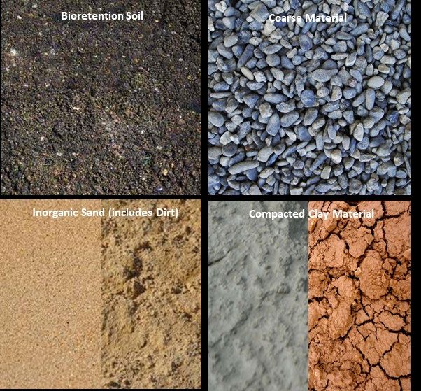
|2

Background

BMP RAM v4.8 (released in June 2019) was collectively vetted with a selection of municipal stormwater
managers and their respective regulatory representative at the Central Coast Regional Water Quality
Control Board to identify priority technical and data management refinements to better balance
municipal work flow needs and information required to evaluate regulatory compliance. Based on these
feedback, BMP RAM v4.0 includes technical refinements and functional improvements toward a simple,
practical and user-friendly tool, fully integrated with the 2NFORM Stormwater Software Suite. Even with
these improvements, BMP RAM technical approach and data management platform will continually be
improved and maintained to meet the needs of stormwater managers, funders, regulators and the
community within the concise mission defined for the tool. User feedback is encouraged to ensure useful
and feasible BMP RAM improvements are identified, allowing continued effective iterations.

Legal Notices

BMP RAM is the exclusive intellectual property of 2NDNATURE Software Inc. Use of BMP RAM is subject to the
terms and conditions of an agreement executed with 2NDNATURE Software Inc. prior to access being given
to such product.

Copyright © 2019. 2NDNATURE Software Inc.

Information in this Field Observation Protocols document and all 2NDNATURE technical support policies are
subject to change without notice.

This Field Observation Protocols document is provided “as is” and without warranty of any kind. 2NDNATURE
Software Inc. expressly disclaim all warranties, expressed or implied, including, but not limited to, the implied
warranties of merchantability and fitness for a particular purpose and against infringement.

US Patent Application 62/534,173 Systems and Methods for Event-based Modelling of Runoff and Pollutant
Benefits of Sustainable Stormwater Management.

2NDNATURE Software Inc.
500 Seabright Avenue, Suite 205
Santa Cruz, CA 95062
Phone +1 831 426 9119
Fax +1 831 426 7092
http://www.2ndnaturewater.com/

|3

                                                               C ONTENTS
Field Observations by Structural BMP Type ........................................................................................................... 4

BMP RAM Equipment List .......................................................................................................................................... 5

Constant Head Permeameter (CHP)..................................................................................................................... 7

Conveyance ............................................................................................................................................................ 10

Infiltrometer ............................................................................................................................................................... 12

Material Accumulation – Staff Plate .................................................................................................................... 15

Material Accumulation – Stadia Rod................................................................................................................... 17

Permeability .............................................................................................................................................................. 21

Standing Water- Closed Space BMPs .................................................................................................................. 24

Substrate Type .......................................................................................................................................................... 26

Vegetation Cover ................................................................................................................................................... 29

 500 Seabright Avenue, Suite 205 | Santa Cruz, CA 95062 | 2ndnaturewater.com | 831.426.9119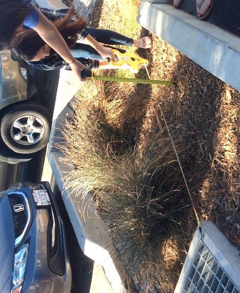
|4
Field Observations by Structural BMP Type
Benchmark Benchmark
Structural BMP Type Field Observations Structural BMP Type Field Observations
Observations Observations
Material
Bed Filter
Permeability Accumulation
(Stadia Rod)
Conveyance Biofiltration Substrate Type
Material
Detention Accumulation Permeability
Basin
Conveyance Conveyance
Material
CHP or
Infiltrometer Accumulation
(Stadia Rod)
Dry Basin Vegetation Cover Bioretention Substrate Type
Material
Accumulation Permeability
Centralized BMPs
Conveyance Conveyance
CHP or
Vegetation Cover
Decentralized BMPs
Infiltrometer
Infiltration Basin Bioswale
Vegetation Cover Permeability
Conveyance Conveyance
Material
Standing Water Accumulation
Media Filter Sediment Trap (Stadia Rod)
Conveyance Conveyance
Material
Treatment Accumulation Vegetation Cover
Vault Infiltration
Conveyance Permeability
Feature
Material
Accumulation Conveyance
Wet Basin Vegetation Cover Pervious Permeability
Conveyance Pavement Conveyance
Material
Settling Basin Accumulation
Conveyance
Material
Filtration Device
Accumulation
(Stadia Rod)
Conveyance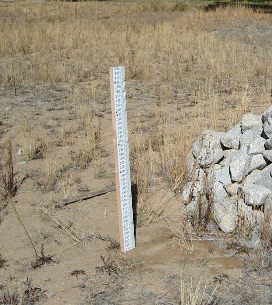
|5

                                     BMP RAM Equipment List
     The table below provides the equipment needed to carry out the various BMP RAM field protocols/
     assessments. Links and some photos of equipment are included as a reference, where relevant. Equipment
     can be found through a variety of sources and users are welcome to purchase from any vendor Users are
     encouraged to review the field protocols and inventoried BMPs before purchasing all equipment to
     determine which equipment is needed to carry out assessments.

   Field Protocol                     Equipment Needed                                  Example

                        3-5 gallon jug or carboy to transport water

                        Map of BMPs
      General
                        Field Protocols

                        Field Datasheets (hard copy or mobile device)

   Conveyance           No additional equipment is needed

                        Double Ring Infiltrometer
                        Recommend 12" diameter and 4" high
                        http://www.turf-tec.com/IN7lit.html

                        Double Ring Driving Plate
                        http://www.turf-tec.com/IN6lit.html
    Infiltrometer
                        Rubber Mallet

                        Stop Watch
                        Gallon Containers / Water

                        Tape Measure / Ruler

                        Staff Plate
                        https://tinyurl.com/y8ef5dgg

Material Accumulation
     (staff plate)      Mounting equipment is needed to install in BMP
                        (this may vary depending on basin type). Picture
                        at the right has staff plated installed in
                        permeable surface mounted on wood 2x4.

           500 Seabright Avenue, Suite 205 | Santa Cruz, CA 95062 | 2ndnaturewater.com | 831.426.9119
|6

  Field Protocol                Equipment Needed                    Example

                   Telescoping Stadia Rod
                   https://tinyurl.com/yaqwt3f4

    Material       Halogen Flashlight
 Accumulation
  (stadia rod)     Tape Measure x 2

                   Hand-held sight level
                   https://tinyurl.com/y9sstlme

                   Container to measure and pour specific volume;
                   example
                   1L graduated cylinder OR
                   Nalgene bottle with volume marks
                   1 gallon containers
                   Plumbers Putty (PP)
                   https://tinyurl.com/y8hn34p7
  Permeability
                   Metal Cylinder with 4” diameter
                   recommend 28oz vegetable can
                   https://tinyurl.com/y8kjuas4

                   Rubber Mallet
                   Tape Measure/Ruler
                   Stopwatch
                   Water

                   Telescoping Stadia Rod
                   https://tinyurl.com/yaqwt3f4
 Standing Water
                   Halogen Flashlight

                   Trowel or shovel

    Substrate      Water

                   Towel

Vegetation Cover   No additional equipment is required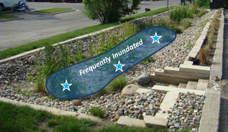
|7

                               FIELD OBSERVATION PROTOCOL

                              Constant Head Permeameter (CHP)

BMP RAM assessments utilize the accepted Constant Head Permeameter developed by the NRCS within the
Lake Tahoe Basin.

Objective: Measure saturated hydraulic conductivity (Ksat) of the base of a structural BMP.

BENCHMARK OBSERVATION

Benchmark observations should be made immediately following construction or complete maintenance
actions, when the structural BMP is in best achievable condition. Benchmark observations are made following
the field observation protocols detailed below.

FIELD OBSERVATION

Personnel Required: 1 field worker will require 20
minutes to make one measurement. Each structural
BMP will require a minimum of 3 measurements
depending upon size and the complexity of
topography of the structural BMP footprint.

Equipment Required:
    •  Constant Head Permeameter
    •  Spacer and spacer base
    •  Bore hole tool (1” diameter pipe sharpened
       internally on one end)
    •  Wood dowel or rebar cleaner rod
    •  Hammer
    •  1 gallon of water per measurement
    •  Stop watch
    •  Field datasheet, either hard copy or
       accessed on website through mobile device
    •  Map of structural BMP locations

Optimal time to perform: May 1- June 30th

A. Preparation
    •    Avoid making observations within 24hrs of
         most recent runoff event.
    •    Determine structural BMP footprint area from
         the inventory (ft2). Prior to making CHP
         measurement field observations field staff
         should conduct a general site assessment to
         determine the distribution of the structural BMP
         footprint     that   will     experience    different
         inundation frequencies. The surfaces at lower
         elevations will be inundated more frequently
         and have a greater rate of sediment and
         material accumulation. This characteristic will
         result in different infiltration rates in areas with
         different elevations. The goal of the CHP
         measurements is to complete 3 distinct
         measurements in both the frequently inundated
         and occasionally inundated areas. The table
         below summarizes the number of required
         measurements based on observed surface types

        500 Seabright Avenue, Suite 205 | Santa Cruz, CA 95062 | 2ndnaturewater.com | 831.426.9119
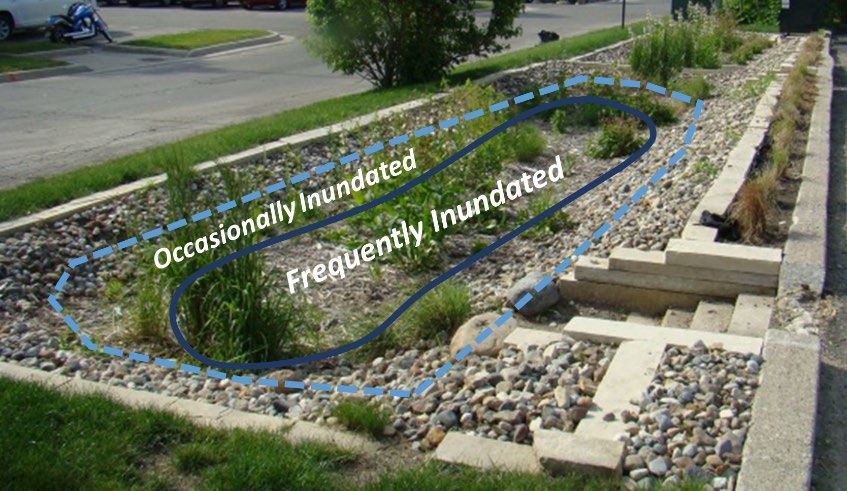
|8

         as defined by inundation frequency (see graphic for examples of inundation frequencies). Three
         measurements within both surface types allows verification of the Ksat expected by visual
         observation and relative inundation frequency.
     •   The most reliable CHP observations over time will be repeated in the same locations within each
         specific structural BMP. It is recommended that users create and maintain structural BMP specific
         maps on larger more centralized structural BMPs that require CHP BMP RAM observations to ensure
         that CHP measurement locations are repeated.
     •   2Nform recommends the number of measurement locations based on the asset’s footprint. Perform
         up to 3 measurements in the frequently inundated area. Should the recommended # of locations
         exceed 3, additional measurements can be made in the occasionally inundated area.

                The tool recommends the number of locations that infiltration measurements should be made,
                based on the asset’s footprint.

B.   Select measurement locations
     •   Visually determine the area of each distinct surface type within the footprint of the structural BMP.
         Within both the frequently inundated and occasionally inundated areas, distribute 3 required
         measurements per surface type throughout the structural BMP. The distinct surface types will
         collectively represent a range of the footprint characteristics of the structural BMP (i.e., some
         locations that are inundated during all smaller events and some locations that are only inundated
         during larger events).
     •   All measurement locations must be close to level.
     •   Location ID is for the user to keep track of CHP measurements if desired. A simple map of the
         locations of each measurement may be useful, though the map is for internal use only. The
         measurement location should be consecutive numbers starting at 0 and going to 6, representing the
         number of CHP measurement conducted at the structural BMP. Click “Save Record” to enter the
         measurement and click the X button to delete any mis-entered records.

            In benchmark form, user must specify “CHP” as the method. Enter location ID, start time, and
            water height to record infiltration measurements.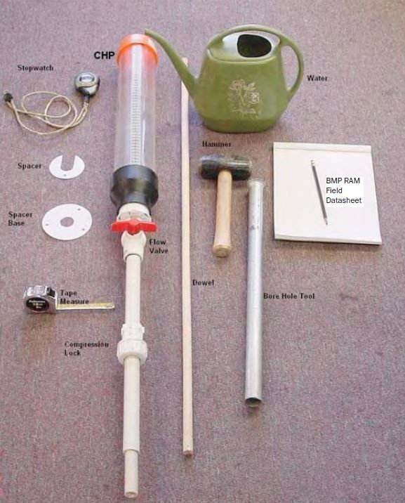
|9

C. Instrument setup
   •    Select location for measurement. The ground surface should be flat and free of debris.
   •    Record measurement location ID on field datasheet.
   •    Vertically hammer the bore hole tool into the ground to a depth of 4 inches.
   •    Gently remove the bore hole tool from the ground.
   •    Remove the soil from the bore hole tool with the dowel/rebar or by tapping the back of the tool on
        the ground or the hammer.
   •    Note: In very sandy, dry, or uncompacted soils, material may fall out of the bore hole tool and back
          into the measurement hole when the tool is extracted. If this happens, slowly apply ~½ liter of water
          to the measurement hole and allow it to infiltrate; this will make the sediment more cohesive. Use the
          bore hole tool to clean out the hole to a depth of 4 inches.
     •    Clean the soil debris away from the rim of the hole and place spacer base over the hole.
     •    Fill the CHP with water to the 175 mark. Do not over fill the CHP.
     •    Gently place the CHP tip through the hole in the spacer base, and slide in the spacer.

D.   Observation
     •  Slowly open the flow valve. Bubbles will enter the water storage chamber as water flows down
        through the insertion probe and displaces air. The water level within the storage chamber should
        stabilize within 30 seconds.
     •  Begin the stop watch after opening valve.
     •  Take the first reading at 2 minutes. This allows the surrounding soils to saturate during the first 2 minutes.
        Record location ID), time as minute (Time), and reading (Reading).
     •  Take a second reading in the middle of the infiltration process within 8 minutes and record. Be sure
        to use the same location ID.
     •  Take a third reading at 15 minutes and record. Be sure to use the same location ID.
     •  If it appears that the entire volume of water may drain during 15min, record the reading and time
        on an even minute prior to the water level reaching 0. It is not necessary to refill the tank to complete
        the 15-minute period.
                   i. When water infiltrates completely prior to the designated reading interval, take note of
                       the time when all water was infiltrated. Record the time, by rounding to the nearest ¼
                       minute (:00, :15, :30, :45) and enter as a decimal, record depth as 0 (Reading).

Troubleshooting
    •   If the CHP is losing water but no bubbles are observed in the chamber, air is coming in from the top.
        Reseal the cap.
    •   If small bubbles are observed, there may be leaking through the joints above or below the valve.
        This is common with new valves. If the small bubbles are accompanied by regular larger bubbles
        coming from the bore hole, the CHP is operating properly. This is because the Ksat of the soil is
        exceeding the minor air leak. To stop these small leaks try applying some silicone grease to both
        sides of the ball in the ball valve and reapply plumber’s tape to the threads in the joints and tighten
        until snug.
    •   No water flow is observed when the CHP valve is open. Likely the CHP chamber has been overfilled.
        Empty all water and refill to 175.
    •   If a reading is incorrectly entered, delete the entry from the table and re-enter.

         500 Seabright Avenue, Suite 205 | Santa Cruz, CA 95062 | 2ndnaturewater.com | 831.426.9119
|10
FIELD OBSERVATION PROTOCOL
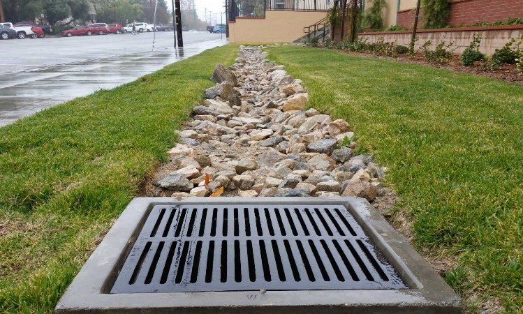
Conveyance
Objective: Visually determine if the BMP inlets, outlets, bypass structures or drop inlets are capable of
conveying stormwater as intended.
BENCHMARK OBSERVATION
No benchmark observations are necessary for this protocol.
FIELD OBSERVATION
Personnel Required: One field worker will require 3 minutes to make an observation at each BMP inlet, outlet,
bypass structure or drop inlet.
Equipment Required:
• Field datasheet, either hard copy or accessed on website through mobile device
• Map of structural BMP locations
Optimal time to perform: Not season dependent.
A. Preparation
• Avoid making observations within 24hrs of most recent runoff event.
B. Observations
• Has a runoff event occurred in the past 24 hours (yes/no)?
o If yes, return at time when answer is NO.
• Visually inspect each inlet structure. Does the inlet appear capable of delivering stormwater to the
structural BMP as intended (Yes/No)? The following are indications it is NOT functioning:
o The elevation of the inlet is higher than the
surrounding drainage area, preventing flow
into the BMP.
o The elevation of the inlet is below the BMP
surface, such that water may not get to or exit
the BMP through the inlet.
o The slope of the inlet is too shallow and
stormwater backflows from the structural BMP.
o Evidence of a flow path suggests water is
diverted around or away from the inlet
structure.
o Inlet culvert is clogged or crushed.
o Inlet pipe is separated, and water is seeping
out of culvert before entering BMP.
o Trash capture device is full of debris and
essentially clogged.|11
• Visually inspect each outlet structure. Does the outlet appear capable of delivering stormwater from
the structural BMP as intended (Yes/No)? The following are indications it is NOT functioning:
o In BMPs where ponding should occur,
the elevation of the outlet is too low to
allow sufficient ponding and flow
attenuation.
o Flow is being diverted around or away
from the outlet.
o Outlet culvert is clogged or crushed.
o Outlet pipe is separated, and water is
seeping out of culvert before entering
the stormwater conveyance system
as intended.
o Trash capture device is full of debris
and essentially clogged.
• Visually inspect each bypass structure. Does
the bypass structure appear capable of conveying stormwater around the structure BMP as
intended (Yes/No)? The following are indications it is NOT functioning:
o For bypass structures near inlets, the bypass invert elevation is below the inlet invert and
stormwater is diverted away from the structural BMP.
o For bypass outlet structures, bypass invert elevation is below the outlet invert and stormwater
short-circuits the primary flow path and treatment provided by the BMP.
o Bypass structure is clogged, crushed, or full of holes.
C. Next Steps
• If the answer for any inlet or outlet is NO, further evaluate the site to direct the proper actions to
improve the conveyance function at the structural BMP:
o Does the conveyance feature appear to require debris removal to restore intended
function?
o Does it appear that the conveyance feature may need to be replacement, re-plumbing, or
other more substantial improvement? Consider perceived issues including safety hazard
identified, liability to create flooding upstream identified, etc. in the notes section.
o Photograph any inlet or outlet that appears to need maintenance and/or replacement.
500 Seabright Avenue, Suite 205 | Santa Cruz, CA 95062 | 2ndnaturewater.com | 831.426.9119|12
FIELD OBSERVATION PROTOCOL
Infiltrometer
Objective: Quantitatively measure the infiltration rate of a structural BMP.
BENCHMARK OBSERVATION
Benchmark observations should be made immediately following construction or complete maintenance
actions, when the BMP is in best achievable condition. Benchmark observations are made following the field
observation protocols detailed below. User must select “Infiltrometer” as the method and conduct infiltration
tests at the recommended number of locations.
In benchmark and threshold form, user must specify the method as “infiltrometer”. The tool
recommends the number of locations that infiltration measurements should be made based on the
asset’s footprint.
FIELD OBSERVATION
Personnel Required: One field worker will require 10 minutes to conduct one infiltration measurement.
Observation will take 15 to 30 minutes per structural BMP depending upon the number of measurements
required.
Equipment Required:
• 2 gallons of water (per measurement)
• Double-ring infiltrometer
• Ruler or tape measure
• Rubber mallet
• Stop watch
• Field datasheet or mobile device
• Map of structural BMP locations
Optimal time to perform: May 1- June 30th|13
A. Preparation
• Avoid making observation within 24
hours of most recent runoff event.
• Prior to making infiltrometer
measurements, field observations
should be conducted to determine the
distribution of the structural BMP
footprint that will experience different
inundation frequencies. The surfaces at
lower elevations will be inundated
more frequently and have a greater
rate of sediment and material
accumulation (see graphic for
examples of inundation frequencies).
This characteristic will result in different
infiltration rates in areas with different elevations. The goal of the infiltrometer measurements is to
complete distinct measurements in both the frequently inundated and occasionally inundated
areas.
• 2Nform automatically recommends the number of measurement locations based on the asset’s
footprint. Perform up to 3 measurements in the frequently inundated area. Should the
recommended # of locations exceed 3, additional measurements can be made in the occasionally
inundated area.
B. Select Measurement Locations
• Divide the structural BMP into equal sections based on the number of recommended measurements.
• Location ID is for the user to keep track of infiltrometer measurements. A simple map of the locations
of each measurement may be useful, though the map is not required and is for internal use only. The
measurement location should be consecutive numbers starting at 0.
• It is not necessary for the user to repeat measurements in the exact location during each subsequent
field observation.
C. Instrument Setup
• Find a flat surface in the area to be tested.
• Insert infiltrometer into the soil by pushing down on the
handle while twisting the instrument back and forth
until the rings are inserted deep enough to prevent
water from escaping (~1”).
• If harder soils are being tested, use a driving plate
to cover the infiltrometer and rubber mallet to
pound the plate and insert the rings into the
ground.
• If using an infiltrometer on gravel surface,
excavate gravel where rings will be inserted and
push and twist the instrument into place.
• Tamp down the disturbed soil, or replace excavated
gravel, adjacent to the ring on the inside of the outer
ring and both sides of the inner ring to ensure a seal.
• Set ruler inside the inner ring to monitor water depth.
D. Observation
• Fill both the inner and outer rings with water (roughly 1 – 2 gallons of water). Add enough water so
the water level is even to start between the inner and outer rings.
• Begin the stopwatch and measure the height of water (in inches) in the inner ring using the ruler.
• Record the Observed Measurements (assign each observation a Location ID number), start time as
0 (Minutes), and reading as water height (Reading; in inches).
• Click the “Save Record” button to save data entry and move on to the next line entry.
500 Seabright Avenue, Suite 205 | Santa Cruz, CA 95062 | 2ndnaturewater.com | 831.426.9119|14
• At 2 minutes, record the Location ID, time as 2 minutes, and measure and record the water level in
the inner ring (Reading; in inches). Note: water level measurements can be entered to the
hundredths of an inch.
• Click the “Save Record” button to save data and move on to the next line entry.
• Take a third reading at 5 minutes and record ID, Minutes and Reading (inches).
o If the water infiltrates completely prior to the 2-minute or 5-minute reading, take note of
the time when all water was infiltrated. Record the time, by rounding to the nearest ¼
minute (:00, :15, :30, :45) and enter as a decimal (0.00, 0.25, 0.50, 0.75), record depth as
0 (Reading; in inches).
Round to nearest ¼ minute.
Click X to delete entry.
Round to nearest hundredth inch
For field observations, measure and record water depth (in inches) in the inner ring at minute 0, 2, and 5. If water in the inner
ring all infiltrates prior to a designated time interval, round time to the nearest ¼ minute and record ‘reading’ as 0. Infiltration
rates for each observed measurement will be automatically calculated in BMP RAM.
• Gently extract the infiltrometer from the soil.
• Repeat instrument set up and observation at the next measurement location.
• If a reading is incorrectly entered, delete the entry from the table (X) and re-enter.
Infiltration rates will be calculated in BMP RAM as inch per hour based on time and reading entries at each
location.|15
FIELD OBSERVATION PROTOCOL
Material Accumulation – Staff Plate
Objective: Determine the level of material accumulated within a structural BMP using permanent staff plates
installed within the structural BMP.
BENCHMARK OBSERVATION
Benchmark observations should be made immediately following construction or complete maintenance
actions, when the BMP is in best achievable condition.
Personnel Required: One to two field workers will require 15-30
minutes to install one staff plate within the structural BMP.
Equipment Required:
• Metal staff plate similar to Ben Meadows Product
#113470 in tenths of feet.
• Cement screw, wood screws or nails
• Power drill
• Saw
• 2x4 wood post
• Rebar or fence posts
• Fence post driver or mallet
• Hose clamps
• Permanent marker or paint
• Stadia rod or tape measure
A. Installation
Note: For BMPs where the user is not authorized to install, or installation is not feasible, please reference field
protocols for - Material Accumulation – Stadia Rod.
• 2Nform automatically recommends the number of measurement locations based on the asset’s
footprint.
• If base of structural BMP cannot be penetrated:
o Mount staff plate to vertical wall of structural BMP using cement screws and a power drill.
• If base of the structural BMP can be penetrated:
o Cut the corners of one end of a 2x4 to create a point for insertion into ground.
o Mount the staff plate to the 2x4 using nails or screws. The zero (0) on the staff plate should
be mounted 6” from the bottom of the 2x4. The top of the staff plate does not need to
extend vertically above the maximum water quality depth of the structural BMP.
o Using a fence post driver or mallet, drive the fence posts vertically into the base of the BMP
as far as possible to provide support.
o Drive the staff plate vertically between the two fence posts, aligning the zero (0) with the
base of the structural BMP. The fence posts should be on either side of the staff plate to
provide support.
o Attach staff plate with hose clamps.
• Write the ID on the staff plate either with paint, permanent marking or engraving into the 2x4 for
simple reference by the field personnel in the future.
B. Data Entry
• For each staff plate installed, select Type as “Staff Plate”, enter a brief description under Location,
the bottom-most value that can be read on the staff plate as Depth, and the units of measurement.
500 Seabright Avenue, Suite 205 | Santa Cruz, CA 95062 | 2ndnaturewater.com | 831.426.9119|16
• Click “Save Record.”
The tool recommends the # of locations where a staff plate is needed. For staff plate
installations, the user must select Staff Plate under the Type dropdown. User also will determine
the units used to perform field measurements.
FIELD OBSERVATION
Personnel Required: One field worker will require 5 – 10 minutes to make observation, with 1 – 3 measurements
required per structural BMP depending on the number of staff plates installed.
Equipment Required:
• Installed permanent staff plate
• Field datasheet or mobile device
• Map of structural BMP locations
Optimal time of year to perform: Not season dependent, but avoid completing when standing water is
present, if possible.
A. Preparation
• Avoid making observations within 24hrs of most recent runoff event.
B. Observations
• Locate the structure’s staff plate(s).
• Record the lowest value visible on the staff plate as Depth for each staff plate.
During field assessments, the user only enters the depth. The type, location, and units cannot be edited
from the information entered at the benchmark.|17
FIELD OBSERVATION PROTOCOL
Material Accumulation – Stadia Rod
Objective: Rapidly determine the material accumulated within a structural BMP using a stadia rod or tape
measure.
BENCHMARK OBSERVATION
Benchmark observations should be made immediately following construction or complete maintenance
actions, when the BMP is in best achievable condition.
Personnel Required: One to two field workers will require 5-10 minutes to identify measurement locations and
conduct initial depth measurement.
Equipment Required:
• Tape measure/ stadia rod / ruler
• Level or hand-held sight level (bioretention/biofiltration)
• Halogen Flashlight (confined/closed spaces)
• Field datasheet or mobile device
• Map of structural BMP locations
Optimal time to perform: Any, observation is not season dependent.
A. Measurement Locations
• 2Nform automatically recommends the number of measurement locations based on the asset’s
footprint.
• For structural BMPs with closed space field protocols:
o There are a variety of proprietary systems available that treat stormwater. Treatment vaults
are an example of proprietary BMPs with closed space. BMP RAM users should not enter
confined space for any reason. Each manufacturer has specific installation specifications
and maintenance recommendations. The BMP RAM user must determine the specific
configuration of the system and associated access ports in order to perform the appropriate
material accumulation field observations.
Underground structural BMPs vary greatly in
their individual design characteristics, but all
have one or more chambers where floatables
and sediment accumulate.
o Consult available documentation provided by
the manufacturer to locate access points
(manholes) where vertical measurements to
the structure’s bottom can be made with
stadia rod. Identify as many access chambers
as possible to improve the spatial distribution of
material accumulation estimates. In most
configurations, a maximum of 5 discrete
measurements is adequate. The measurement
locations should be verified in the field.
o Each access port (i.e., manhole) should be identified with an ID to distinguish it and ensure
it can be relocated by the field personnel during each subsequent BMP RAM field
observation.
o Write the ID on the manhole or on the cement nearby with spray paint for reference in the
future. Note locations of each access point in field notebook, drawing a sketch of site.
• For open air centralized BMP:
o Identify a fixed structure or element that is easily accessible and where field staff can return
in future years to make a measurement. Examples include top of an inlet culvert, top of
headwall; etc. It is important to select a fixed point that is several feet above the ground
500 Seabright Avenue, Suite 205 | Santa Cruz, CA 95062 | 2ndnaturewater.com | 831.426.9119|18
surface to provide a stable location from which vertical depth measurements can be made
for subsequent years.
o Write the ID on fixed structure and take detailed notes of its location and how to return to it.
• For decentralized BMPs:
o Locate where outflow occurs. Often the outlet is just the top of vertical corrugated metal
pipe, a raised grate, or sump at the down gradient edge. If there are multiple outlets, each
outlet should be considered a unique measurement location.
o Identify each outlet with a simple ID to ensure it can be relocated by field personnel during
subsequent field observations.
o Write the ID on the outlet or on the cement nearby with spray paint for reference in the
future.
B. Observations
• When the structural BMP is known to be free of debris (following installation and/or recent
maintenance) measure the depth:
o Treatment Vaults: from the bottom of the clean vault to top of the manhole used for access
for each measurement location.
o Open air centralized BMPs: measure the vertical distance from the ground surface equal to
the top of the fixed structure. Perform measurements at noted horizontal distance from the
fixed point, so that field staff can return to the same location for future measurements.
o Bioretention/Biofiltration: from the lowest point of the ponding surface to the invert of the
outlet structure.
o Sediment Trap: from the bottom of the clean BMP to the lowest elevation at which water
can flow out of the BMP.
• For each identified measurement location, enter a brief description for the measurement location,
the total depth measured, and the measurement units.
The tool recommends the # of locations where a stadia rod measurement is needed. The
user must select Stadia Rod under the Type dropdown. User also will determine the units
used to perform field measurements.
FIELD OBSERVATION
Personnel Required: One to two field workers will require 10-15 minutes to conduct observation, depending
upon the number of measurements required.
Equipment Required:
• Tape measure/ stadia rod / ruler
• Level or hand-held sight level (bioretention/biofiltration)
• Halogen Flashlight (closed spaces)
• Field datasheet, either hard copy or accessed on website through mobile device
• Map of structural BMP locations
Optimal time to perform: Any, observation is not season dependent.
A. Preparation
• Avoid making observation within 24hrs of most recent runoff event.
• Arrive at structural BMPs and locate measurement locations. Identify and verify each measurement
location and ID.|19
B. Observation
• Measure the material accumulation of the structural BMP:
o Closed Spaces: Measure and record the vertical distance between the bottom of the
system and the top manhole using a stadia rod or tape measure.
o Bioretention/Biofiltration: Locate the ponding area within the structural BMP and identify the
deepest location. Measure the vertical distance from the deepest spot to the invert of the
outlet structure (as illustrated in yellow in the schematic above). In some cases, the ponding
area may be some distance from the outlet structure. Material accumulation with a stadia
rod measures the vertical ponding depth at the deepest point and can be measured in 2
ways:
• Use a tape measure and ruler. One
field crew member pulls a tape
measure level from the outlet to the
deepest point. The second field
staff uses a ruler or a second tape
measure to determine the vertical
ponding depth.
• Utilize a handheld sight level tool
and a stadia rod to determine an
accurate ponding depth. Sight
levels can be used to calculate
depth in multiple ways. Use
preferred method or follow the
example below.
o Have one field crew member hold a stadia rod at
a point in between the outlet and the lowest ponding
depth. The other field crew member uses the handheld
sight level to make 2 separate height readings on the
stadia rod – one from the outlet structure looking towards
the deepest part (A) and another standing in the
deepest part looking towards the outlet (B). Calculate
the difference in stadia rod readings. This difference is the
remaining capacity of the BMP.
• Sediment Trap: Measure the vertical distance
between the lowest elevation at which water can flow
out of the BMP and the top of the material accumulated
within it.
500 Seabright Avenue, Suite 205 | Santa Cruz, CA 95062 | 2ndnaturewater.com | 831.426.9119|20
o In order to measure the amount of material accumulated, be careful not to force the
measuring tool into accumulated debris.
o Record depth to the nearest hundredth (Depth).
o Repeat for all established measurement locations.
During field assessments, the user only enters the depth. The type, location, and units cannot
be edited from the information entered at the benchmark.|21
FIELD OBSERVATION PROTOCOL
Permeability
Objective: Qualitatively estimate the degree to which a surface can rapidly infiltrate stormwater.
BENCHMARK OBSERVATION
No benchmark observations are necessary for this protocol.
FIELD OBSERVATION
Personnel Required: One field worker will require 10-15 minutes to conduct
observation, depending upon the number of measurements required.
Equipment Required:
• Field datasheet or mobile device
• Map of structural BMP locations
• Water
• 1L Graduated cylinder or bottle with volume markings
• Stopwatch
• Ruler/tape measure
• For pervious pavement:
24-oz metal can (typical
canned vegetable container)
with 4” diameter with top and
bottom removed
Plumber’s putty
• For bioretention, bioswale, biofiltration,
and infiltration feature:
24-oz metal can (typical
canned vegetable container)
with 4” diameter with top and
bottom removed
Rubber mallet
Optimal time to perform: May 1st – June 30th.
A. Preparation and Observation Locations
• Avoid making observation within 24hrs of most recent runoff event.
• Infiltration ability of a structural BMP can vary spatially based on BMP design, maintenance actions,
etc. To improve the consistency of the observation results across users, upon arrival to the site the
user should walk the entire boundary of the structural BMP and visually determine structural BMP
inundation regime boundaries. Visually identify areas within the primary stormwater flow path that
are frequently inundated (BMP inlet, outlet, and topographic lows where water collects during
smaller sized events) and those at a slightly higher elevation that are occasionally inundated during
larger volume runoff events. Note: pervious pavement often does not have an obvious primary flow
path, see instructions below.
500 Seabright Avenue, Suite 205 | Santa Cruz, CA 95062 | 2ndnaturewater.com | 831.426.9119|22
• 2Nform automatically recommends the number of measurement locations based on the asset’s
footprint. Perform up to 3 measurements in the frequently inundated area. Should the
recommended # of locations exceed 3, additional measurements can be made in the occasionally
inundated area.
B. Observation
• Select the observation method. There are different runoff methods
depending on the BMP surface:
o Pervious Pavement/Pavers: Secure the bottom of the 4” diameter
can to the pavement surface using the plumber’s putty. At paver
surfaces, secure the can over an intersection of permeable cracks.
Ensure a watertight seal is formed around the entire edge of the
can. Best performance occurs when the putty is on both the inside
and outside of the can.
o Concrete grid pavers (CGP): Secure metal
can in the pervious square space. If the
pervious space is too narrow to fit the metal
can, use plumber’s putty to form a watertight
seal between the can and concrete around
the pervious surface (see photo).
o Gravel or smaller substrate: For structural
BMPs where the main flow path substrate is
gravel or smaller, insert the metal can
approximately ½” into the substrate. Use the
rubber mallet as necessary to ensure an appropriate seal
between the can and substrate.
o Cobble or larger substrate: For structural BMPs where the
main flow path surface is cobble or larger, select an
embedded cobble that is approximately 4” in diameter
and remove it from the substrate. The remaining
depression should be approximately 2.5” deep and will
form a surface for adding water.
• Fill the graduated cylinder (or similar) with 400ml of water.
• Pour the 400ml into the can or depression in less than 5 seconds.
Note, if the depression cannot contain the 400ml, fill the available depression or crack with
appropriate water and keep adding as water is infiltrated until the total volume has been poured.
• Start the stopwatch as soon as the pouring begins.
• Stop the stopwatch when all the water has infiltrated or after 10 minutes, whichever is shorter in
duration.
• Record the number of minutes and seconds under Time.
• If the water did not fully infiltrate within 10 minutes, record the height or the remaining water in inches.
• Click “Save Record” button to save data entry and move on to the next line entry.
• Repeat above steps for all permeability measurement locations.
o NOTE: all permeability measurements performed at the BMP should be entered in the
same data form. By clicking “Save Record”, a new data entry line appears to record
another permeability timed observation. BMP RAM will average all permeability times
entered to incorporate into the score.
• If data is mis-entered, delete the observation from the table (X) and enter again.|23
Permeability observations that take > 10 minutes will
require height measurement of remaining water (in)
Water height
Click X to delete entry if
necessary
For field observations, record the time it takes to infiltrate 400 mL of water as minutes and seconds. All permeability
observations performed at one BMP should be entered in the sam e data form. Permeability rates for each test will be
averaged in BMP RAM and the average time will be incorporated into the score.
500 Seabright Avenue, Suite 205 | Santa Cruz, CA 95062 | 2ndnaturewater.com | 831.426.9119|24
FIELD OBSERVATION PROTOCOL
Standing Water- Closed Space BMPs
Some structural BMPs are constructed underground, or require entry through manholes, limiting access to
make standard field observations. BMP RAM field personnel are not certified to enter closed spaces to
perform assessments or make observations. Some closed space structural BMPs have observation ports to
inspect standing water or material accumulation. Qualitative observations can be made by field personnel
when observation ports exist. Instances where observation ports do not exist, or field personnel cannot access
or see into the BMP whatsoever, are classified as “Inaccessible” and must be maintained on recommended
maintenance interval specified by the manufacturer.
This closed space protocol provides the user with the proper steps to inventory and assess inaccessible closed
spaces and closed spaces with visual ports.
Objective: Determine the presence/absence of standing water in the closed space.
INVENTORY
Fill out all relevant general information about the BMP. Indicate the BMP’s System Accessibility is closed
space. In the “Closed Space Information” section, determine whether the BMP possesses observation ports
for standing water and/or material accumulation. If the BMP does possess observation ports for standing
water and/or material accumulation, select “Yes.” If it doesn’t possess any observation ports, select “No.”
Enter the recommended maintenance interval for the BMP.
BENCHMARK OBSERVATION @ OBSERVATION PORTS
No benchmark observations are necessary for Standing Water in Closed Space BMPs.
Note: If the Closed Space BMP also has an observation port for material accumulation, material
accumulation benchmark data is required. See the material accumulation protocol for more details.|25
FIELD OBSERVATION @ OBSERVATION PORTS
Personnel Required: One field worker will require 10 minutes to make visual assessment.
Equipment Required:
• Halogen Flashlight
• Stadia rod and/or long wooden dowel
• Field datasheet or mobile device
• Map of structural BMP locations
Optimal time to perform: Not season dependent but recommended from May 1 – June 30th.
A. Preparation
• Avoid making observations within 24hrs of most recent runoff event.
B. Observations
• Has a runoff event occurred in the past 24 hrs (yes/no)?
o If yes, return at time when answer is NO.
• Open the access observation port to inspect for standing water.
• Visually inspect each observation port. Does the structure have standing water on the floor? If yes,
return 24 hours later to inspect again and if standing water still exist (yes/no).
500 Seabright Avenue, Suite 205 | Santa Cruz, CA 95062 | 2ndnaturewater.com | 831.426.9119|26
FIELD OBSERVATION PROTOCOL
Substrate Type
Objective: Qualitatively estimate the biogeochemical cycling capacity of the substrate material of the
structural BMP.
BENCHMARK OBSERVATION
No benchmark observations are necessary for this protocol.
FIELD OBSERVATION
Personnel Required: One field worker will require 10-15 minutes to conduct observation.
Equipment Required:
• Field datasheet or mobile device
• Map of structural BMP locations
• Hand trowel
• Water
• Towel
Optimal time to perform: Any, observation is not season dependent.
A. Preparation
• Upon arrival to the site the user should walk
the entire boundary of the structural BMP
and visually determine structural BMP
inundation regime boundaries. Visually
identify areas within the primary stormwater
flow path that are frequently inundated
(BMP inlet, outlet, and topographic lows
where water collects during smaller sized
events).
• Divide the area of frequent inundation into
equal thirds along the primary flow path,
where the first third is closest to the inlet and
the last third is closest to the outlet.
• It is not necessary for user to repeat exact
measurement location during each
subsequent field observation.
B. Observation
• Within each third of the BMP, select a location within the primary flow path to collect a sample.
• Use the hand trowel to remove any surface layer material (mulch, pea gravel, vegetation debris) to
investigate the top 6 inches of the substrate material.
• Determine the primary substrate with the highest distribution at the location as:
o Bioretention soil – uncompacted, soft, organic material that is easy to dig and crumbles
in hand.
o Coarse material – larger-sized cobbles, gravel, pea gravel or coarse sand with minimal
organic content.|27
o Inorganic sand – smaller size material that is easy to dig, easily sifts through fingers.
Regular, uncompacted dirt with little organic material is considered functionally
equivalent to inorganic sand and should be classified accordingly.
o Clay compacted soil – fine grained, dense material that is hard to dig. If water is added
to this material, you can easily roll between your hands to create a ‘worm’.
• If more than one substrate material is present, determine the substrate type with the second
highest distribution from the four options.
• For each location, use the drop-down list to select the primary and secondary (if present)
substrate types.
• If the user is unsure of which substrate to select, follow the soil texture flowchart on the following
page (Modified from S.J. Thien. 1979. A flow diagram for teaching texture by feel
analysis. Journal of Agronomic Education. 8:54-55).
• Once the texture is determined, enter the correct substrate type in BMP RAM.
Make sure that both the primary and secondary types are
selected for all 3 locations (it can be the same type).
500 Seabright Avenue, Suite 205 | Santa Cruz, CA 95062 | 2ndnaturewater.com | 831.426.9119|28
|29

                            FIELD OBSERVATION PROTOCOL

                                            Vegetation Cover

Objective: Qualitatively estimate the relative density of each type of vegetative present within a structural
BMP.

BENCHMARK OBSERVATION

No benchmark observations are necessary for this protocol. Benchmark values are set as default values
based on typical design standards by structural BMP type. Review the table below for default benchmark
values.

Default benchmark values can be changed if BMP design plans or other local knowledge indicates different
standards for vegetation cover.

                                  BMP Type           Benchmark       Threshold

                                  Dry Basin             0%              20%

                                  Wet Basin             75%             40%

                               Infiltration Basin       0%              20%

                                   Bioswale            100%             80%

                              Infiltration Feature      0%              20%

FIELD OBSERVATION

Personnel Required: One field worker will require 10-15 minutes to conduct observation, depending upon the
number of measurements required.

Equipment Required:
    •  Field datasheet or mobile device
    •  Map of structural BMP locations

Optimal time to perform: May 1st -June 30th.

A. Preparation
   •   Qualitative estimates of % cover can be
       difficult and subject to user discretion. To
       improve      the   consistency     of    the
       observation results across users, the user
       should walk the perimeter of the structural
       BMP and visually determine structural BMP
       inundation regime boundaries. Visually
       identify    areas   within    the   primary
       stormwater flow path that are frequently
       inundated (BMP inlet, outlet, and
       topographic lows where water collects during smaller sized events). Then locate and evaluate the
       areas that are at a slightly higher elevation and are occasionally inundated during larger volume
       runoff events. Assess the vegetation within the area of these two inundation regimes (frequently and
       occasionally inundated).

      500 Seabright Avenue, Suite 205 | Santa Cruz, CA 95062 | 2ndnaturewater.com | 831.426.9119
|30
• Users should review and become familiar with potential examples of the 3 different vegetation types:
wetland/riparian species, trees, and grasses.
• Do not consider the vegetation cover that is rooted at an elevation higher than the top of the
structural BMP outlet.
B. Observation
• For each vegetation type, estimate the % cover within the structural BMP surface area that is within
the frequently and occasionally inundated areas. Enter this estimate to the nearest integer.
• The percent cover of bare soil estimate is automatically calculated by the tool.
• The BMP type will dictate which vegetation types affect its condition score. For example, at some
structures, such as infiltration features, grass can help with infiltration, because it opens pore spaces
for water to drain into the subsurface. Users will enter the percent cover by species type, and
condition scores are calculated based on vegetation that could impact the feature’s optimal
functionality. For example, an infiltration feature with 50% grass and 50% wetland species, only the
50% wetland species will affect its condition score. See table below for condition score breakdown.
(Note: even if a specific vegetation type doesn’t affect the score, it should still be recorded during
field observation).
Vegetation Type That Affects Score
BMP Type Wetland/Riparian Grass Trees
Dry Basin x
Wet Basin x
Infiltration Basin x
Bioswale x x
Infiltration
x x
FeatureYou can also read