Verification of visual odometry algorithms with an OpenGL-based software tool
←
→
Page content transcription
If your browser does not render page correctly, please read the page content below
Verification of visual odometry
                 algorithms with an OpenGL-based
                 software tool

                 Piotr Skulimowski
                 Pawel Strumillo

Downloaded From: https://www.spiedigitallibrary.org/journals/Journal-of-Electronic-Imaging on 11 Sep 2021
Terms of Use: https://www.spiedigitallibrary.org/terms-of-use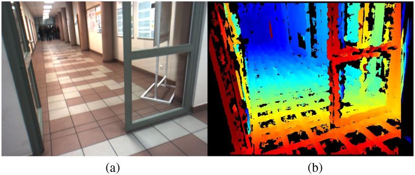
Journal of Electronic Imaging 24(3), 033003 (May∕Jun 2015)

                Verification of visual odometry algorithms
                with an OpenGL-based software tool
                Piotr Skulimowski* and Pawel Strumillo
                Lodz University of Technology, Institute of Electronics, 211/215 Wolczanska Street, Lodz 90-924, Poland

                              Abstract. We present a software tool called a stereovision egomotion sequence generator that was developed
                              for testing visual odometry (VO) algorithms. Various approaches to single and multicamera VO algorithms are
                              reviewed first, and then a reference VO algorithm that has served to demonstrate the program’s features is
                              described. The program offers simple tools for defining virtual static three-dimensional scenes and arbitrary
                              six degrees of freedom motion paths within such scenes and output sequences of stereovision images, disparity
                              ground-truth maps, and segmented scene images. A simple script language is proposed that simplifies tests of
                              VO algorithms for user-defined scenarios. The program’s capabilities are demonstrated by testing a reference
                              VO technique that employs stereoscopy and feature tracking. © The Authors. Published by SPIE under a Creative
                              Commons Attribution 3.0 Unported License. Distribution or reproduction of this work in whole or in part requires full attribution of
                              the original publication, including its DOI. [DOI: 10.1117/1.JEI.24.3.033003]

                              Keywords: stereovision; OpenGL; egomotion estimation; visual odometry; passive navigation.
                              Paper 14751 received Nov. 26, 2014; accepted for publication Apr. 13, 2015; published online May 7, 2015.

                1 Introduction                                                                      motions devoid of translational movements. On the other
                Motion parameters of an object (further termed egomotion                            hand, in Ref. 19, a method based on optical flow for estimat-
                parameters) are given by a set of kinematic quantities defin-                       ing only the translational motion vector was proposed. In
                ing the object’s movement in relation to its environment.                           Ref. 20, a special, omnidirectional camera for maximizing
                Robust estimation of egomotion parameters is an important                           the field of view (FOV) was used, which allowed a more
                problem in robotics, automatic navigation, and computer                             flexible choice of the tracked keypoints. An algorithm for
                vision systems.1 Egomotion parameters are essential in                              estimating six degrees of freedom (6 DoF) motion vector
                planning movement paths in obstacle avoidance systems,2                             was proposed in Ref. 13; however, the image scale informa-
                structure from motion methods,3,4 and in simultaneous locali-                       tion was derived from an altimeter.
                zation and mapping.5 Although there are various dead-reck-                              Most of the VO-based egomotion estimation algorithms
                oning techniques available for estimating egomotion                                 are dedicated to multi camera systems.6,7,21 These methods
                parameters, e.g., odometry, inertial, and laser sensing, the                        incorporate depth maps that allow for significant simplifica-
                vision-based techniques termed visual odometry (VO)6 are                            tion of computations involved in egomotion estimation. In
                continuously gaining in importance.7 This is because                                Ref. 21, to obtain an accurate global position and to achieve
                imaging sensors (including stereo imaging) offer passive                            robustness to motion blur, multilevel quadtrees and true scale
                data acquisition techniques that work in natural lighting con-                      scale-invariant feature transform descriptors were used. In
                ditions, and are inexpensive and are miniatured. Furthermore,                       Ref. 7, an iterative closest point algorithm was implemented
                efficient algorithms have been worked out for calibrating                           in real time for 6DoF egomotion estimation by tracking key-
                camera systems,8 tracking image objects,9,10 three-dimen-                           points detected by the Shi–Thomasi feature detector. In
                sional (3-D) scene reconstruction,11 and recognition.12                             Ref. 6, the RANSAC algorithm was used to estimate the
                Video imaging also becomes an important modality in multi-                          motion of a stereovision unit (720 × 240 pixels image reso-
                sensor navigation systems incorporating inertial sensors13                          lution and baseline 28 cm) mounted on an autonomous
                and the global positioning system.14                                                ground vehicle. Also, in Ref. 22, a stereovision system
                    VO systems can be divided into two major groups: single                         with a wider baseline (approximately 40 cm) was mounted
                camera systems (also termed monocular VO) and multica-                              on a vehicle and the employed algorithm allowed for estimat-
                mera systems.                                                                       ing the vehicle’s motion path in rough terrain.
                    Monocular VO algorithms primarily use feature tracking                              Although many efficient vision-based egomotion estima-
                methods. In Ref. 15, a 1-point-random sample consensus                              tion algorithms were developed (for single or multicamera
                (RANSAC) algorithm was employed for estimating vehicle                              systems), objective verification and comparison of their per-
                motion from single camera image sequences. In Ref. 16,                              formance is a difficult task. Building a robot-like device that
                real-time tracking of camera position is estimated by apply-                        would generate arbitrary 6DoF motion trajectories is expen-
                ing the particle filter combined with the unscented Kalman                          sive and would offer limited precision, repeatability, and
                filter. In Refs. 17 and 18, approaches to estimating rotation,                      range of movements. One possible solution for verification
                scale, and focal length parameters were presented for                               of egomotion estimation algorithms, as proposed in Refs. 15,
                                                                                                    21, and 23, is to use predefined image sequences. In Ref. 21,
                                                                                                    a sequence of 50 stereo frames was captured by a stereovi-
                *Address all correspondence to: Piotr Skulimowski, E-mail: pskul@p.lodz.pl          sion unit moving along a straight path. Location of the

                Journal of Electronic Imaging                                                033003-1                                    May∕Jun 2015   •   Vol. 24(3)

Downloaded From: https://www.spiedigitallibrary.org/journals/Journal-of-Electronic-Imaging on 11 Sep 2021
Terms of Use: https://www.spiedigitallibrary.org/terms-of-use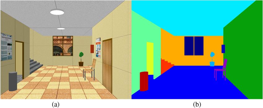
Skulimowski and Strumillo: Verification of visual odometry algorithms. . .

                system was advanced by 20 cm with each image recording.                             scenes that facilitate computation of egomotion parameters
                The accuracy of the system was verified by comparing con-                           of a moving camera system. In computational stereo, two
                secutive locations that were estimated by VO techniques to                          or more planar projections are recorded and the obtained
                ground-truth values. The obvious shortcoming of such a veri-                        images are compared to reconstruct 3-D scene geometry.
                fication method is the path shape that is constrained to line                       Due to the difficulties in precise alignment of relative orien-
                segments. In Ref. 15, vehicle movement in virtual urban ter-                        tations of the cameras and the limited precision of their
                rain is simulated to test the RANSAC-based structure from                           optics, the scene reconstruction task needs to be preceded
                motion algorithms. Facades of buildings were modeled by                             by appropriate camera calibration procedures, see Ref. 27.
                surfaces spanned on 1600 uniformly scattered keypoints.                             Once internal camera geometries are corrected and external
                Image sequences of the simulated scene were captured by                             geometries rectified, the stereovision system is termed to be
                rotating a stereovision system with one camera located at                           calibrated.27
                the center of rotation. Again, the movement path of the sys-                            For a calibrated, nonverged two-camera system, a scene
                tem is limited to a simple rotational motion. In Ref. 23, a                         point PðX; Y; ZÞ placed within the FoVof the cameras is pro-
                method for detecting objects in stereoscopic images of                              jected onto image points pL ðxL ; yÞ and pr ðx; yÞ in the left
                scenes was proposed. For testing the accuracy of the algo-                          and right cameras correspondingly. Note that y coordinates
                rithm, a 600-frame simulated image sequence of an urban                             of the scan lines of these two points are the same for a cali-
                scene was rendered and the corresponding ground-truth dis-                          brated stereovision system. Hence, the depth of a scene point
                parity maps were generated.                                                         P can be estimated from the shift d ¼ xL − x termed dispar-
                    There have also been special image databases built (see                         ity. If frontal pinhole camera models are adopted, origins of
                Ref. 24) that contain depth maps and the corresponding ster-                        the image coordinate systems oxy are located in image cen-
                eovison images; however, the number and type of imaged                              ters and the origin of the space coordinate system OXYZ is
                scenes are limited.25 Moreover, the offered databases contain                       positioned in the focal point of the right camera (see Fig. 1),
                a small number of short, few seconds long sequences of                              the relation between the coordinates of a space point
                image pairs, and they do not contain the ground-truth                               PðX; Y; ZÞ and the coordinates of its projection onto the
                depth maps and the segmented images.                                                right camera image plane is given by27
                    Although it is possible to generate synthetic data by using
                3-D modeling software, the resulting models are not suitable                                X            Y           Bf
                for direct and straightforward generation of the depth maps                         x¼f       ;   y¼f      ;   Z¼       ;                              (1)
                                                                                                            Z            Z            d
                and the segmented image. Such a procedure requires
                advanced programming skills from the user.                                          where f is the focal length of the camera, B is the baseline of
                    In this paper, a software tool for verification of VO algo-                     the stereovision system (i.e., distance between the cameras’
                rithms is proposed. The software enables generation of user-                        optical axis), and Z is the depth of point P.
                defined 3-D scenes with sequences of egomotion parameters                              Determining disparity for a given scene point is termed
                of a freely moving stereovision camera in custom defined                            the correspondence problem and it can be solved by applying
                scenes and recording of the corresponding stereoscopic                              various methods as reviewed in Ref. 11. From local methods,
                and ground-truth disparity maps. An additional feature of                           the block matching techniques are frequently used because
                the program is the availability of image sequences in                               they lend themselves well to parallel computations, e.g., on
                which the scene objects are segmented out and labeled,                              GPU platforms.28 By computing disparities for all imaged
                which allows testing the segmentation algorithms. The pro-                          scene points within the FOV, a so-called disparity map
                gram is written in C++ with the use of open graphics library                        can be obtained, see Fig. 2. Then the depth of scene points
                (OpenGL). The tool, that is made freely available on a web-                         can be directly computed from the right hand side of Eq. (1).
                page,26 features a simple interpreter for defining scene                            However, due to quantized values of disparities (for digital
                objects and the motion parameters of the user selected per-                         cameras), the corresponding depths are also quantized with a
                spective camera model. Our software tool enables the gen-                           resolution that decreases with increasing depths. Access to
                eration of much longer image sequences than the existing                            the ground-truth depth map allows for verification of the
                databases and contains the ground-truth maps and the corre-                         algorithms for computing the depth maps. It should be
                sponding segmentation images. Test sequences and scripts
                used for their generation are available from the webpage
                of the project.
                    The paper is organized as follows. In Sec. 2, a very brief
                introduction to stereovision is given. In Sec. 3, a basic algo-
                rithm for egomotion estimation from stereoscopic VO is pre-
                sented. This algorithm will serve as a reference method
                tested by the proposed software tool presented in Sec. 4,
                in which the main features of the developed program are
                described. In Sec. 5, the test results are outlined and
                Sec. 6 summarizes the advantages of the proposed software
                tool and its possible applications.

                2 Stereovision Basics
                                                                                                    Fig. 1 The OX Y Z frame of reference and the image coordinate sys-
                Viewing the environment from more than a single spatial                             tem ox y with the indicated translation motion parameters ðU; V ; W Þ
                location allows for recovering 3-D relationships of imaged                          and rotation motion parameters ðα; β; γÞ.

                Journal of Electronic Imaging                                              033003-2                                          May∕Jun 2015    •   Vol. 24(3)

Downloaded From: https://www.spiedigitallibrary.org/journals/Journal-of-Electronic-Imaging on 11 Sep 2021
Terms of Use: https://www.spiedigitallibrary.org/terms-of-use
Skulimowski and Strumillo: Verification of visual odometry algorithms. . .

                                       Fig. 2 (a) Image taken by the right camera of a stereovision system after compensation of geometric
                                       distortions and (b) the corresponding disparity map displayed in pseudocolors. Black regions denote
                                       areas of the map for which disparity could not be calculated with sufficient confidence.

                noted, however, that estimation of the precision of the depth                                X
                                                                                                             P
                map calculated for real scenes (e.g., as shown in Fig. 2) is, in                    E¼             ½ðui þ xi − xi0 Þ2 þ ðvi þ yi − yi0 Þ2 :                   (4)
                practice, impossible without the knowledge of the scene                                      i¼1
                model and precise coordinates of the cameras in that scene.
                                                                                                          By substituting appropriate expressions from Eqs. (1) and
                                                                                                    (2)
                3 Estimation of Egomotion Parameters from
                   Stereovision Sequences                                                                   a1i ¼ −f
                                                                                                                  Zi                a2i ¼ 0             a3i ¼ Zxii
                Consider a coordinate frame of reference OXYZ whose ori-
                gin is located at a focal point of the right camera of a stereo-                                                         x2i
                                                                                                            a4i ¼ xifyi        a5i ¼ − f þ f           a6i ¼ yi
                vision system (Fig. 1). Assume the system moves freely in a
                space in which there are no moving objects. Translational
                movement of the system in the defined coordinate frame                                  b1i ¼ 0                     b2i ¼ −f
                                                                                                                                          Zi            b3i ¼ Zyii
                is described by a vector of translation velocities ½U; V; W
                                                                                                            y2
                and a vector of angle velocities ½α; β; γ as shown in                              b4i ¼ fi þ f                  b5i ¼ − xifyi       b6i ¼ −xi
                Fig. 1. Hence, the system can be defined as a rigid object
                with 6DoF.
                   The objective is to estimate the motion parameters of the                        one gets
                stereovision system from the optical flow of the scene points
                                                                                                             X
                                                                                                             P
                projected onto the pair of images. Assume ½u; v denotes the                        E¼             ½ða1i U þ a3i W þ a4i α þ a5i β þ a6i γ þ xi − xi0 Þ2
                velocity vector of point pðx; yÞ in the right camera image.                                  i¼1
                The relationship between the velocity vector ½u; v and the
                system motion parameters is given by (see derivation in                                      þ ðb2i V þ b3i W þ b4i α þ b5i β þ b6i γ þ yi − yi0 Þ2 : (5)
                Refs. 4, 29, and 30)
                                                                                                       The following matrix equation is obtained after partial
                                                      2
                                                                                                   derivative equations with respect to the searched parameters
                   −Uf þ xW    xy     x
                u¼          þα −β        þ f þ γy;                                                  of the motion vector XT ¼ ½U; V; W; α; β; γ are evaluated
                      Z         f      f                                                            and equated to zero:
                                2
                   −Vf þ yW      y         xy
                v¼          þα     þ f − β − γx:                                        (2)         HX ¼ K;                                                                    (6)
                      Z          f          f

                   Assuming a sufficiently high video frame rate, the optical                       where elements hmn and km of matrices H6×6 and K6×1 are
                flow of image points can be assumed to be linear and                                defined as follows:
                approximated by the following difference equation:
                                                                                                                X
                                                                                                                P
                                                                                                    hmn ¼         ðami ani þ bmi bni Þ
                x 0 ¼ x þ u;       y 0 ¼ y þ v;                                         (3)                     i¼1

                where pðx; yÞ is a coordinate of point p at frame t and                                       X
                                                                                                              P
                ðx 0 ; y 0 Þ is the new coordinate of this point in frame t þ 1.                    km ¼        ½ami ðxi0 − xi Þ þ bmq ðyi0 − yi Þ:
                    By determining the optical flow for P (P ≥ 3) image                                        i¼1
                points, the six-element motion vector of the stereovision sys-
                tem can be computed by finding the minimum of the follow-                              Matrix Eq. (6) needs to be solved for X for each new
                ing cost equation:                                                                  incoming stereoscopic image frame.

                Journal of Electronic Imaging                                              033003-3                                                May∕Jun 2015      •   Vol. 24(3)

Downloaded From: https://www.spiedigitallibrary.org/journals/Journal-of-Electronic-Imaging on 11 Sep 2021
Terms of Use: https://www.spiedigitallibrary.org/terms-of-use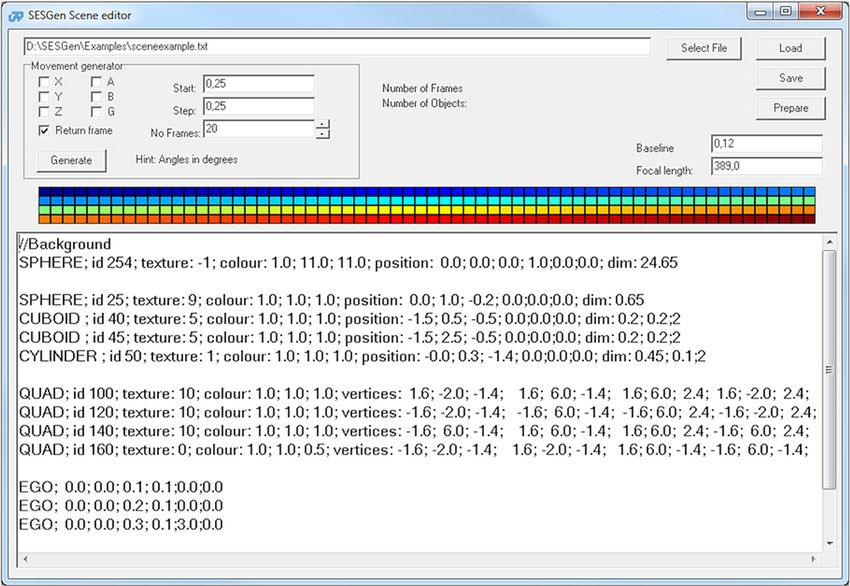
Skulimowski and Strumillo: Verification of visual odometry algorithms. . .

                3.1 Selection of Image Keypoints for Egomotion                                      4.1 Z-Buffer
                     Estimation                                                                     OpenGL is a universal programming library used for gener-
                Estimation of six egomotion parameters requires the deter-                          ating and rendering 2-D and 3-D scenes.34 The basic tools
                mination of the optical flows of at least P ¼ 3 image points                        used for generating 3-D graphics are the two buffers: the
                (further termed keypoints). However, for a robust estimation                        color buffer which stores an image array for display and
                of the egomotion parameters, the following conditions need                          the depth buffer (termed the Z-buffer) which stores each pix-
                to be fulfilled:                                                                    el’s depth.35 The Z-buffer stores the depth of a scene point
                                                                                                    from a pool of candidate scene points that has the smallest
                    • the keypoints should be selected according to the                             depth and picks it up for rendering. This process, termed
                      adopted stereo-matching algorithms, e.g., for the                             Z-culling, eliminates the need for rendering hidden scene
                      block methods the keypoints should correspond to cor-                         elements. If the depth values in the Z-buffer are stored
                      ners, edges, characteristic local color regions, or                           with N-bit precision, the depth is quantized to ½0; 2N − 1 lev-
                      textures;31                                                                   els. The values zb stored in the Z-buffer are related to
                    • the number of the tracked keypoints should be suffi-                          metric depth values Z of the scene points by the following
                      ciently large to minimize the quantization effect of                          equation:36,37
                      their coordinates;
                    • the depth of the keypoints should be computed with                                                    b
                                                                                                    zb ¼ ð2N − 1Þ · a þ        ;                                 (7)
                      sufficient precision (gross mistakes should be elimi-                                                 Z
                      nated), hence, due to a hyperbolic relation between
                      the disparity and depth [see Eq. (1)], the keypoints fea-                     where
                      turing a small depth are preferred.                                                        z Far
                                                                                                    a¼                     ;                                         (8)
                    The Shi–Tomashi algorithm, derived from the Harris                                      z Far − z Near
                detector32 and implemented in the OpenCV library, was
                applied for detecting the keypoints.33 For tracking the key-
                points in consecutive video frames, a full block search                                     z Far · z Near
                                                                                                    b¼                     ;                                         (9)
                matching method, similar to the one used in MPEG compres-                                   z Near − z Far
                sion standard, was used. The optical flow ½u; v of a given
                keypoint is thus determined by searching for a coordinate                           and z Near, z Far are the depths of the near and far clipping
                of a block of size M × M in current frame t þ 1 that best                           planes correspondingly. These clipping planes define the
                matches the block corresponding to a keypoint pðx; yÞ in                            scene depth range selected for rendering (see Fig. 4).34
                frame t. The minimum of the sum of absolute difference                                 Taking into account Eqs. (1) and (7), one can derive the
                (SAD) of the blocks’ pixels is used as the block matching                           following equation for disparity:
                criterion. In Fig. 3, a single video frame is shown with
                the highlighted optical flow vectors of the keypoints.                                           B · f · 2Nz−1
                                                                                                                             b
                                                                                                                               −a
                                                                                                         B·f
                                                                                                    d¼        ¼                      :                       (10)
                4 Generating Stereovision Sequences Using                                                 Z                b
                   OpenGL
                                                                                                       This value is defined as the subpixel disparity.
                Here, we propose a software tool for generating user-defined
                arbitrary motion paths that can be used for testing user VO
                algorithms. Because the tool employs OpenGL depth buffer-
                ing, a short introduction to its role in rendering 3-D scenes                       4.2 Program for Generating Stereovision Sequences
                is given.                                                                           The motivation for writing the program was the need to
                                                                                                    develop a tool for verifying visual odometry egomotion esti-
                                                                                                    mation algorithms. The proposed program allows the user to
                                                                                                    define a static 3-D scene and the movement path of the cam-
                                                                                                    era. For the defined movement trajectory in the defined scene,
                                                                                                    the program generates: sequences of 6DoF egomotion param-
                                                                                                    eters of the camera, corresponding stereovision images, and
                                                                                                    ground-truth disparity maps of the explored scene.
                                                                                                       The scenes can be built from quadrangles and three types
                                                                                                    of 3-D solid objects: cuboids, spheres, and cylinders. An

                Fig. 3 Scene image and optical flow vectors of the keypoints indi-                  Fig. 4 A viewing frustum defining the field and depth of view for a
                cated by white line segments.                                                       perspective camera model.

                Journal of Electronic Imaging                                              033003-4                                         May∕Jun 2015   •   Vol. 24(3)

Downloaded From: https://www.spiedigitallibrary.org/journals/Journal-of-Electronic-Imaging on 11 Sep 2021
Terms of Use: https://www.spiedigitallibrary.org/terms-of-use
Skulimowski and Strumillo: Verification of visual odometry algorithms. . .
object’s parameters, i.e., size, texture, color as well as its with disparity maps can also be downloaded from the
location and orientation can be defined by the user. website.
The program outputs the following data:
• a sequence of left and right camera images in Windows 4.3 Scene and Motion Description Language
bitmap format (bmp) with an option to corrupt the In order to facilitate building arbitrary 3-D scenes and defin-
images with an additive Gaussian noise of user-speci- ing 6DoF camera motions, a simple script language is pro-
fied standard deviation; posed. The scripts are stored as plain text, which allows for
• a sequence of disparity maps for the left and right cam- convenient editing and reusing of previously defined scripts
eras with pixel or subpixel accuracy; in new projects. The custom built script language features
keywords that define the following simple scene objects,
• a sequence of matrices containing disparity maps with
i.e., QUAD—quadrangle, CUBOID—cuboid, SPHERE—
16-bit resolution; sphere, and CYLINDER—cylinder. Each object keyword
• a sequence of segmented scene images. should be followed by a sequence of object properties.
For the quadrangles, the user should take care of defining
In Fig. 5, a flow diagram explaining the generation of data coordinates of the vertices to be coplanar. The keyword
sequences comprising camera motion vectors, stereovision EGO is used for defining frame-to-frame egomotion param-
images, depth, and segmentation maps is shown. First, the eters. Inserting comments into the script is possible by start-
scene model is built as defined by the user in the stereovision ing the script line with “//” (i.e., double slash). A graphical
egomotion sequence generator (SESGen) script. Then the user interface of a program designed for scene and egomo-
stereovision camera is moved in that scene along the path tion editing is shown in Fig. 7. The text window lists the
specified by a sequence of camera motion vectors. For script defining a 3-D scene shown in Fig. 6 and a sequence
each new camera position, left and right camera images of translation and rotation egomotion parameters individu-
are captured and the corresponding ground-truth depth ally defined for consecutive frames.
and segmentation maps are calculated and stored. The seg-
mented scene images are derived as follows. For each of the 5 Application of SESGen Software Tool for
defined scene objects, a disparity map is computed with Verifying Egomotion Estimation Algorithms
the object of interest being removed. Simple comparison from Visual Odometry
of the so obtained disparity map to a disparity map contain- In order to show the capabilities of the proposed SESGen
ing the scene object allows one to identify image regions cor- tool, an example 3-D scene and stereovision system egomo-
responding to the scene object under question. Then the tion path were defined by the script listed in Fig. 7. These
region corresponding to the rendered object is labeled data served as ground-truth reference for verifying scene
with a unique ID number which can be further used for reconstruction and egomotion estimation algorithms as
indexing a color from a predefined color palette [see an described in Sec. 3. The disparity maps were computed
example of a segmented scene image in Fig. 6(b)]. It is with pixel accuracy by applying a block matching method
worth noting that the disparity map is a reference map in which the SAD criterion was used.11 Depth values
obtained from the depth buffer, so that the disparity for were calculated from Eq. (1) for a predefined focal length
each point of the image is determined with subpixel accu- of the cameras and the baseline of the stereovision system.
racy. Note also that Eq. (2) includes translational and angular Estimation results of the egomotion parameters computed
velocities, whereas OpenGL methods define frame-by-frame by means of the visual odometry technique defined in Sec. 3
translational motions and rotations. In order to increase the are summarized in Table 1. The generated sequence consists
precision of the camera movement, the frame-to-frame of 40 stereovision images. The maximum absolute values for
motion is subdivided into an arbitrarily selected number each motion vector component are: U max ¼ 0.030,
of in-between frames (e.g., S ¼ 256). Code implementation V max ¼ 0.039, Zmax ¼ 0.044, αmax ¼ 0.8, βmax ¼ 0.8, and
of this procedure is explained in the SESGen user guide.26 γ max ¼ 0.5. The root-mean-square errors (RMSEs) for
The program was written in C++ using OpenGL and is made each of the estimated motion components are the following:
available free of charge on the website.26 Sample sequences RMSEX ¼ 0.0049, RMSEY ¼ 0.0101, RMSEZ ¼ 0.0062,
Fig. 5 Block diagram illustrating generation of motion vectors, images, depth, and segmentation maps in
the stereovision egomotion sequence generator (SESGen) software tool.
Journal of Electronic Imaging 033003-5 May∕Jun 2015 • Vol. 24(3)
Downloaded From: https://www.spiedigitallibrary.org/journals/Journal-of-Electronic-Imaging on 11 Sep 2021
Terms of Use: https://www.spiedigitallibrary.org/terms-of-useSkulimowski and Strumillo: Verification of visual odometry algorithms. . .
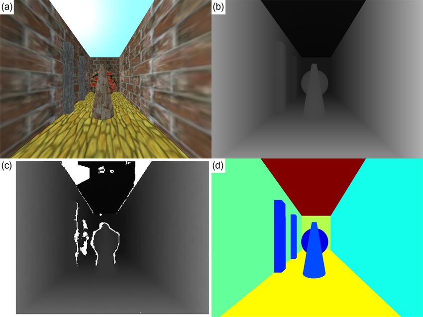
Fig. 6 A 3-D test scene defined by the script listed in Fig. 5: (a) 3-D test scene, (b) ground-truth disparity
map computed with subpixel accuracy, (c) disparity map obtained using sum of absolute difference
(SAD) (block matching) criterion, (d) scene segmented into 3-D objects and flat quadrangles positioned
in 3-D space.
Fig. 7 View of the program window for defining and editing three-dimensional (3-D) scenes and ego-
motion paths (see the SESGen User Guide26 for a complete explanation of the script keywords and
parameters).
Journal of Electronic Imaging 033003-6 May∕Jun 2015 • Vol. 24(3)
Downloaded From: https://www.spiedigitallibrary.org/journals/Journal-of-Electronic-Imaging on 11 Sep 2021
Terms of Use: https://www.spiedigitallibrary.org/terms-of-useSkulimowski and Strumillo: Verification of visual odometry algorithms. . .
Table 1 The ground-truth egomotion six degrees of freedom (6DoF) parameters and the estimated parameters obtained from the tested visual
odometry technique (distances are given in arbitrary OpenGL units and angles are given in degrees).
Ground-truth values Estimated values
Translational movement Rotational movement Translational movement Rotational movement
Frame number U V W α β γ U V W α β γ
1 0.020 0.020 0.025 −0.400 0.325 0.200 0.013 0.009 0.019 −0.197 0.327 0.157
2 0.023 0.011 0.026 −0.340 0.326 0.210 0.013 0.004 0.021 −0.184 0.277 0.144
3 0.025 0.017 0.027 −0.310 0.327 0.100 0.012 0.007 0.028 −0.137 0.268 0.014
4 0.020 0.021 0.028 −0.720 0.328 0.000 0.012 0.005 0.033 −0.482 0.325 0.114
5 0.023 0.000 0.029 −0.600 0.329 0.000 0.015 0.004 0.025 −0.486 0.291 0,054
6 0.020 0.000 0.030 −0.700 0.530 0.500 0.009 0.011 0.037 −0.502 0.489 0.444
RMSEα ¼ 0.101, RMSEβ ¼ 0.091, and RMSEγ ¼ 0.057,
where the distance RMSEs are given in arbitrary OpenGL
units and the angle RMSEs are given in degrees. The
ground-truth values are obtained from the SESGen software
tool. Note, however, that the table lists the egomotion param-
eters computed for six consecutive frames that were selected
from a longer sequence of camera movements as shown
in Fig. 8.
It was identified that the major contribution to egomotion
estimation inaccuracies comes from two sources. First, there
are errors in estimating motion vectors of the keypoints.
Second, errors occur due to calculations of the disparity val-
ues with pixel accuracy resulting in inaccurate estimation of
depth values for the keypoints. Plots of the defined motion
path and the estimated paths computed from the VO algo-
rithm are shown in Fig. 8. Note a successive diversion of
Fig. 8 Visualization of 3-D egomotion paths of the stereovision sys- path trajectories due to the incremental nature of the applied
tem: green dots (on the left) indicate a sequence of camera positions VO algorithm described in Sec. 3. Improvements on the
defined from the SESGen tool and the red dots (on the right) denote a results presented in Table 1 can be achieved by applying sub-
sequence of camera positions computed from the tested visual odom-
etry (VO) algorithm. pixel methods for computing the motion vectors of the key-
points in consecutive images.
Fig. 9 Example of a realistic scene with its segmentation map: (a) the “Hall” test sequence, and (b) seg-
mentation map for the “Hall” test sequence.
Journal of Electronic Imaging 033003-7 May∕Jun 2015 • Vol. 24(3)
Downloaded From: https://www.spiedigitallibrary.org/journals/Journal-of-Electronic-Imaging on 11 Sep 2021
Terms of Use: https://www.spiedigitallibrary.org/terms-of-useSkulimowski and Strumillo: Verification of visual odometry algorithms. . .
6 Summary 7. A. Milella and R. Siegwart, “Stereo-based ego-motion estimation using
pixel tracking and iterative closest point,” in Proc. IEEE Int. Conf. on
A software tool, named SESGen, for testing the performance Computer Vision Systems (ICVS 2006), pp. 21–21 (2006).
of visual odometry algorithms was proposed. The program 8. A. Fusiello, E. Trucco, and A. Verri, “A compact algorithm for recti-
fication of stereo pairs,” Mach. Vis. Appl. 12, 16–22 (2000).
allows the user to define virtual 3-D static scenes and specify 9. R. Kapoor and A. Dhamija, “Fast tracking algorithm using modified
6DoF motion paths of a camera (monocular or binocular) potential function,” IET Comput. Vis. 6(2), 111–120 (2012).
10. A. Ström and R. Forchheimer, “Low-complexity, high-speed, and high-
within a defined static scene. The SESGen outputs are: dynamic range time-to-impact algorithm,” J. Electron. Imaging 21(4),
scene projection images, disparity maps (with pixel and sub- 043025 (2012).
pixel accuracy), the sequence of camera motion vectors, and 11. M. Brown, D. Burschka, and G. Hager, “Advances in computational
stereo,” IEEE Trans. Pattern Anal. Mach. Intell. 25, 993–1008 (2003).
images with scene objects segmented out. SESGen uses the 12. D. G. Lowe, “Distinctive image features from scale-invariant key-
OpenGL depth-buffer (Z-buffer) to manage depth coordi- points,” Int. J. Comput. Vis. 60, 91–110 (2004).
nates for the rendered 3-D scenes. A simple script language 13. S. Roumeliotis, A. Johnson, and J. Montgomery, “Augmenting inertial
navigation with image-based motion estimation,” in Proc. IEEE Int.
simplifies the task of defining 3-D scenes and motion paths Conf. on Robotics and Automation (ICRA 2002), 4, pp. 4326–4333
that the user can apply for testing various VO techniques for (2002).
14. R. G. Garcia-Garcia et al., “3D visual odometry for GPS navigation
unconstrained motion trajectories. assistance,” in Proc. 2007 IEEE Intelligent Vehicles Symp., pp. 444–
We hope that SESGen can serve as a useful tool for 449 (2007).
benchmarking different VO and image segmentation algo- 15. D. Scaramuzza, “1-Point-RANSAC structure from motion for vehicle-
mounted cameras by exploiting nonholonomic constraints,” Int. J.
rithms and can help in better identification of error sources Comput. Vis. 95(1), 74–85 (2011).
in the tested algorithms. The tool can also be useful in veri- 16. S.-H. Lee, “Real-time camera tracking using a particle filter combined
fying segmentation algorithms of user-defined 3-D scene with unscented Kalman filters,” J. Electron. Imaging 23(1), 013029
(2014).
images. Another foreseen application of the SESGen tool 17. Y. Tan, S. Kulkarni, and P. Ramadge, “A new method for camera motion
is to use it for validation of algorithms integrating stereovi- parameter estimation,” in Proc. Int. Conf. on Image Processing, Vol. 1,
sion sequences and signals from inertial sensors in egomo- pp. 406–409 (1995).
18. E. T. Kim and H. Kim, “Recursive total least squares algorithm for
tion estimation tasks.38 This line of research has been 3-D camera motion estimation from image sequences,” in Proc. Int.
initiated within an international project aimed at developing Conf. on Image Processing (ICIP 1998), Vol. 1, pp. 913–917
(1998).
assistive devices aiding visually impaired people in indepen- 19. C. Garcia and G. Tziritas, “3D translational motion estimation from 2D
dent mobility and travel. Compared to the existing databases displacements,” in Proc. 2001 Int. Conf. on Image Processing, Vol. 2,
of images, e.g., as reported in Ref. 1, our software tool ena- pp. 945–948 (2001).
20. P. Corke, D. Strelow, and S. Singh, “Omnidirectional visual odometry
bles the generation of much longer image sequences, with for a planetary rover,” in Proc. IEEE/RSJ Int. Conf. on Intelligent
the corresponding ground-truth maps and the segmented Robots and Systems (IROS 2004), Vol. 4, pp. 4007–4012 (2004).
images. It is possible to add user-defined textures of 21. C. Mei et al., “RSLAM: a system for large-scale mapping in constant-
time using stereo,” Int. J. Comput. Vis. 94(2), 198–214 (2011).
scene objects. Also, altering the parameters of the stereovi- 22. W. van der Mark et al., “Vehicle ego-motion estimation with geometric
sion rig along with adding special effects such as distance algebra,” in Proc. IEEE Intelligent Vehicle Symp., Vol. 1, pp. 58–63
fog has been made possible. Additionally, it is possible to (2002).
23. A. Bak, S. Bouchafa, and D. Aubert, “Dynamic objects detection
corrupt the generated scene images with an additive through visual odometry and stereo-vision: a study of inaccuracy
Gaussian noise of user-defined standard deviation and verify and improvement sources,” Mach. Vis. Appl. 25(3), 681–697 (2014).
24. Middlebury Stereo Vision, http://vision.middlebury.edu/stereo/ (April
noise robustness of potential visual odometry algorithms. An 2015).
example of a realistic scene with its segmentation map gen- 25. H. Hirschmuller and D. Scharstein, “Evaluation of cost functions for
erated with the use of our software is shown in Fig. 9. Test stereo matching,” in Proc. IEEE Conf. on Computer Vision and
Pattern Recognition (CVPR 2007), pp. 1–8 (2007).
sequences and the scripts used for their generation are avail- 26. P. Skulimowski and P. Strumillo, SESGen User Guide, Lodz University
able from the webpage of the project. The authors would like of Technology, http://stereo.naviton.pl (April 2015).
to invite other users to contribute to a richer collection of 3-D 27. B. Cyganek and P. Siebert, An Introduction to 3D Computer Vision
Techniques and Algorithms, John Wiley & Sons, Ltd., Chichester,
scenes and motion paths for benchmarking. West Sussex (2009).
28. P. Strumillo et al., “Implementation of stereo matching algorithms on
graphics processing units,” in Image Processing & Communications
Acknowledgments Challenges, Academy Publishing House EXIT, A. Z. R.S. Choras,
Ed., pp. 286–293, Academy Publishing House EXIT, Warsaw,
This project has received funding from the European Unions Poland (2009).
Horizon 2020 research and innovation program under Grant 29. R. Guissin and S. Ullman, “Direct computation of the focus of expan-
sion from velocity field measurements,” in Proc. IEEE Workshop on
No. 643636 “Sound of Vision.” Visual Motion, pp. 146–155 (1991).
30. A. Bruss and B. Horn, “Passive navigation,” Comput. Vis. Graph.
Image Process. 21, 3–20 (1983).
References 31. K. Matusiak, P. Skulimowski, and P. Strumillo, “A mobile phone appli-
cation for recognizing objects as a personal aid for the visually impaired
1. D. Scaramuzza and F. Fraundorfer, “Visual odometry [tutorial],” IEEE users,” in Proc. Human-Computer Systems Interaction: Backgrounds
Robot. Autom. Mag. 18(4), 80–92 (2011). and Applications 3, Advances in Intelligent Systems and Computing,
2. D. Nister, O. Naroditsky, and J. Bergen, “Visual odometry for ground Vol. 300, pp. 201–212 (2013).
vehicle applications,” J. Field Robot. 23, 2006 (2006). 32. J. Shi and C. Tomasi, “Good features to track,” in Proc. IEEE Computer
3. D. Crandall et al., “SFM with MRFS: discrete-continuous optimization Society Conf. on Computer Vision and Pattern Recognition (CVPR
for large-scale structure from motion,” IEEE Trans. Pattern Anal. 1994), pp. 593–600 (1994).
Mach. Intell. 35(12), 2841–2853 (2013). 33. G. Bradski and A. Kaehler, Learning OpenCV: Computer Vision with
4. P. Skulimowski and P. Strumillo, “Refinement of depth from stereo the OpenCV Library, O’Reilly, Cambridge, Massachusetts (2008).
camera ego-motion parameters,” Electron. Lett. 44, 729–730 (2008). 34. D. Shreiner et al., The OpenGL Programming Guide: The Redbook,
5. A. J. Davison, “Real-time simultaneous localisation and mapping with a Addison-Wesley Professional, Reading, Massachusetts (2005).
single camera,” in Proc. Ninth IEEE Int. Conf. on Computer Vision 35. R. J. Wright et al., OpenGL SuperBible: Comprehensive Tutorial and
(ICCV 2003), Vol. 2, pp. 1403–1410, IEEE Computer Society, Reference, 5th ed., Pearson Education, Inc., Upper Saddle River, New
Washington, DC (2003). Jersey (2011).
6. D. Nister, O. Naroditsky, and J. Bergen, “Visual odometry,” in Proc. 36. D. Shreiner, OpenGL Reference Manual: The Official Reference
IEEE Comput. Soc. Conf. on Computer Vision and Pattern Document to OpenGL, Version 1.2, 3rd ed., Addison-Wesley
Recognition (CVPR 2004), Vol. 1, pp. 652–659 (2004). Professional, Upper Saddle River, New Jersey (1999).
Journal of Electronic Imaging 033003-8 May∕Jun 2015 • Vol. 24(3)
Downloaded From: https://www.spiedigitallibrary.org/journals/Journal-of-Electronic-Imaging on 11 Sep 2021
Terms of Use: https://www.spiedigitallibrary.org/terms-of-useSkulimowski and Strumillo: Verification of visual odometry algorithms. . .
37. S. Beaker, “Learning to love your Z-buffer,” 2012, http://www.sjbaker navigation. He is a member of the Polish Information Processing
.org/steve/omniv/love_your_z_buffer.html (April 2015). Society.
38. P. Pelczynski, B. Ostrowski, and D. Rzeszotarski, “Motion vector esti-
mation of a stereovision camera with inertial sensors,” Metrol. Meas. Pawel Strumillo received his MSc degree in electrical engineering
Syst. 19(1), 141–150 (2012).
from the Lodz University of Technology (TUL), Poland, in 1983
and his PhD in technical sciences from the University of
Piotr Skulimowski is an assistant professor at the Lodz University of Strathclyde in 1993. Currently, he is the head of the Medical
Technology. He received his MS degree in electronics and telecom- Electronics Division. His recent activities concentrate on running proj-
munications and his PhD in computer science from the Lodz ects dealing with development of systems aiding the visually impaired
University of Technology in 2003 and 2009, respectively. He is the in independent mobility and human–computer interfaces. He is a
author of more than 40 papers. His current research interests include senior member of IEEE.
stereo vision, image processing on mobile devices, and passive
Journal of Electronic Imaging 033003-9 May∕Jun 2015 • Vol. 24(3)
Downloaded From: https://www.spiedigitallibrary.org/journals/Journal-of-Electronic-Imaging on 11 Sep 2021
Terms of Use: https://www.spiedigitallibrary.org/terms-of-useYou can also read