SUPER SuperServer 2022G-URF - USER'S MANUAL - CNET Content ...
←
→
Page content transcription
If your browser does not render page correctly, please read the page content below
SUPER                 ®

SuperServer 2022G-URF

   USER’S MANUAL
       Revision 1.0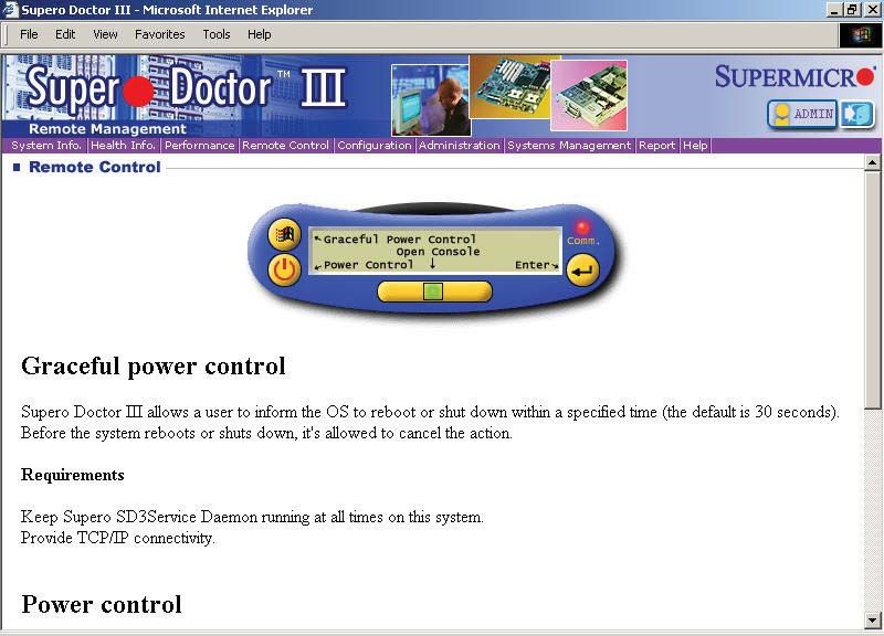
The information in this User’s Manual has been carefully reviewed and is believed to be accurate.
The vendor assumes no responsibility for any inaccuracies that may be contained in this document,
makes no commitment to update or to keep current the information in this manual, or to notify any
person or organization of the updates. Please Note: For the most up-to-date version of this
manual, please see our web site at www.supermicro.com.

Super Micro Computer, Inc. ("Supermicro") reserves the right to make changes to the product
described in this manual at any time and without notice. This product, including software and
documentation, is the property of Supermicro and/or its licensors, and is supplied only under a
license. Any use or reproduction of this product is not allowed, except as expressly permitted by
the terms of said license.

IN NO EVENT WILL SUPERMICRO BE LIABLE FOR DIRECT, INDIRECT, SPECIAL, INCIDENTAL,
SPECULATIVE OR CONSEQUENTIAL DAMAGES ARISING FROM THE USE OR INABILITY TO
USE THIS PRODUCT OR DOCUMENTATION, EVEN IF ADVISED OF THE POSSIBILITY OF
SUCH DAMAGES. IN PARTICULAR, SUPERMICRO SHALL NOT HAVE LIABILITY FOR ANY
HARDWARE, SOFTWARE, OR DATA STORED OR USED WITH THE PRODUCT, INCLUDING THE
COSTS OF REPAIRING, REPLACING, INTEGRATING, INSTALLING OR RECOVERING SUCH
HARDWARE, SOFTWARE, OR DATA.

Any disputes arising between manufacturer and customer shall be governed by the laws of Santa
Clara County in the State of California, USA. The State of California, County of Santa Clara shall
be the exclusive venue for the resolution of any such disputes. Super Micro's total liability for all
claims will not exceed the price paid for the hardware product.

FCC Statement: This equipment has been tested and found to comply with the limits for a Class
A digital device pursuant to Part 15 of the FCC Rules. These limits are designed to provide
reasonable protection against harmful interference when the equipment is operated in a commercial
environment. This equipment generates, uses, and can radiate radio frequency energy and, if not
installed and used in accordance with the manufacturer’s instruction manual, may cause harmful
interference with radio communications. Operation of this equipment in a residential area is likely
to cause harmful interference, in which case you will be required to correct the interference at your
own expense.

California Best Management Practices Regulations for Perchlorate Materials: This Perchlorate
warning applies only to products containing CR (Manganese Dioxide) Lithium coin cells. “Perchlorate
Material-special handling may apply. See www.dtsc.ca.gov/hazardouswaste/perchlorate”

WARNING: Handling of lead solder materials used in this
product may expose you to lead, a chemical known to
the State of California to cause birth defects and other
reproductive harm.
Manual Revision 1.0
Release Date: April 22, 2010

Unless you request and receive written permission from Super Micro Computer, Inc., you may not
copy any part of this document.

Information in this document is subject to change without notice. Other products and companies
referred to herein are trademarks or registered trademarks of their respective companies or mark
holders.

Copyright © 2010 by Super Micro Computer, Inc.
All rights reserved.
Printed in the United States of America
Preface

                                   Preface

About This Manual
  This manual is written for professional system integrators and PC technicians. It
  provides information for the installation and use of the SuperServer 2022G-URF.
  Installation and maintainance should be performed by experienced technicians
  only.
  The SuperServer 2022G-URF is a high-end server based on the SC825TQ-R720UB
  2U rackmount chassis and the H8DGU-F dual processor serverboard.

Manual Organization

  Chapter 1: Introduction
  The first chapter provides a checklist of the main components included with the
  server system and describes the main features of the H8DGU-F serverboard and
  the SC825TQ-R720UB chassis.

  Chapter 2: Server Installation
  This chapter describes the steps necessary to install the SuperServer 2022G-URF
  into a rack and check out the server configuration prior to powering up the system.
  If your server was ordered without processor and memory components, this chapter
  will refer you to the appropriate sections of the manual for their installation.

  Chapter 3: System Interface
  Refer here for details on the system interface, which includes the functions and
  information provided by the control panel on the chassis as well as other LEDs
  located throughout the system.

  Chapter 4: System Safety
  You should thoroughly familiarize yourself with this chapter for a general overview
  of safety precautions that should be followed when installing and servicing the
  SuperServer 2022G-URF.

  Chapter 5: Advanced Serverboard Setup
  Chapter 5 provides detailed information on the H8DGU-F serverboard, including the
  locations and functions of connections, headers and jumpers. Refer to this chapter
  when adding or removing processors or main memory and when reconfiguring the
  serverboard.

                                        iii
SUPERSERVER 2022G-URF User's Manual
Chapter 6: Advanced Chassis Setup
Refer to Chapter 6 for detailed information on the SC825TQ-R720UB server chassis.
You should follow the procedures given in this chapter when installing, removing
or reconfiguring SAS/SATA or peripheral drives and when replacing system power
supply units and cooling fans.
Chapter 7: BIOS
The BIOS chapter includes an introduction to BIOS and provides detailed information
on running the CMOS Setup Utility.
Appendix A: BIOS Error Beep Codes
Appendix B: Installing Windows
Appendix C: System Specifications
ivPreface Notes v
SUPERSERVER 2022G-URF User's Manual

                                           Table of Contents

Chapter 1 Introduction
1-1      Overview ......................................................................................................... 1-1
1-2      Serverboard Features ..................................................................................... 1-2
         Processors ...................................................................................................... 1-2
         Memory ........................................................................................................... 1-2
         UIO .................................................................................................................. 1-2
         Serial ATA ....................................................................................................... 1-2
         Onboard Controllers/Ports .............................................................................. 1-2
         Graphics Controller ......................................................................................... 1-3
         Other Features ................................................................................................ 1-3
1-3      Server Chassis Features ................................................................................ 1-3
         System Power ................................................................................................. 1-3
         Hard Drive Subsystem .................................................................................... 1-3
         Front Control Panel ......................................................................................... 1-3
         I/O Backplane.................................................................................................. 1-4
         Cooling System ............................................................................................... 1-4
1-4      Contacting Supermicro .................................................................................... 1-6
Chapter 2 Server Installation
2-1      Overview ......................................................................................................... 2-1
2-2      Unpacking the System .................................................................................... 2-1
2-3      Preparing for Setup ......................................................................................... 2-1
         Choosing a Setup Location ............................................................................. 2-1
Warnings and Precautions! ........................................................................................ 2-2
         Rack Precautions ............................................................................................ 2-2
         Server Precautions.......................................................................................... 2-2
         Rack Mounting Considerations ....................................................................... 2-3
             Ambient Operating Temperature ................................................................ 2-3
             Reduced Airflow ......................................................................................... 2-3
             Mechanical Loading ................................................................................... 2-3
             Circuit Overloading ..................................................................................... 2-3
             Reliable Ground ......................................................................................... 2-3
2-4      Installing the System into a Rack ................................................................... 2-4
         Separating the Sections of the Rack Rails ..................................................... 2-4
         Installing the Inner Rail Extension .................................................................. 2-4
         Outer Rack Rails ............................................................................................. 2-6
2-5      Checking the Serverboard Setup .................................................................... 2-8

                                                               vi
Table of Contents
2-6 Checking the Drive Bay Setup ...................................................................... 2-10
Chapter 3 System Interface
3-1 Overview ......................................................................................................... 3-1
3-2 Control Panel Buttons ..................................................................................... 3-1
Reset ............................................................................................................... 3-1
Power .............................................................................................................. 3-1
3-3 Control Panel LEDs ........................................................................................ 3-2
Power Fail ....................................................................................................... 3-2
Overheat/Fan Fail: .......................................................................................... 3-2
NIC1 ................................................................................................................ 3-2
NIC2 ................................................................................................................ 3-2
HDD................................................................................................................. 3-3
Power .............................................................................................................. 3-3
3-4 Drive Carrier LEDs .......................................................................................... 3-3
Chapter 4 System Safety
4-1 Electrical Safety Precautions .......................................................................... 4-1
4-2 General Safety Precautions ............................................................................ 4-2
4-3 ESD Precautions ............................................................................................. 4-3
4-4 Operating Precautions .................................................................................... 4-4
Chapter 5 Advanced Serverboard Setup
5-1 Handling the Serverboard ............................................................................... 5-1
Precautions ..................................................................................................... 5-1
Unpacking ....................................................................................................... 5-1
5-2 Processor and Heatsink Installation................................................................ 5-2
When handling the processor, avoid placing direct pressure on the label area of the
fan. Also, do not place the serverboard on a conductive surface, which can damage
the BIOS battery and prevent the system from booting up. ...................................... 5-2
Installing a Passive CPU Heatsink ................................................................. 5-4
5-3 Connecting Cables .......................................................................................... 5-5
Connecting Data Cables ................................................................................. 5-5
Connecting Power Cables .............................................................................. 5-5
Connecting the Control Panel ......................................................................... 5-5
5-4 I/O Ports .......................................................................................................... 5-6
5-5 Installing Memory ............................................................................................ 5-7
Memory Support .............................................................................................. 5-7
DIMM Module Population Configuration .................................................... 5-8
5-6 Adding PCI Expansion Cards ......................................................................... 5-9
5-7 Serverboard Details ...................................................................................... 5-10
H8DGU(-F) Quick Reference .........................................................................5-11
viiSUPERSERVER 2022G-URF User's Manual
5-8 Connector Definitions ................................................................................... 5-12
5-9 Jumper Settings ............................................................................................ 5-18
Explanation of Jumpers ................................................................................ 5-18
5-10 Onboard Indicators........................................................................................ 5-20
5-11 SATA Drive Connections ............................................................................... 5-21
5-12 Enabling SATA RAID ..................................................................................... 5-22
Serial ATA (SATA).......................................................................................... 5-22
Installing the OS/SATA Driver ....................................................................... 5-22
Building a Driver Diskette ......................................................................... 5-22
Enabling SATA RAID in the BIOS ................................................................. 5-23
Using the Adaptec RAID Utility ..................................................................... 5-24
Installing the RAID Driver During OS Installation ......................................... 5-24
5-13 Installing Drivers............................................................................................ 5-25
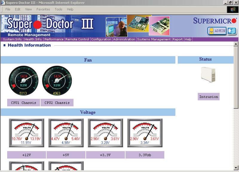
Supero Doctor III ........................................................................................... 5-26
Chapter 6 Advanced Chassis Setup
6-1 Static-Sensitive Devices .................................................................................. 6-1
Precautions ..................................................................................................... 6-1
Unpacking ....................................................................................................... 6-1
6-2 Control Panel .................................................................................................. 6-2
6-3 System Fans ................................................................................................... 6-3
System Fan Failure ......................................................................................... 6-3
Replacing System Fans .................................................................................. 6-4
6-4 Drive Bay Installation/Removal ....................................................................... 6-4
Accessing the Drive Bays ............................................................................... 6-4
SAS/SATA Drive Installation............................................................................ 6-5
Hard Drive Backplane ..................................................................................... 6-6
DVD-ROM Installation ..................................................................................... 6-7
6-5 Power Supply .................................................................................................. 6-8
Power Supply Failure ...................................................................................... 6-8
Removing/Replacing the Power Supply.......................................................... 6-8
Chapter 7 BIOS
7-1 Introduction...................................................................................................... 7-1
Starting the Setup Utility ................................................................................. 7-1
7-2 Main Menu ...................................................................................................... 7-1
System Time/System Date ............................................................................. 7-2
7-3 Advanced Settings Menu ................................................................................ 7-2
7-4 Security Menu ............................................................................................... 7-13
7-5 Boot Menu ..................................................................................................... 7-14
viiiTable of Contents
7-6 Exit Menu ...................................................................................................... 7-15
Appendix A BIOS Error Beep Codes
Appendix B Installing Windows
B-1 Installing the Windows OS for a RAID System .............................................. B-1
B-2 Installing the Windows OS for a Non-RAID System ....................................... B-2
Appendix C System Specifications
ixSUPERSERVER 2022G-URF User's Manual
Notes
xChapter 1: Introduction
Chapter 1
Introduction
1-1 Overview
The SuperServer 2022G-URF is a high-end server comprised of two main
subsystems: the SC825TQ-R720UB 2U server chassis and the H8DGU-F dual
processor serverboard. Please refer to our web site for information on operating
systems that have been certified for use with the system (www.supermicro.com).
In addition to the serverboard and chassis, various hardware components have
been included with the 2022G-URF, as listed below:
• One (1) Slim SATA DVD kit (MCP-220-81502-0N)
• One (1) Slim DVD-ROM drive (DVM-TEAC-DVD-SBT or DVM-PNSC-DVD-
SBT)
• One (1) SATA to USB adapter for slim DVD-ROM drive (CDM-USATA-G)
• One (1) Internal USB cable for DVD-ROM drive (CBL-0341L)
• Two (2) 2U Passive CPU HS for AMD Socket G34 (SNK-P0043P)
• One (1) Air shroud (MCP-310-28001-0N)
• One (1) Riser card (RSC-R2UU-UA3E8+)
• SAS/SATA Accessories
One (1) SAS/SATA backplane (BPN-SAS-825TQ)
Two (2) iPass to SATA cables (CBL-0188L)
Eight (8) Drive carriers (MCP-220-00001-01)
• One (1) Rackmount kit (MCP-290-00053-0N)
• One CD containing drivers and utilities
1-1SUPERSERVER 2022G-URF User's Manual
1-2 Serverboard Features
At the heart of the SuperServer 2022G-URF lies the H8DGU-F, a dual processor
serverboard based on the AMD SR5670/SP5100 chipset. Below are the main
features of the H8DGU-F. (See Figure 1-1 for a block diagram of the chipset).
Processors
The H8DGU-F supports single or dual AMD Opteron 6100 Series processors in
Socket G34 type sockets. Please refer to our web site for a complete listing of
supported processors (www.supermicro.com).
Memory
The H8DGU-F has sixteen single/dual/tri/quad channel 240-pin DIMM sockets that
can support up to 256GB of DDR3-1333/1066/800MHz registered ECC SDRAM or
64 GB of DDR3-1333/1066/800 MHz unbuffered ECC/non-ECC SDRAM. Please
refer to Chapter 5 for installing memory.
UIO
The H8DGU-F is a specially-designed serverboard that features Supermicro's UIO
(Universal I/O) technology. UIO serverboards have a PCI Express x8 slot that can
support any one of several types of UIO card types to add SAS ports, additional
LAN ports, etc. to the serverboard. This allows the user to tailor the serverboard
to their own needs.
Note: the server does not come with a UIO card installed.
Serial ATA
An on-chip (SP5100) SATA controller is integrated into the H8DGU-F to provide
a six-port, 3 Gb/sec SATA subsystem, which is RAID 0, 1, and 10 supported. The
SATA drives are hot-swappable units.
Note: You must have RAID set up to enable the hot-swap capability of the SATA
drives. Documentation on RAID setup guidelines can be found on our web site.
Onboard Controllers/Ports
The color-coded I/O ports include two COM ports (one header and one port), a VGA
(monitor) port, Seven USB 2.0 ports (2x rear, 4x header, 1x type A), PS/2 mouse
and keyboard ports, two gigabit Ethernet ports and one dedicated IPMI LAN port.
1-2Chapter 1: Introduction
Graphics Controller
The H8DGU-F features an integrated Matrox G200eW graphics chip, which includes
16 MB of DDR2 memory.
Other Features
Other onboard features that promote system health include onboard voltage
monitors, auto-switching voltage regulators, chassis and CPU overheat sensors,
virus protection and BIOS rescue.
1-3 Server Chassis Features
The 2022G-URF is built upon the SC825TQ-R720UB chassis. Details on the chassis
and on servicing procedures can be found in Chapter 6. The following is a general
outline of the main features of the chassis.
System Power
The SC825TQ-R720UB features a redundant 720W power supply consisting of
two power modules. The system does not need to be shut down when replacing or
removing a single power supply module.
Hard Drive Subsystem
The SC825TQ-R720UB chassis was designed to support eight hot-swap SATA or
SAS hard drives. (Requires UIO controller card - not included with system.)
Note: A SAS or SATA UIO card must be installed to support SAS or SATA
drives.
Front Control Panel
The control panel on the SuperServer 2022G-URF provides you with system
monitoring and control. LEDs indicate system power, HDD activity, network activity,
system overheat and power supply failure. A main power button and a system reset
button are also included. In addition, two USB ports have been incorporated into
the control panel to provide front side USB access.
1-3SUPERSERVER 2022G-URF User's Manual
I/O Backplane
The SC825TQ-R720UB is an ATX form factor chassis designed to be used in a 2U
rackmount configuration. The I/O backplane provides four standard-size add-on card
slots, one COM port, a VGA port, two USB 2.0 ports, PS/2 mouse and keyboard
ports, a dedicated IPMI LAN port and two gigabit Ethernet ports.
Cooling System
The SC825TQ-R720UB chassis has an innovative cooling design that includes three
8-cm hot-plug system cooling fans located in the middle section of the chassis. An
air shroud channels the airflow from the system fans to efficiently cool the processor
area of the system. The power supply module also includes a cooling fan.
1-4Chapter 1: Introduction
Figure 1-1. AMD SR5670/SP5100 Chipset:
System Block Diagram
Note: This is a general block diagram. Please see Chapter 5 for details.
DIMM A1 HT3 Link
DIMM A0 8x8-3.2GT/s DIMM A1
DIMM B1 DIMM A0
DIMM B0 AMD AMD DIMM B1
HT3 Link
DIMM C1 Socket G34 Socket G34 DIMM B0
DIMM C0 8x8-3.2GT/s DIMM C1
CPU2 CPU1 DIMM C0
DIMM D1
DIMM D0 HT3 Link DIMM D1
(8+8)x(8+8)-6.4GT/s DIMM D0
HT3 Link
16x16-5.2GT/s
RJ45 PCI-E GEN2 x16
INTEL PCI-E GEN2 X4
Slot1
KAWELA SR5670
RJ45
Slot3
PCI-E GEN2 x8 (in x4)
RMII
A-Link
MUX Clock Gen
VGA
DDR2 SDRAM PCI
64Mb X16bit
BMC
PSU I2C VGA SMBus SP5100 SATA x6
WPCM450-R
IPMB LPC
COM1 TPM (/OPT)
COM2 SPI Flash
SIO
HWM KB/MS
W83527
W83795G
FE PHY RJ45 7xUSB
RTL8201N
1-5SUPERSERVER 2022G-URF User's Manual
1-4 Contacting Supermicro
Headquarters
Address: Super Micro Computer, Inc.
980 Rock Ave.
San Jose, CA 95131 U.S.A.
Tel: +1 (408) 503-8000
Fax: +1 (408) 503-8008
Email: marketing@supermicro.com (General Information)
support@supermicro.com (Technical Support)
Web Site: www.supermicro.com
Europe
Address: Super Micro Computer B.V.
Het Sterrenbeeld 28, 5215 ML
's-Hertogenbosch, The Netherlands
Tel: +31 (0) 73-6400390
Fax: +31 (0) 73-6416525
Email: sales@supermicro.nl (General Information)
support@supermicro.nl (Technical Support)
rma@supermicro.nl (Customer Support)
Asia-Pacific
Address: Super Micro Computer, Inc.
4F, No. 232-1, Liancheng Rd.
Chung-Ho 235, Taipei County
Taiwan, R.O.C.
Tel: +886-(2) 8226-3990
Fax: +886-(2) 8226-3991
Web Site: www.supermicro.com.tw
Technical Support:
Email: support@supermicro.com.tw
Tel: 886-2-8228-1366, ext.132 or 139
1-6Chapter 2: Server Installation
Chapter 2
Server Installation
2-1 Overview
This chapter provides a quick setup checklist to get your SuperServer 2022G-URF
up and running. Following these steps in the order given should enable you to have
the system operational within a minimum amount of time. This quick setup assumes
that your system has come to you with the processors and memory preinstalled. If
your system is not already fully integrated with a serverboard, processors, system
memory etc., please turn to the chapter or section noted in each step for details on
installing specific components.
2-2 Unpacking the System
You should inspect the box the SuperServer 2022G-URF was shipped in and note
if it was damaged in any way. If the server itself shows damage you should file a
damage claim with the carrier who delivered it.
Decide on a suitable location for the rack unit that will hold the SuperServer 2022G-
URF. It should be situated in a clean, dust-free area that is well ventilated. Avoid
areas where heat, electrical noise and electromagnetic fields are generated. You
will also need it placed near a grounded power outlet. Read the Rack and Server
Precautions in the next section.
2-3 Preparing for Setup
The box the SuperServer 2022G-URF was shipped in should include two sets of
rail assemblies, two rail mounting brackets and the mounting screws you will need
to install the system into the rack. Follow the steps in the order given to complete
the installation process in a minimum amount of time. Please read this section in
its entirety before you begin the installation procedure outlined in the sections that
follow.
Choosing a Setup Location
• Leave enough clearance in front of the rack to enable you to open the front door
completely (~25 inches) and approximately 30 inches of clearance in the back
of the rack to allow for sufficient airflow and ease in servicing.
2-1SUPERSERVER 2022G-URF User's Manual
• This product is for installation only in a Restricted Access Location (dedicated
equipment rooms, service closets and the like).
• This product is not suitable for use with visual display work place devices
acccording to §2 of the the German Ordinance for Work with Visual Display
Units.
!
Warnings and Precautions! !
Rack Precautions
• Ensure that the leveling jacks on the bottom of the rack are fully extended to
the floor with the full weight of the rack resting on them.
• In single rack installation, stabilizers should be attached to the rack. In multiple
rack installations, the racks should be coupled together.
• Always make sure the rack is stable before extending a component from the
rack.
• You should extend only one component at a time - extending two or more si-
multaneously may cause the rack to become unstable.
Server Precautions
• Review the electrical and general safety precautions in Chapter 4.
• Determine the placement of each component in the rack before you install the
rails.
• Install the heaviest server components on the bottom of the rack first, and then
work up.
• Use a regulating uninterruptible power supply (UPS) to protect the server from
power surges, voltage spikes and to keep your system operating in case of a
power failure.
• Allow any hot plug drives and power supply modules to cool before touching
them.
• Always keep the rack's front door and all panels and components on the servers
closed when not servicing to maintain proper cooling.
2-2Chapter 2: Server Installation
Rack Mounting Considerations
Ambient Operating Temperature
If installed in a closed or multi-unit rack assembly, the ambient operating
temperature of the rack environment may be greater than the ambient temperature
of the room. Therefore, consideration should be given to installing the equipment
in an environment compatible with the manufacturer’s maximum rated ambient
temperature (Tmra).
Reduced Airflow
Equipment should be mounted into a rack so that the amount of airflow required
for safe operation is not compromised.
Mechanical Loading
Equipment should be mounted into a rack so that a hazardous condition does not
arise due to uneven mechanical loading.
Circuit Overloading
Consideration should be given to the connection of the equipment to the power
supply circuitry and the effect that any possible overloading of circuits might have
on overcurrent protection and power supply wiring. Appropriate consideration of
equipment nameplate ratings should be used when addressing this concern.
Reliable Ground
A reliable ground must be maintained at all times. To ensure this, the rack
itself should be grounded. Particular attention should be given to power supply
connections other than the direct connections to the branch circuit (i.e. the use of
power strips, etc.).
2-3SUPERSERVER 2022G-URF User's Manual
2-4 Installing the System into a Rack
This section provides information on installing the SC825 chassis into a rack unit
with the quick-release rails provided. There are a variety of rack units on the market,
which may mean the assembly procedure will differ slightly. You should also refer to
the installation instructions that came with the rack unit you are using.
Note: This rail will fit a rack between 26" and 33.5" deep.
Separating the Sections of the Rack Rails
The chassis package includes two rail assemblies in the rack mounting kit. Each
assembly consists of two sections: an inner fixed chassis rail that secures directly
to the server chassis and an outer fixed rack rail that secures directly to the rack
itself.
Installing the Inner Rail Extension
The SC825 chassis includes a set of inner rails in two sections: inner rails and inner
rail extensions. The inner rails are pre-attached to the chassis, and do not interfere
with normal use of the chassis if you decide not to use a server rack. The inner rail
extension is attached to the inner rail to mount the chassis in the rack.
Installing the Inner Rails
1. Place the inner rail extensions on the side of the chassis aligning the hooks
of the chassis with the rail extension holes. Make sure the extension faces
"outward" just like the pre-attached inner rail.
2. Slide the extension toward the front of the chassis.
3. Secure the chassis with 2 screws as illustrated. Repeat steps for the other
inner rail extension.
2-4Chapter 2: Server Installation
Figure 2-1: Separating the Rack Rails
Separating the Inner and Outer
Rails
1 Rail Assembly 1. Locate the rail assembly in the
chassis packaging.
2. Extend the rail assembly by
Extending the Rails
pulling it outward.
12 3. Press the quick-release tab.
4. Separate the inner rail
13 Quick-Release Tab
extension from the outer rail
assembly.
Separating
14 the Inner Rail
Extension
2-5SUPERSERVER 2022G-URF User's Manual
Figure 2-2. Assembling the Outer Rails
13
12 1
Outer Rack Rails
Outer rails attach to the rack and hold the chassis in place. The outer rails for the
SC825 chassis extend between 30 inches and 33 inches.
Installing the Outer Rails to the Rack
1. Secure the back end of the outer rail to the rack, using the screws provided.
2. Press the button where the two outer rails are joined to retract the smaller
outer rail.
3. Hang the hooks of the rails onto the rack holes and if desired, use screws to
secure the front of the outer rail onto the rack.
4. Repeat steps 1-3 for the remaining outer rail.
2-6Chapter 2: Server Installation
Figure 2-3. Installing the Rack Rails
Installing the Chassis into a Rack
1. Extend the outer rails as illustrated above.
2. Align the inner rails of the chassis with the outer rails on the rack.
3. Slide the inner rails into the outer rails, keeping the pressure even on both
sides. When the chassis has been pushed completely into the rack, it should
click into the locked position.
4. Optional screws may be used to secure the to hold the front of the chassis to
the rack.
2-7SUPERSERVER 2022G-URF User's Manual
2-5 Checking the Serverboard Setup
After you install the 2022G-URF in the rack, you will need to open the unit to
make sure the serverboard is properly installed and all the connections have been
made.
Accessing the inside of the System
1. First, grasp the two handles on either side and pull the unit straight out until it
locks (you will hear a "click").
2. Next, depress the two buttons on the top of the chassis to release the top
cover.
3. You can then lift the top cover from the chassis to gain full access to the
inside of the server.
Checking the Components and Setup
1. You may have one or two processors already installed into the serverboard.
Each processor needs its own heat sink. See Chapter 5 for instructions on
processor and heat sink installation.
2. Your 2022G-URF server system may have come with system memory already
installed. Make sure all DIMMs are fully seated in their slots. For details on
adding system memory, refer to Chapter 5.
3. If desired, you can install add-on cards to the system. See Chapter 5 for
details on installing PCI add-on cards.
4. Make sure all power and data cables are properly connected and not blocking
the chassis airflow. Also make sure that no cables are positioned in front of
the fans. See Chapter 5 for details on cable connections.
2-8Chapter 2: Server Installation
Figure 2-3. Accessing the Inside of the System
2-9SUPERSERVER 2022G-URF User's Manual
2-6 Checking the Drive Bay Setup
Next, you should check to make sure the peripheral drives and the SAS/SATA drives
have been properly installed and all connections have been made.
Checking the Drives
1. All drives are accessable from the front of the server. For servicing the DVD-
ROM, you will need to remove the top chassis cover. The hard drives can be
installed and removed from the front of the chassis without removing the top
chassis cover.
2. A slim DVD-ROM may be preinstalled in your server. Refer to Chapter 6 if
you need to install a DVD-ROM drive to the system.
3. Depending upon your system's configuration, your system may have one or
more drives already installed. If you need to install hard drives, please refer to
Chapter 6.
Checking the Airflow
1. Airflow is provided by three hot-swappable 8-cm chassis cooling fans. The
system component layout was carefully designed to direct sufficient cooling
airflow to the components that generate the most heat.
2. Note that all power and data cables have been routed in such a way that they
do not block the airflow generated by the fans.
Providing Power
1. Plug the power cord(s) from the power supply unit(s) into a high-quality
power strip that offers protection from electrical noise and power surges. It is
recommended that you use an uninterruptible power supply (UPS).
2. Depress the power on button on the front of the chassis.
2-10Chapter 3: System Interface
Chapter 3
System Interface
3-1 Overview
There are several LEDs on the control panel as well as others on the drive carriers
to keep you constantly informed of the overall status of the system as well as
the activity and health of specific components. There are also two buttons on the
chassis control panel.
3-2 Control Panel Buttons
There are two buttons located on the front of the chassis: a reset button and a
power on/off button.
Reset
Use the reset button to reboot the system.
Power
This is the main power button, which is used to apply or turn off the main system
power. Turning off system power with this button removes the main power but keeps
standby power supplied to the system.
3-1SUPERSERVER 2022G-URF User's Manual
3-3 Control Panel LEDs
The control panel located on the front of the chassis has several LEDs. These
LEDs provide you with critical information related to different parts of the system.
This section explains what each LED indicates when illuminated and any corrective
action you may need to take.
Power Fail
Indicates a power supply module has failed. The second power supply module will
take the load and keep the system running but the failed module will need to be
replaced. Refer to Chapter 6 for details on replacing the power supply. This LED
should be off when the system is operating normally.
Overheat/Fan Fail:
When this LED flashes, it indicates a fan failure. When on continuously it indicates
an overheat condition, which may be caused by cables obstructing the airflow in
the system or the ambient room temperature being too warm. Check the routing of
the cables and make sure all fans are present and operating normally. You should
also check to make sure that the chassis covers are installed. Finally, verify that
the heatsinks are installed properly (see Chapter 5). This LED will remain flashing
or on as long as the indicated condition exists.
1
NIC1
Indicates network activity on the LAN1 port when flashing.
2
NIC2
Indicates network activity on the LAN2 port when flashing.
3-2Chapter 3: System Interface
HDD
On the SuperServer 2022G-URF, this LED indicates hard drive and/or DVD-ROM
drive activity when flashing.
Power
Indicates power is being supplied to the system's power supply units. This LED
should normally be illuminated when the system is operating.
3-4 Drive Carrier LEDs
Each drive carrier has two LEDs:
SATA Drives
• Green: When illuminated, the green LED on the SATA drive carrier indicates
drive activity. A connection to the SATA backplane enables this LED to blink
on and off when that particular drive is being accessed. Please refer to Chapter
6 for instructions on replacing failed SATA drives.
• Red: When this LED flashes it indicates the drive is rebuilding. When solid on
it indicates a SATA drive failure. If a drive fails, you should be notified by your
system management software. Please refer to Chapter 6 for instructions on
replacing failed drives.
SAS Drives
• Green: When illuminated, the green LED on the drive carrier indicates the SAS
drive is powered on. If this LED is not lit, it means no power is being provided for
the drive. Please refer to Chapter 6 for instructions on replacing failed drives.
• Red: When this LED flashes it indicates the drive is rebuilding. When solid on
it indicates a SAS drive failure. If a drive fails, you should be notified by your
system management software. Please refer to Chapter 6 for instructions on
replacing failed drives.
3-3SUPERSERVER 2022G-URF User's Manual
Notes
3-4Chapter 4: System Safety
Chapter 4
System Safety
4-1 Electrical Safety Precautions
!
Basic electrical safety precautions should be followed to protect yourself from harm
and the SuperServer 2022G-URF from damage:
• Be aware of the locations of the power on/off switch on the chassis as well
as the room's emergency power-off switch, disconnection switch or electrical
outlet. If an electrical accident occurs, you can then quickly remove power from
the system.
• Do not work alone when working with high voltage components.
• Power should always be disconnected from the system when removing or in-
stalling main system components, such as the serverboard, memory modules
and floppy drive. When disconnecting power, you should first power down the
operating system first and then unplug the power cords. The unit has more than
one power supply cord. Disconnect two power supply cords before servicing to
avoid electrical shock.
• When working around exposed electrical circuits, another person who is familiar
with the power-off controls should be nearby to switch off the power if neces-
sary.
• Use only one hand when working with powered-on electrical equipment. This
is to avoid making a complete circuit, which will cause electrical shock. Use
extreme caution when using metal tools, which can easily damage any electrical
components or circuit boards they come into contact with.
• Do not use mats designed to decrease static electrical discharge as protection
from electrical shock. Instead, use rubber mats that have been specifically
designed as electrical insulators.
• The power supply power cords must include a grounding plug and must be
plugged into grounded electrical outlets.
4-1SUPERSERVER 2022G-URF User's Manual
• This product may be connected to an IT power system. In all cases, make sure
that the unit is also reliably connected to Earth (ground).
• Serverboard Battery: CAUTION - There is a danger of explosion if the onboard
battery is installed upside down, which will reverse its polarites (see Figure
4-1). This battery must be replaced only with the same or an equivalent type
recommended by the manufacturer. Dispose of used batteries according to the
manufacturer's instructions.
• DVD-ROM Laser: CAUTION - this server may have come equipped with a
DVD-ROM drive. To prevent direct exposure to the laser beam and hazardous
radiation exposure, do not open the enclosure or use the unit in any uncon-
ventional way.
• Mainboard replaceable soldered-in fuses: Self-resetting PTC (Positive Tempera-
ture Coefficient) fuses on the mainboard must be replaced by trained service
technicians only. The new fuse must be the same or equivalent as the one
replaced. Contact technical support for details and support.
4-2 General Safety Precautions
!
Follow these rules to ensure general safety:
• Keep the area around the 2022G-URF clean and free of clutter.
• The 2022G-URF weighs approximately 57 lbs. (25.85 kg.) when fully loaded.
When lifting the system, two people at either end should lift slowly with their
feet spread out to distribute the weight. Always keep your back straight and lift
with your legs.
• Place the chassis top cover and any system components that have been re-
moved away from the system or on a table so that they won't accidentally be
stepped on.
• While working on the system, do not wear loose clothing such as neckties and
unbuttoned shirt sleeves, which can come into contact with electrical circuits or
be pulled into a cooling fan.
4-2Chapter 4: System Safety
• Remove any jewelry or metal objects from your body, which are excellent metal
conductors that can create short circuits and harm you if they come into contact
with printed circuit boards or areas where power is present.
• After accessing the inside of the system, close the system back up and secure
it to the rack unit with the retention screws after ensuring that all connections
have been made.
4-3 ESD Precautions
!
Electrostatic discharge (ESD) is generated by two objects with different electrical
charges coming into contact with each other. An electrical discharge is created to
neutralize this difference, which can damage electronic components and printed
circuit boards. The following measures are generally sufficient to neutralize this
difference before contact is made to protect your equipment from ESD:
• Use a grounded wrist strap designed to prevent static discharge.
• Keep all components and printed circuit boards (PCBs) in their antistatic bags
until ready for use.
• Touch a grounded metal object before removing the board from the antistatic
bag.
• Do not let components or PCBs come into contact with your clothing, which may
retain a charge even if you are wearing a wrist strap.
• Handle a board by its edges only; do not touch its components, peripheral chips,
memory modules or contacts.
• When handling chips or modules, avoid touching their pins.
• Put the serverboard and peripherals back into their antistatic bags when not
in use.
• For grounding purposes, make sure your computer chassis provides excellent
conductivity between the power supply, the case, the mounting fasteners and
the serverboard.
4-3SUPERSERVER 2022G-URF User's Manual
4-4 Operating Precautions
!
Care must be taken to assure that the chassis cover is in place when the 2022G-
URF is operating to assure proper cooling. Out of warranty damage to the system
can occur if this practice is not strictly followed.
Figure 4-1. Installing the Onboard Battery
LITHIUM BATTERY
BATTERY HOLDER
Please handle used batteries carefully. Do not damage the battery in any
way; a damaged battery may release hazardous materials into the envi-
!
ronment. Do not discard a used battery in the garbage or a public landfill.
Please comply with the regulations set up by your local hazardous waste
management agency to dispose of your used battery properly.
4-4Chapter 5: Advanced Serverboard Setup
Chapter 5
Advanced Serverboard Setup
This chapter covers the steps required to install processors and heatsinks to the
H8DGU-F serverboard, connect the data and power cables and install add-on
cards. All serverboard jumpers and connections are described and a layout and
quick reference chart are included in this chapter. Remember to close the chassis
completely when you have finished working on the serverboard to protect and cool
the system sufficiently.
5-1 Handling the Serverboard
Static electrical discharge can damage electronic components. To prevent damage
to printed circuit boards, it is important to handle them very carefully (see Chapter 4).
Also note that the size and weight of the serverboard can cause it to bend if handled
improperly, which may result in damage. To prevent the serverboard from bending,
keep one hand under the center of the board to support it when handling.
The following measures are generally sufficient to protect your equipment from
static discharge.
Precautions
• Use a grounded wrist strap designed to prevent static discharge.
• Touch a grounded metal object before removing any board from its antistatic
bag.
• Handle a board by its edges only; do not touch its components, peripheral chips,
memory modules or gold contacts.
• When handling chips or modules, avoid touching their pins.
• Put the serverboard, add-on cards and peripherals back into their antistatic
bags when not in use.
Unpacking
The serverboard is shipped in antistatic packaging to avoid static damage. When
unpacking the board, make sure the person handling it is static protected.
5-1SUPERSERVER 2022G-URF User's Manual
5-2 Processor and Heatsink Installation
When handling the processor, avoid placing direct pressure on the label
area of the fan. Also, do not place the serverboard on a conductive
! surface, which can damage the BIOS battery and prevent the system
from booting up.
IMPORTANT! Always connect the power cord last and remove it first before
adding, removing or changing any hardware components. Make sure that you
install the processor into the CPU socket before you install the heatsink and fan.
The H8DGU-F can support either one or two processors. If installing one processor
only, install it into the CPU1 socket.
Note: When purchasing a CPU or when receiving a serverboard with a CPU pre-
installed, make sure that the CPU plastic cap is in place and none of the CPU pins
are bent; otherwise, contact the retailer immediately.
Installing the Processors
1. Begin by removing the cover plate that
protects the CPU. Lift the lever on the
CPU socket until it points straight up.
2. With the lever raised, lift open the silver
CPU retention plate.
5-2Chapter 5: Advanced Serverboard Setup
3. Use your thumb and your index finger
to hold the CPU. Locate and align pin
1 of the CPU socket with pin 1 of the
CPU. Both are marked with a triangle.
4. Align pin 1 of the CPU with pin 1 of the
socket. Once aligned, carefully place
the CPU into the socket. Do not drop
the CPU on the socket, move the CPU
horizontally or vertically or rub the CPU Triangle
against the socket or against any pins
of the socket, which may damage the
CPU and/or the socket.
5. With the CPU inserted into the socket,
inspect the four corners of the CPU to
make sure that it is properly installed
and flush with the socket. Then, gently
lower the silver CPU retention plate into
place.
6. Carefully press the CPU socket lever
down until it locks into its retention
tab. For a dual-CPU system, repeat
these steps to install another CPU into
the CPU#2 socket (and into CPU#2,
#3 and #4 sockets for a quad-CPU
configuration).
Note: in single and dual-CPU configurations, memory must be installed in the DIMM
slots associated with the installed CPU(s). Memory is limited to a maximum of 128
for single CPU and 256 GB for dual CPU configurations.
5-3SUPERSERVER 2022G-URF User's Manual
Installing a Passive CPU Heatsink
1. Do not apply any thermal grease to the heatsink or the CPU die -- the
required amount has already been applied.
2. Place the heatsink directly on top of the CPU so that the heat sink screws are
aligned with the mounting holes on the back plate.
3. Make sure the screwdriver torgue setting is no more than 5.0 Kgf-cm (4.3 lbf-
in) and keep the heat sink direction vertical.
4. Tighten each screw a few turns at a time while alternating between the two
until fully tightened.
Figure 5-3. SNK-0043P Heatsink
No. 1 Screw
No. 2 Screw
Removing the Heatsink
Warning: We do not recommend removing the CPU or the heatsink. How-
! ever, if you do need to remove the heatsink, please follow the instructions
below to prevent damage to the CPU or other components.
1. Unscrew the heatsink screws from the motherboard a few turns at a time,
alternating between the two until the screws can be removed.
2. Gently wriggle the heatsink to loosen it from the CPU. (Do not use excessive
force when wriggling the heatsink!)
3. Once the CPU is loose, remove the it from the CPU socket.
4. Clean the surface of the CPU and the heatsink, removing the used thermal
grease. Reapply the proper amount of thermal grease on the surface before
re-installing the CPU and the heatsink.
5-4Chapter 5: Advanced Serverboard Setup
5-3 Connecting Cables
Now that the processors are installed, the next step is to connect the cables to the
serverboard. These include the data (ribbon) cables for the peripherals and control
panel and the power cables.
Connecting Data Cables
The cables used to transfer data from the peripheral devices have been carefully
routed in preconfigured systems to prevent them from blocking the flow of cooling
air that moves through the system from front to back. If you need to disconnect any
of these cables, you should take care to reroute them as they were originally after
reconnecting them (make sure the red wires connect to the pin 1 locations). If you
are configuring the system, keep the airflow in mind when routing the cables.
The following data cables (with their connector locations noted) should be connected.
See the serverboard layout diagram in this chapter for connector locations.
• DVD-ROM drive cable (USB4)
• SAS cables (connect to optional UIO SAS controller card)
• Control Panel cable (JF1, see next page)
Connecting Power Cables
The H8DGU-F has a 20-pin primary power supply connector designated "JPW1"
for connection to the ATX power supply. Connect the appropriate connector from
the power supply to JPW1 to supply power to the serverboard. See the Connector
Definitions section in this chapter for power connector pin definitions.
In addition, your power supply must be connected to the 8-pin Processor Power
connectors at JPW2 and JPW3.
Connecting the Control Panel
JF1 contains header pins for various front control panel connectors. See Figure 5-1
for the pin locations of the various front control panel buttons and LED indicators.
Even and odd numbered pins are on opposite sides of each header.
All JF1 wires have been bundled into single keyed ribbon cable to simplify their
connection. The red wire in the ribbon cable plugs into pin 1 of JF1. Connect the
other end of the cable to the Control Panel printed circuit board, located just behind
the system status LEDs in the chassis.
See the Connector Definitions section in this chapter for details and pin descriptions
of JF1.
5-5SUPERSERVER 2022G-URF User's Manual
Figure 5-1. Front Control Panel Header Pins (JF1)
20 19
Ground NMI
x (key) x (key)
Power LED Vcc
HDD LED Vcc
NIC1 Vcc
NIC2 Vcc
OH/Fan Fail LED Vcc
Power Fail LED Vcc
Ground Reset
Ground Power
2 1
5-4 I/O Ports
The I/O ports are color coded in conformance with the PC 99 specification. See
Figure 5-2 below for the colors and locations of the various I/O ports.
Figure 5-2. Rear Panel I/O Ports
4
2
1 3 5 6 7 8
Rear I/O Ports
1. Keyboard 5. COM1
2. PS/2 Mouse 6. VGA Port
3. USB0/1 7. LAN1
4. IPMI LAN (H8DGU-F only 8. LAN2
5-6Chapter 5: Advanced Serverboard Setup
5-5 Installing Memory
CAUTION! Exercise extreme care when installing or removing DIMM
! modules to prevent any possible damage.
Memory Support
The H8DGU-F supports up to 256GB of DDR3-1333/1066/800MHz registered ECC
SDRAM or 64 GB of DDR3-1333/1066/800 MHz unbuffered ECC/non-ECC SDRAM
in 16 DIMM slots. See the following table for memory installation.
Memory speed support is dependent on the type of CPU used on the board.
Installing Memory Modules
1. Insert the desired number of DIMMs into the memory slots, starting with
DIMM 1A. For best memory performance, please install memory modules
of the same type and same speed on the memory slots as indicated on the
tables below.
2. Insert each DIMM module vertically into its slot. Pay attention to the notch
along the bottom of the module to avoid installing incorrectly (see Figure 5-3).
3. Gently press down on the DIMM module until it snaps into place in the slot.
Repeat for all modules.
Figure 5-3. Installing DIMM into Slot
To Install: Insert Notch Notch
module vertically and
press down until it
snaps into place. Pay
attention to the align- Front View
ment notch at the
bottom.
Note: Notch should align with
the receptive key point on
To Remove: Use the slot.
your thumbs to gen- Release Tab Release Tab
tly push the release
tabs near both ends
of the module. This
Top View of DDR3 Slot
should release it from
the slot.
5-7SUPERSERVER 2022G-URF User's Manual
Memory Population for Optimal Performance
-For a Motherboard with One CPU (CPU1) Installed
# DIMMS CPU Branch 0 Branch 1 Branch 2 Branch 3
2 DIMMs CPU1 P1-1A P1-2A
4 DIMMs CPU1 P1-1A P1-2A P1-3A P1-4A
8 DIMMs CPU1 P1-1A P1-1B P1-2A P1-2B P1-3A P1-3B P1-4A P1-4B
Memory Population for Optimal Performance
-For a Motherboard with Two CPUs (CPU1 & CPU2) Installed
# DIMMS CPU Branch 0 Branch 1 Branch 2 Branch 3
4 DIMMs CPU1 P1-1A P1-2A
CPU2 P2-1A P2-2A
8 DIMMs CPU1 P1-1A P1-2A P1-3A P1-4A
CPU2 P2-1A P2-2A P2-3A P2-4A
16 DIMMs CPU1 P1-1A P1-1B P1-2A P1-2B P1-3A P1-3B P1-4A P1-4B
CPU2 P2-1A P2-1B P2-2A P2-2B P2-3A P2-3B P2-4A P2-4B
DIMM Module Population Configuration
For memory to work properly, follow the tables below for memory installation:
DIMM Population Table
DIMM DIMMs DIMM Type (Reg.= Speeds (in MHz) Ranks per
Slots per Populated Registered) DIMM (any
Channel per combination;
Channel SR=Single Rank,
DR=Dual Rank,
QR=Quad Rank)
2 1 Reg. DDR3 ECC 1066,1333 SR or DR
2 1 Reg. DDR3 ECC 1066,1333 QR
2 2 Reg. DDR3 ECC 1066 Mixing SR, DR, QR
2 1 Unb. DDR3 ECC 1066,1333 SR or DR
2 2 Unb. DDR3 ECC 1066,1333 Mixing SR, DR
Note 1: Due to OS limitations, some operating systems may not show more than
4 GB of memory.
Note 2: Due to memory allocation to system devices, the amount of memory that
remains available for operational use will be reduced when 4 GB of RAM is used.
The reduction in memory availability is disproportional.
5-8You can also read