PITX-APL V2.0 - USER GUIDE - Kontron
←
→
Page content transcription
If your browser does not render page correctly, please read the page content below
USER GUIDE pITX-APL V2.0 Doc. Rev. 1.3 Doc-ID: 1065-6365
pITX-APL V2.0 – Rev. 1.3

This page has been intentionally left blank
pITX-APL V2.0 – Rev. 1.3
PITX-APL V2.0 - USER GUIDE
Disclaimer
Kontron would like to point out that the information contained in this manual may be subject to alteration,
particularly as a result of the constant upgrading of Kontron products. This document does not entail any guarantee
on the part of Kontron with respect to technical processes described in the manual or any product characteristics
set out in the manual. Kontron assumes no responsibility or liability for the use of the described product(s), conveys
no license or title under any patent, copyright or mask work rights to these products and makes no representations
or warranties that these products are free from patent, copyright or mask work right infringement unless otherwise
specified. Applications that are described in this manual are for illustration purposes only. Kontron makes no
representation or warranty that such application will be suitable for the specified use without further testing or
modification. Kontron expressly informs the user that this manual only contains a general description of processes
and instructions which may not be applicable in every individual case. In cases of doubt, please contact Kontron.
This manual is protected by copyright. All rights are reserved by Kontron. No part of this document may be
reproduced, transmitted, transcribed, stored in a retrieval system, or translated into any language or computer
language, in any form or by any means (electronic, mechanical, photocopying, recording, or otherwise), without the
express written permission of Kontron. Kontron points out that the information contained in this manual is
constantly being updated in line with the technical alterations and improvements made by Kontron to the products
and thus this manual only reflects the technical status of the products by Kontron at the time of publishing.
Brand and product names are trademarks or registered trademarks of their respective owners.
©2020 by Kontron S&T AG
Kontron S&T AG
Lise-Meitner-Str. 3-5
86156 Augsburg
Germany
www.kontron.com
www.kontron.com // 3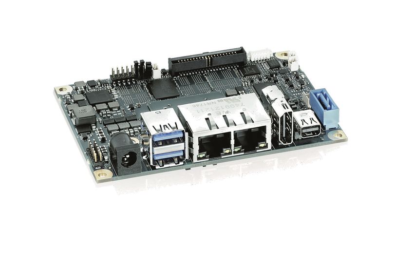
pITX-APL V2.0 – Rev. 1.3

Revision History

 Revision         Brief Description of Changes                  Date of Issue               Author
 1.0              Initial Issue                                 02. March 2020              hjs
 1.1              BSP Win7 removed                              06. April 2020              hjs
 1.2              Voltage pin 7 changed to 5 V in chapter       21. July 2020               hjs
                  6.14, M.2 issues updated in chapter 6.17
 1.3              Intel N4200 SKU added, Power Connector        17. August 2020             hjs
                  in chapter 6.8 changed, Standby Current
                  inserted

Intended Use
THIS DEVICE AND ASSOCIATED SOFTWARE ARE NOT DESIGNED, MANUFACTURED OR INTENDED FOR USE OR RESALE
FOR THE OPERATION OF NUCLEAR FACILITIES, THE NAVIGATION, CONTROL OR COMMUNICATION SYSTEMS FOR
AIRCRAFT OR OTHER TRANSPORTATION, AIR TRAFFIC CONTROL, LIFE SUPPORT OR LIFE SUSTAINING APPLICATIONS,
WEAPONS SYSTEMS, OR ANY OTHER APPLICATION IN A HAZARDOUS ENVIRONMENT, OR REQUIRING FAIL-SAFE
PERFORMANCE, OR IN WHICH THE FAILURE OF PRODUCTS COULD LEAD DIRECTLY TO DEATH, PERSONAL INJURY, OR
SEVERE PHYSICAL OR ENVIRONMENTAL DAMAGE (COLLECTIVELY, "HIGH RISK APPLICATIONS").
You understand and agree that your use of Kontron devices as a component in High Risk Applications is entirely at
your risk. To minimize the risks associated with your products and applications, you should provide adequate design
and operating safeguards. You are solely responsible for compliance with all legal, regulatory, safety, and security
related requirements concerning your products. You are responsible to ensure that your systems (and any Kontron
hardware or software components incorporated in your systems) meet all applicable requirements. Unless
otherwise stated in the product documentation, the Kontron device is not provided with error-tolerance capabilities
and cannot therefore be deemed as being engineered, manufactured or setup to be compliant for implementation or
for resale as device in High Risk Applications. All application and safety related information in this document
(including application descriptions, suggested safety measures, suggested Kontron products, and other materials) is
provided for reference only.

                    Handling and operation of the product is permitted only for trained personnel within a work
                    place that is access controlled. Please follow the “General Safety Instructions for IT
                    Equipment” supplied with the system.

                                                                        www.kontron.com                          // 4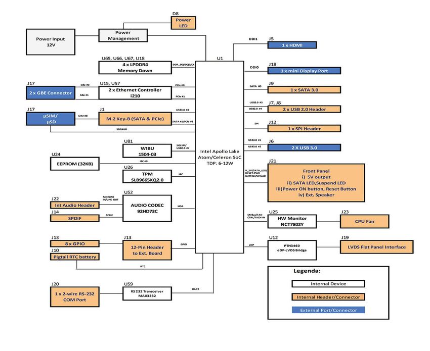
pITX-APL V2.0 – Rev. 1.3

Customer Support
Find Kontron contacts by visiting: http://www.kontron.com/support.

Customer Service
As a trusted technology innovator and global solutions provider, Kontron extends its embedded market strengths
into a services portfolio allowing companies to break the barriers of traditional product lifecycles. Proven product
expertise coupled with collaborative and highly-experienced support enables Kontron to provide exceptional peace
of mind to build and maintain successful products.
For more details on Kontron’s service offerings such as: enhanced repair services, extended warranty, Kontron
training academy, and more visit http://www.kontron.com/support-and-services/services.

Customer Comments
If you have any difficulties using this user guide, discover an error, or just want to provide some feedback, contact
Kontron support. Detail any errors you find. We will correct the errors or problems as soon as possible and post the
revised user guide on our website.

Terms and Conditions
Kontron warrants products in accordance with defined regional warranty periods. For more information about
warranty compliance and conformity, and the warranty period in your region, visit http://www.kontron.com/terms-
and-conditions.
Kontron sells products worldwide and declares regional General Terms & Conditions of Sale, and Purchase Order
Terms & Conditions. Visit http://www.kontron.com/terms-and-conditions.
For contact information, refer to the corporate offices contact information on the last page of this user guide or visit
our website CONTACT US.

                                                                          www.kontron.com                             // 5
pITX-APL V2.0 – Rev. 1.3

Symbols
The following symbols may be used in this manual

                   DANGER indicates a hazardous situation which, if not avoided,
                   will result in death or serious injury.

                   WARNING indicates a hazardous situation which, if not avoided,
                   could result in death or serious injury.

                   CAUTION indicates a hazardous situation which, if not avoided,
                   may result in minor or moderate injury.

                   NOTICE indicates a property damage message.

                   Electric Shock!
                   This symbol and title warn of hazards due to electrical shocks (> 60 V) when touching
                   products or parts of them. Failure to observe the precautions indicated and/or prescribed by
                   the law may endanger your life/health and/or result in damage to your material.
                   Please refer also to the "High-Voltage Safety Instructions" portion below in this section.

                   ESD Sensitive Device!
                   This symbol and title inform that the electronic boards and their components are sensitive
                   to static electricity. Care must therefore be taken during all handling operations and
                   inspections of this product in order to ensure product integrity at all times.

                   HOT Surface!
                   Do NOT touch! Allow to cool before servicing.

                   Laser!
                   This symbol inform of the risk of exposure to laser beam and light emitting devices (LEDs)
                   from an electrical device. Eye protection per manufacturer notice shall review before
                   servicing.

                   This symbol indicates general information about the product and the user manual.
                   This symbol also indicates detail information about the specific product configuration.

                   This symbol precedes helpful hints and tips for daily use.

                                                                       www.kontron.com                           // 6
pITX-APL V2.0 – Rev. 1.3

Table of Contents
Symbols .................................................................................................................................................................................................................6
Table of Contents ............................................................................................................................................................................................... 7
List of Tables....................................................................................................................................................................................................... 8
List of Figures ......................................................................................................................................................................................................9
1/           Introduction ..........................................................................................................................................................................................10
2/           Description.............................................................................................................................................................................................11
2.1. Configurations ............................................................................................................................................................................................ 12
2.2. Accessories List ........................................................................................................................................................................................ 13
3/           Installation procedure ......................................................................................................................................................................14
3.1. Installing the Board ..................................................................................................................................................................................14
3.2. Requirements IEC60950-1 ..................................................................................................................................................................... 15
3.3. Lithium battery precautions ................................................................................................................................................................. 15
4/           System specifications ....................................................................................................................................................................... 16
4.1. Block Diagram ............................................................................................................................................................................................ 16
4.2. Component Main Data ............................................................................................................................................................................ 17
5/           Jumpers and Connectors ................................................................................................................................................................ 22
5.1. Hardware Configuration Setting ......................................................................................................................................................... 22
5.1.1. Jumpers and Connectors..................................................................................................................................................................... 22
5.2. Mainboard Placement and Rear I/O locations............................................................................................................................... 23
5.2.1. Rear Side .................................................................................................................................................................................................. 25
6/           Pin Definitions..................................................................................................................................................................................... 26
6.1. Processor Support ................................................................................................................................................................................... 27
6.2. System Memory Support ...................................................................................................................................................................... 27
6.3. MicroSD and MicroSIM........................................................................................................................................................................... 28
6.4. Ethernet Connectors (I/O area) .......................................................................................................................................................... 29
6.5. USB Connectors (I/O area) ................................................................................................................................................................... 30
6.6. Fan Connector (internal, J23) .............................................................................................................................................................. 32
6.7. DC Power Jack Connector (12 Vin Ext., J11) ....................................................................................................................................... 33
6.8. Internal Power Connector (Vin Int., J4) ............................................................................................................................................ 34
6.9. Front Panel (FP) internal (J21) ............................................................................................................................................................. 34
6.10. USB internal (J7, J8)............................................................................................................................................................................... 35
6.11. SBC Connector (GPIO and Ext. Battery) (internal, J13)) .............................................................................................................. 35
6.12. Jumper Load BIOS Default and Clear CMOS (J15) ........................................................................................................................ 36
6.13. Jumper Autostart (J3) ........................................................................................................................................................................... 37
6.14. LVDS (internal, J19)................................................................................................................................................................................ 37
6.15. SATA (Serial ATA) Disk Interfaces (internal, J9)........................................................................................................................... 39
6.16. Mini DisplayPort .....................................................................................................................................................................................40
6.17. M.2 B-Key Slot Connector (J1) .............................................................................................................................................................41
6.18. Serial COM (J20) ..................................................................................................................................................................................... 43
6.19. Front Panel Audio Connector (J22) .................................................................................................................................................. 43
6.20. BIOS Recovery Connector (J12) .........................................................................................................................................................44
6.21. S/PDIF Connector (J14) ........................................................................................................................................................................44
7/           Installation and Power Considerations ...................................................................................................................................... 45
7.1. Hardware Monitor .................................................................................................................................................................................... 45
7.2. Real-Time Clock ....................................................................................................................................................................................... 45
7.3. Onboard Power Supply .......................................................................................................................................................................... 45
7.4. External Power Supply .......................................................................................................................................................................... 45

                                                                                                                                        www.kontron.com                                                             // 7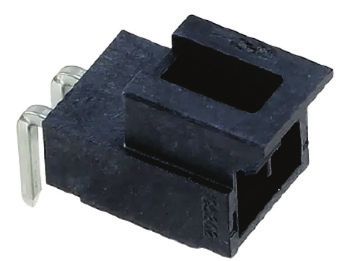
pITX-APL V2.0 – Rev. 1.3

7.5. Power Management ............................................................................................................................................................................... 46
8/          uEFI BIOS............................................................................................................................................................................................... 47
8.1. Starting the uEFI BIOS............................................................................................................................................................................. 47
8.2. Setup Menus .............................................................................................................................................................................................48
8.2.1. Main Setup Menu ..................................................................................................................................................................................48
8.2.2. Advanced Setup Menu ....................................................................................................................................................................... 50
8.2.3. Chipset Setup Menu ............................................................................................................................................................................ 55
8.2.4. Security Setup Menu........................................................................................................................................................................... 58
8.2.4.1. Remember the Password............................................................................................................................................................... 59
8.2.5. Boot Setup Menu .................................................................................................................................................................................. 60
8.2.6. Exit Setup Menu ................................................................................................................................................................................... 62
8.3. The uEFI Shell ........................................................................................................................................................................................... 63
8.3.1. Basic Operation of the uEFI Shell .................................................................................................................................................... 63
8.3.1.1. Entering the uEFI Shell ..................................................................................................................................................................... 63
8.3.1.2. Exiting the uEFI Shell........................................................................................................................................................................ 63
8.4. uEFI Shell Scripting ................................................................................................................................................................................. 64
8.4.1. Startup Scripting................................................................................................................................................................................... 64
8.4.2. Create a Startup Script....................................................................................................................................................................... 64
8.4.3. Examples of Startup Scripts ............................................................................................................................................................ 64
8.4.3.1. Execute Shell Script on other Harddrive ................................................................................................................................... 64
8.5. Firmware Update..................................................................................................................................................................................... 64
8.5.1. Updating Procedure ............................................................................................................................................................................. 64
9/          Technical Support ............................................................................................................................................................................. 66
9.1. Warranty ..................................................................................................................................................................................................... 66
9.2. Returning Defective Merchandise ..................................................................................................................................................... 66
List of Acronyms .............................................................................................................................................................................................. 68
About Kontron .................................................................................................................................................................................................. 69

List of Tables
Table 1: Component Product Numbers...................................................................................................................................................... 12
Table 2: List of Accessories ........................................................................................................................................................................... 13
Table 3: List of Cooling Solutions ................................................................................................................................................................ 13
Table 4: List of Miscellaneous Parts .......................................................................................................................................................... 13
Table 5: Component Main Data.................................................................................................................................................................... 17
Table 6: Environmental Conditions ........................................................................................................................................................... 20
Table 7: Connector Definitions .................................................................................................................................................................... 26
Table 8: Processor Support.......................................................................................................................................................................... 27
Table 9: Memory Support ............................................................................................................................................................................. 27
Table 10: Pin Assignment MicroSIM .......................................................................................................................................................... 28
Table 11: Pin Assignment MicroSD ............................................................................................................................................................. 28
Table 12: Pin Assignment .............................................................................................................................................................................. 29
Table 13: Signal Description ......................................................................................................................................................................... 30
Table 14: Pin Assignment .............................................................................................................................................................................. 30
Table 15: Signal Description ......................................................................................................................................................................... 30
Table 16: 3-pin Mode ...................................................................................................................................................................................... 32
Table 17: Signal Description ......................................................................................................................................................................... 32
Table 18: Internal Power Connector .......................................................................................................................................................... 34
Table 19: FP Connection ................................................................................................................................................................................. 34
Table 20: USB Internal Connection ............................................................................................................................................................ 35
Table 21: Pinout SBC Connector .................................................................................................................................................................. 35
Table 22: CMOS Internal Connection......................................................................................................................................................... 36

                                                                                                                                      www.kontron.com                                                            // 8
pITX-APL V2.0 – Rev. 1.3
Table 23: Always ON Internal Connection ............................................................................................................................................... 37
Table 24: LVDS Pin Assignment .................................................................................................................................................................. 37
Table 25: Pin Assignment.............................................................................................................................................................................. 39
Table 26: Signal Description ........................................................................................................................................................................ 39
Table 27: MiniDisplay Port ............................................................................................................................................................................40
Table 28: Pin Assignment mPCIe .................................................................................................................................................................41
Table 29: Pin Assignment Serial COM ....................................................................................................................................................... 43
Table 30: Pin Assignment Audio Connector............................................................................................................................................ 43
Table 31: BIOS Recovery Connector ...........................................................................................................................................................44
Table 32: S/PDIF Connector .........................................................................................................................................................................44
Table 33: Power Management .................................................................................................................................................................... 46
Table 34: Navigation Hot Keys Available in the Legend Bar ............................................................................................................. 47
Table 35: Main Setup Menu Sub-screens ................................................................................................................................................ 49
Table 36: Advanced Setup menu Sub-screens and Functions .......................................................................................................... 51
Table 37: Chipset Setup menu Sub-screens and Functions .............................................................................................................. 55
Table 38: Security Setup Menu Functions............................................................................................................................................... 58
Table 39: Boot Setup Menu Functions...................................................................................................................................................... 60
Table 40: Save and Exit Setup Menu Functions .................................................................................................................................... 62
List of Figures
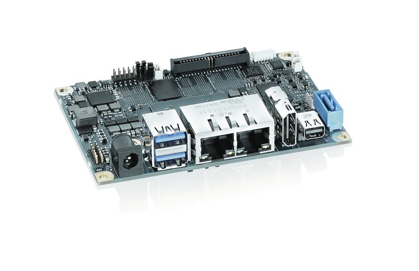
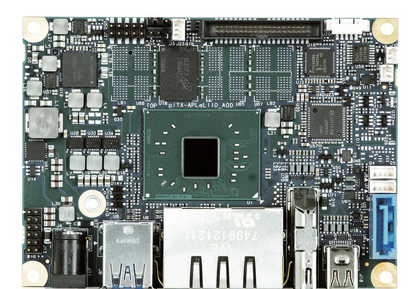
Figure 1: pITX-APL V2.0 board ......................................................................................................................................................................10
Figure 2: Premounted System with Pigtail Modul ................................................................................................................................. 12
Figure 3: Block Diagram.................................................................................................................................................................................. 16
Figure 4: Front Side and Interfaces ........................................................................................................................................................... 23
Figure 5: Rear Side ........................................................................................................................................................................................... 25
Figure 6: Pigtail Battery ................................................................................................................................................................................. 25
Figure 7: Combo Connector for MicroSD and MicroSIM...................................................................................................................... 28
Figure 8: Ethernet Connector ...................................................................................................................................................................... 29
Figure 9: USB 2.0/3.0 socket........................................................................................................................................................................ 30
Figure 10: USB 2.0 High Speed Cable .......................................................................................................................................................... 31
Figure 11: USB 3.0 High Speed Cable ........................................................................................................................................................... 31
Figure 12: 3-pin Fan Connector ................................................................................................................................................................... 32
Figure 13: Power Jack Connector ................................................................................................................................................................ 33
Figure 14: Internal Power Connector......................................................................................................................................................... 34
Figure 15: FP Connector ................................................................................................................................................................................. 34
Figure 16: USB Internal Connector ............................................................................................................................................................. 35
Figure 17: SBC Connector ............................................................................................................................................................................... 35
Figure 18: CMOS Internal Connector.......................................................................................................................................................... 36
Figure 19: Autostart......................................................................................................................................................................................... 37
Figure 20: LVDS Connector ........................................................................................................................................................................... 37
Figure 21: SATA Connector ............................................................................................................................................................................ 39
Figure 22: Available Cable Kits .................................................................................................................................................................... 39
Figure 23: Mini DisplayPort ..........................................................................................................................................................................40
Figure 24: M.2 Slot Connector ......................................................................................................................................................................41
Figure 25: Serial COM ..................................................................................................................................................................................... 43
Figure 26: Audio Connector .......................................................................................................................................................................... 43
Figure 27: BIOS Recovery Connector .........................................................................................................................................................44
Figure 28: S/PDIF Connector .......................................................................................................................................................................44
Figure 29: Real-Time Clock........................................................................................................................................................................... 45
Figure 30: Main Setup Menu Initial Screen .............................................................................................................................................48
Figure 31: Advanced Setup Menu Initial Screen ..................................................................................................................................... 50
Figure 32: Chipset Setup Menu Initial Screen......................................................................................................................................... 55
Figure 33: Security Setup Menu Initial Screen ....................................................................................................................................... 58
Figure 34: Boot Setup Menu Initial Screen .............................................................................................................................................. 60
Figure 35: Save and Exit Setup Menu Initial Screen ............................................................................................................................. 62
www.kontron.com // 9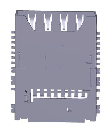
pITX-APL V2.0 – Rev. 1.3
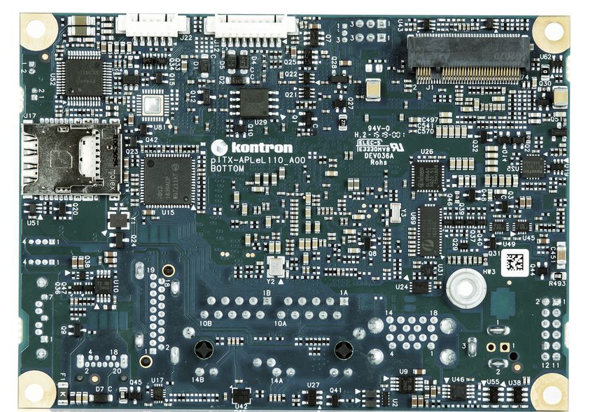
1/ Introduction
This manual describes the pico-ITX board with Intel CPU. This board will also be denoted pITX-APL V2.0 within this
Users Guide.
The use of this Users Guide implies a basic knowledge of PC hard- and software. This manual is focussed on
describing the pITX-APL V2.0 board’s special features and is not intended to be a standard PC textbook.
New users are recommended to study the short installation procedure stated in the following chapter before
switching-on the power.
All configuration and setup of the CPU board is either done automatically or manually by the user via the BIOS setup
menus.
Latest revision of this manual, datasheet, BIOS, drivers, BSPs (Board Support Packages) can be downloaded from
Kontron Web Page.
Figure 1: pITX-APL V2.0 board
www.kontron.com // 10pITX-APL V2.0 – Rev. 1.3
2/ Description
The board is based on the Intel System on Chip (SoC) and is mechanically compliant to the Pico-ITX (pITX)
specification. Board key features are:
4x channel LPDDR4, support maximum memory size up to 16 GB
1x Mini DisplayPort Rear Connector
1x HDMI
1x 24-bit Dual-Channel LVDS Converter for External Display with 12 V Backlight power output support
2x 10/100/1000 Gigabit LAN Rear Port
1x Dual-Stacked USB 3.0 Rear Port
2x Internal USB 2.0 headers
1x M.2 B-Key half-size connector for 2242 and 3042 modules
1x SATA Gen3 (up to 6 GB/s) connector
1x 2-wire RS-232 Serial Port internal header
1x Internal SPI Interface for external device
HD Audio with Microphone, Stereo Line-in & Stereo Line-out internal header, S/PDIF
1x Internal Front Panel Header for LEDs, Power Buttons and PC Speaker
WIBU Secure Element (optional)
TPM 2.0
1x Internal Header for up to 10 configurable GPIOs
1x Fan connector for CPU
Temperature Sensor
+12 V DC Input via locking barrel-type connector or Internal Power Header
pITX form factor
1x Pigtail RTC battery
The pITX-APL V2.0 is part of the Security Solution Product Line. The motherboard is prepared for Application
Protection, License Creation, Delivery, Management and Tracking, Implementation of license models as well as the
assignment of privileges and access levels.
Typical Applications:
POS/POI: Higher Graphics and CPU core performance, Low power, multi display support,
Medical/Connectivity: Higher Graphics and CPU core performance
Industrial Automation: Wide range of I/Os, compact size, longevity
Digital signage: Multi display support, low power, wide range of I/Os
Future-oriented Devices: Display Port and LVDS, low power, compact size
Kiosk and PoS applications
www.kontron.com // 11pITX-APL V2.0 – Rev. 1.3
2.1. Configurations
Kontron offers the pITX-APL V2.0 in different configurations. The products can be ordered in different flavors.
Table 1: Component Product Numbers
Product Number Description MTBF (hours)
44012-0200-23-2 Intel® Mobile Celeron® N3350 2C 2.3 GHz, 6 W, 1,571,585
Commercial temp, 2 GB RAM ,Entry
44012-0800-20-4 Intel® Atom™ x7 E3950 4C 2.0 GHz, 13 W, 1,577,287
Industrial temp, 8 GB RAM, High
44012-0400-18-4 Intel® Atom™ x5 E3940 4C 1.8 GHz, 9,5W, 1,577,287
Industrial temp, 4 GB RAM, Intermediate
44012-0200-18-2 Intel® Atom™ x5 E3930 2C 1.8 GHz, 6,5W, 1,577,287
Industrial temp, 2 GB RAM, Entry
44012-0800-15-4 Intel® Celeron® J3455 4C 2.3 GHz, 10 W, 1,571,585
Commercial Temp, 8 GB RAM, Entry
44012-1600-15-5 Intel® Celeron® J3455 4C 2.3 GHz, 6 W, 1,571,585
Commercial, 16 GB RAM, Entry
44012-0800-25-4 Intel® Pentium® Processor N4200 4C 2.5 GHz, 1,571,585
6 W, Commercial, 8 GB RAM, Entry
Warning: If changing the premounted cooling system, then the system might get overheated
resulting in instable system or defects if the cooling system is insufficient.
Figure 2: Premounted System with Pigtail Modul
www.kontron.com // 12pITX-APL V2.0 – Rev. 1.3
2.2. Accessories List
Table 2: List of Accessories
Connector On-Board Connectors Mating Connectors/Cables
(RefDes) Manufacturer Part No. Manufacturer Part No.
Fan (J23) Molex 53047-0310 Molex 51021-0300
Kontron 1060-9200
SATA (J9) Lotes ABA-SAT-010-K08 Kontron 96079-0000-00-1
Audio (J22) Molex 53261-0671 Molex 51021-0600
Kontron 96063-0000-00-1
DC Jack (J11) TE Connectivity 2132230-2 TE Connectivity 1744417-2
Internal Power Molex 105313-1102 Molex 1053071202
(J4)
LVDS (J19) Samtec SHF-120-01-F-D- Don Connex A32-40-C-G-B-1
SM-K-TR
Pinrex 53C-90-40GBE0 Pinrex 977-31-403204
Kontron 821515
Serial COM (J20) Molex 53261-0571 Molex 51021-0500
Kontron 1055-8059
SPI (J12) Molex 53261-0971 Molex 51021-0900
GPIO (Battery Molex 53261-1071 Molex 51021-1000
Module) Kontron 1055-8063
GPIO (J13) Molex 87758-1216 Molex 79107-7205
Kontron 1055-7645
Front Panel (J21) Molex 87759-1014 Molex 51110-1050
Amphenol-FCI 57202-F52-06LF Kontron 1055-8065
USB2.0 (J7, J8) Molex 53047-0410 Molex 51021-0400
Kontron 96054-0000-00-2
RTC (J10) MOLEX 53047-0210 Contacthings CONT2032
Solution
Table 3: List of Cooling Solutions
Cooling Solutions Part No.
Active Cooling Solution (MTG1-4) 1064-7834
Passive Cooling Solution (MTG1-4) 1065-0044
Table 4: List of Miscellaneous Parts
Miscellaneous Parts Part No.
Custom Y-cable for 2.5" drives 1066-8838
(5V/GND, J7,J8)
www.kontron.com // 13pITX-APL V2.0 – Rev. 1.3
3/ Installation procedure
3.1. Installing the Board
ESD Sensitive Device!
Electrostatic discharge (ESD) can damage equipment and impair electrical circuitry.
• Wear ESD-protective clothing and shoes
• Wear an ESD-preventive wrist strap attached to a good earth ground
• Check the resistance value of the wrist strap periodically (OK: 1 MΩ to 10 MΩ)
• Transport and store the board in its antistatic bag
• Handle the board at an approved ESD workstation
• Handle the board only by the edges
To get the board running follow these steps. If the board shipped from Kontron has already components like RAM
and CPU cooler mounted, then relevant steps below can be skipped.
1. Turn off the PSU (Power Supply Unit)
Turn off PSU (Power Supply Unit) completely (no mains power connected to the PSU)
or leave the Power Connectors unconnected while configuring the board. Otherwise
components (RAM, LAN cards etc.) might get damaged. Make sure to use +12 V single supply
only. Alternatively use a standard ATX PSU with suitable cable kit and PS_ON# active.
2. Insert the memory module
Be careful to push it in the slot(s) before locking the tabs. For a list of approved memory modules contact your
Distributor or FAE. See also chapter “System Memory Support”. Use memory modules with the same density in
all sockets!
3. Cooler Installation
Normally the cooler is premounted, but in case not, then make sure that the heat paste etc. on the cooler is
intact and cover the full area of the SoC. Connect cooler fan electrically to the FAN_CPU connector.
4. Connecting Interfaces
Insert all external cables for hard disk, keyboard etc. A monitor must be connected in order to change BIOS
settings.
5. Connect and turn on PSU
Connect PSU to the board by the ATX +12 V power adapter to the rear DC jack.
6. BIOS Setup
Enter the BIOS setup by pressing the key during boot up.
Enter “Exit Menu” and load Setup Defaults.
Refer to the “BIOS Configuration/Setup“ section of this manual for details on BIOS setup.
To clear all BIOS settings, including Password protection, activate “Load Default BIOS
Settings” Jumper for > 10 sec (without power connected).
7. Mounting the board in chassis
When mounting the board to chassis etc. please notice that the board contains components
on both sides of the PCB which can easily be damaged if board is handled without
reasonable care. A damaged component can result in malfunction or no function at all.
www.kontron.com // 14pITX-APL V2.0 – Rev. 1.3
When fixing the Motherboard on a chassis it is recommended to use screws with integrated washer and a
diameter of > 7 mm. Do not use washers with teeth, as they can damage the PCB and cause short circuits.
3.2. Requirements IEC60950-1
Take care when designing chassis interface connectors in order to fulfil the IEC60950-1 standard. Users of pITX-APL
V2.0 must evaluate the end product to ensure compliance the requirements of the IEC60950-1 safety standard are
met:
The motherboard must be installed in a suitable mechanical, electrical and fire enclosure.
The system in its enclosure must be evaluated for temperature and air flow considerations.
The motherboard must be powered by a CSA or UL approved power supply that limits the maximum input
current to 6 A to an external 12 V locking barrel-type DC jack or to an internal 12 V 2-pin DC power
connector.
For interfaces having a power pin such as external power or fan, ensure that the connectors and wires are
suitably rated. All connections from/to the product shall be with SELV circuits only.
Wires have suitable rating to withstand the maximum available power.
The enclosure of the peripheral device fulfils the fire protecting requirements of IEC60950-1.
3.3. Lithium battery precautions
Danger of explosion if the lithium battery is incorrectly replaced.
• Replace only with the same or equivalent type recommended by the manufacturer
• Dispose of used batteries according to the manufacturer’s instructions
VORSICHT! Explosionsgefahr bei unsachgemäßem Austausch der Batterie.
• Ersatz nur durch denselben oder einen vom Hersteller empfohlenen Typ
• Entsorgung gebrauchter Batterien nach Angaben des Herstellers
ATTENTION! Risque d'explosion avec l'échange inadéquat de la batterie.
• Remplacement seulement par le même ou un type équivalent recommandé par le
producteur
• L'évacuation des batteries usagées conformément à des indications du fabricant
PRECAUCION! Peligro de explosión si la batería se sustituye incorrectamente.
• Sustituya solamente por el mismo o tipo equivalente recomendado por el fabricante
• Disponga las baterías usadas según las instrucciones del fabricante
ADVARSEL! Lithiumbatteri – Eksplosionsfare ved fejlagtig håndtering.
• Udskiftning må kun ske med batteri af samme fabrikat og type
• Levér det brugte batteri tilbage til leverandøren.
ADVARSEL! Eksplosjonsfare ved feilaktig skifte av batteri.
• Benytt samme batteritype eller en tilsvarende type anbefalt av apparatfabrikanten.
• Brukte batterier kasseres i henhold til fabrikantens instruksjoner
VARNING! Explosionsfara vid felaktigt batteribyte.
• Använd samma batterityp eller en ekvivalent typ som rekommenderas av
apparattillverkaren.
• Kassera använt batteri enligt fabrikantens instruktion.
VAROITUS! Paristo voi räjähtää, jos se on virheellisesti asennettu.
• Vaihda paristo ainoastaan lalteval- mistajan suosittelemaan tyyppiln
• Hävitä käytetty paristo valmistajan ohjeiden mukaisesti
www.kontron.com // 15pITX-APL V2.0 – Rev. 1.3
4/ System specifications
4.1. Block Diagram
Figure 3: Block Diagram
www.kontron.com // 16pITX-APL V2.0 – Rev. 1.3
4.2. Component Main Data
The table below summarizes the features of the pITX-APL V2.0 embedded motherboard.
Table 5: Component Main Data
Motherboard pITX-APL
Form factor Pico-ITX (100 mm by 72 mm by 1.6 mm/Length x Width x Thickness)
Mechanical 100 mm x 72 mm x 41 mm (Length x Width x Height)
Dimensions with
cooling solution
Processor Onboard CPU variants
Intel® Processor line, 14 nm SoC
Intel® Atom™ x7 E3950 4C 2.0 GHz, 13 W
Intel® Atom™ x5 E3940 4C 1.8 GHz, 9.5 W
Intel® Atom™ x5 E3930 2C 1.8 GHz, 6.5 W
Intel® Celeron® N3350 2C 2.3 GHz, 6 W
Intel® Celeron® Processor J3455 2.3GHz, 10 W
Intel® Pentium® Processor N4200, 4 Cores, 2.5 GHz, 6 W
BIOS AMI Aptio V
EEPROM Atmel AT24C32 for board information
Memory 4x channel LPDDR4, support maximum memory size up to 16 GB
Flash Memory The pITX-APL V2.0 board supports microSD cards via onboard microSD/microSIM combo
connector. The microSD card interface is sharing a combo connector with the micro SIM
card.
Storage The pITX-APL V2.0 supports one SATA Gen 3 port.
Wake On Wake on LAN, USB, Power button (S3 to S5)
Hardware Status The hardware monitoring chip NCT7802Y is connected via SMBus and incorporates the
Monitor following features:
CPU Temperature Monitoring
Voltages Level
Fan Control
TPM Infineon SLB9665XQ2.0
Power ACPI 5.0 support:
management Processor Core C-States (CC0, CC1, CC6)
Processor Core/Package States support (C0, C1, C1E, C6, C6L, C7, C8, C9, C10)
Processor Module States (MC0-CC0, MC0-CC6, MC7)
Display States support (D0, D1, D2, D3, D4, D5, D9)
Graphics States (RC0, RC1, RC6)
System Sleep States (S0, S0ix, S3, S4, S5)
Dynamic I/O power reduction (disabling sense amps on input buffers, tri-stating
output buffers)
Active power-down of Display links
Battery BR2032 Pigtail Battery
See Safety Instructions below this table!
Expansion 1x M.2 for 2242 and 3042 modules (PCIe Rev 2.0), SATA Gen 3.0
www.kontron.com // 17pITX-APL V2.0 – Rev. 1.3
Operating System Six different Board Support Packages are offered:
Support BSP1: Windows 10 IOT Enterprise 64 bit, eMMC Boot
BSP2: Windows 10 IOT Core, Redstone 64 bit
BSP3: Linux 64 bit, Yocto
BSP4: VxWorks 7.x or newer (optional)
API: KEAPI 3 for all OS (except for VxWorks)
External I/O
LAN, USB3.0 2x RJ-45 LAN Ports and dual USB3.0
Graphics 1x Mini DisplayPort Rear Connector, 1x HDMI
Power 12 V DC-IN Power Jack
Internal I/O
SATA 1x SATA Gen 3 straight with Locking Latch
USB 2.0 2x USB 2.0 4-pin header
Serial Peripheral 1x internal 9-pin header
Interface (SPI)
LVDS 1x 24-bit Dual-Channel LVDS Converter for External Display with 3.3 V/5 V Backlight power
output support
M.2 B-Key 1x M.2 B-Key for 2242 and 3042 modules half-size connector with SIM Card Interface, NGFF
SATA SSD and USB3.0/2.0
Audio HD Audio with Microphone, Stereo Line-in & Stereo Line-out internal header, SPDIF
Serial 1x RS232
Internal Header
Power Locking barrel-type DC Power Jack
internal 2-pin Power connector (optional)
CPU Fan 1x 1.25 mm 3-pin CPU Fan connector
CMOS 2x (1x 3 ) 2 mm pin-header
Clear/Autostart
Front Panel 1x (2x 5) 2 mm pin connector
MicroSD/microSIM microSD & microSIM combo socket adapter
www.kontron.com // 18pITX-APL V2.0 – Rev. 1.3
Display
Display Interface 1x HDMI, 1x miniDisplay Port and 1x LVDS internal
Note: Three independent Displays Max.
Resolution max 4096x2304 @ 60 Hz, 24 bpp (One panel display)
Ethernet
Controller Intel i210/i211
Interface IEEE 802.3 10BASE-T / 100BASE-TX / 1000BASE-T compliant
Audio
Universal Audio The onboard audio codec supports High Definition Audio with UAA (Universal Audio
Architecture (UAA) Architecture). The following connections are available via an internal header:
Stereo Line-Out
Stereo Line-in
Mono Microphone-in
Power
External Power The pITX-APL V2.0 is operated by a single 12 V DC supply via a locking Barrel-type jack or
Supply through an internal 2-pin header.
Danger of explosion if the lithium battery is incorrectly replaced.
• Replace only with the same or equivalent type recommended by the manufacturer
• Dispose of used batteries according to the manufacturer’s instructions
www.kontron.com // 19pITX-APL V2.0 – Rev. 1.3
Table 6: Environmental Conditions
Operating It is the customer’s responsibility to provide sufficient airflow around each of the
components to keep them within allowed temperature range. The board has two
temperature ranges:
commercial grade: 0°C to +60°C (32°F~140°F) operating temperature (forced
cooling).
extended grade: -25°C to +75°C (-13°F~167°F) operating temperature (SKU
Dependent and with standard cooler running at maximum speed)
DC Voltage Limits: ±5 % of nominal voltage.
10 % to 95 % relative humidity non-condensing at temperature of 25°C to 30°C
Storage -40°C to 85°C (-40°F to 185°F); lower limit of storage temperature is defined by
specification restriction of on-board BR2032 battery.
Up to 95 % relative humidity (temperature 25°C to 30°C)
Thermal ramps: 4 cycles between limits at a rate of ≤ 20°C per hour
Temperature extremes: 36 nonconsecutive hours at high limit
24 nonconsecutive hours at low limit
Radiated Emissions All Peripheral interfaces intended for connection to external equipment are EMI protected.
(EMI) Compliant to the requirements of:
EN55032 Class B radiated and conducted
Immunity Includes following tests accordingly:
IEC 61000 PT4-2, (EN 61000-4-2) Electrostatic discharge immunity ESD
IEC 61000 PT4-3, (EN 61000-4-3 and ENV 50204) Radiated Field
IEC 61000 PT4-4, (EN 61000-4-4) Electrical fast transient/burst (EFT) BURST
IEC 61000 PT4-5, (EN 61000-4-5) Surge immunity test
IEC 61000 PT4-6, (EN 61000-4-6) Immunity to conducted disturbances
IEC 61000 PT4-8, (EN 61000-4-8) Immunity to magnetic fields (LOW)
REACH Regulation (EC) No 1907/2006
Safety IEC 62368-1: Safety for information technology equipment including electrical business
equipment
Shock Conducted in standard available ATX chassis. Test is following Standard IEC 60068-2-27,
half-sine wave, Acceleration 2 g, Pulse duration:11 ms. Number of shocks: 600 shocks
(100 shocks for each face.)
Bump IEC 60068-2-27: Half Sine Waveform Acceleration 2 g; Pulse Duration 11 ms. Number of
shocks: 600 shocks (100 shocks for each face.)
Vibration AW IEC 60068-2-64, test Fh, Random Vibration, 90 min per axis, 3 axes at 1.9 grms, with
PSD: 10-20Hz: 0.05 g²/Hz and 20-500Hz:- 3dB/octave.
MTBF 43.800 hours depending on processor type and according to Telcordia standard SR-332
Issue 3 at 30°C
Restriction of The product will comply to the European Council Directive on the approximation of the laws
Hazardous of the member states relating to Directive 20011/65/EU or the last status thereof.
Substances
(RoHS II)
Altitude 2000 m max., optionally 3000 m
www.kontron.com // 20You can also read