SX4 Optical Sub Assembly Fiber Optic Components - Data Sheet, Reference Design and Evaluation Kit Manual
←
→
Page content transcription
If your browser does not render page correctly, please read the page content below
SX4 Optical Sub Assembly
             Data Sheet, Reference Design and Evaluation Kit Manual

                     Fiber Optic
                    Components

                                       1

DataSheets.indd 1                                                3/13/07 7:50:31 PM
P1TX4A-SX4 Data Sheet

                                                                     5.0          Electrical Specifications
                                                                     Parameter                                Symbol    Min      Type    Max       Units
                                                                     Input Differential Impedance                                100               ohm
                                                                     Data Rate per Wavelength
                                                                                                           SX4-Tx-01v
                                                                                                           SX4-Tx-01d           0.1552
                                                                     0.1552
                                                                     1.6
                                                                     3.125                                     Gb/s
                                                                     Run Length                                                           80
    1.0          Description                                         Transmit Differential Input Voltage                400              1600     mVp-p

    The TxSX4 is an optical subassembly (OSA)
    that transmits four video- or data-channels over                 6.0          Optical Characteristics
    one multimode fiber. Each channel is capable
                                                                     Parameter                                Symbol    Min      Type    Max       Units
    of transmitting up to 3.125Gbps. With the driver                 “Peak Optical Power, per Channel4”        Pout                       1        dBm
    embedded in the OSA and a ZIF-terminated                         Optical Modulation Amplitude per ch                -6.25                      dBm
    flex circuit, the TxSX4 is a fully integrated TOSA               Wavelength Range                                   771.5            856.5      nm
                                                                     Center Wavelength – Lane 0                         771.5    778     784.5      nm
    versatile enough to be designed in to a variety of
                                                                     Center Wavelength – Lane 2                         793.5    800     806.5      nm
    systems.                                                         Center Wavelength – Lane 2                         818.5    825     831.5      nm
                                                                     Center Wavelength – Lane 3                         843.5    850     856.5      nm
    2.0          Features                                            RMS Spectral Width                                                   0.5       nm
                                                                     Optical Rise/Fall Time5                                              110       ps
                 •     4 optical channels over one multimode fiber
                 •     On-board Laser Driver                         7.0          Optical Performance Specifications
                 •     Low-stress, highly flexible connection
                                                                     Parameter                                          Min      Type    Max      Units
                 •     Low power consumption                         Fiber Length - 62.5m Enhanced (1000 MHz*km)6
                 •     300m – 1000m transmission distance                                   SX4-Tx-01v                   2               1000
                                                                                            SX4-Tx-01d                   2               500        m
                 •     LVPECL input                                  Fiber Length - 50m Standard (500 MHz*km)6
                                                                                            SX4-Tx-01v                   2               400
                                                                                            SX4-Tx-01d                   2               300        m
                                                                           Fiber Length - 62.5m Legacy (160 MHz*km) 6
                              Four SW VCSEL                  SC                             SX4-Tx-01v                   2               200
                                                                                            SX4-Tx-01d                   2               100        m
                              Quad Laser Driver
                                                                         Measured at the end of a 2m section of 62.5μ fiber. The maximum and
                                                                             minimum of the allowed range of average transmitter power per
                                                                             channel coupled into the fiber are worst-case values to account for
    3.0          Absolute Maximum Ratings                                    manufacturing variances and drift due to temperature.
                                                                         Rise and fall times measured from 20 - 80%
    Parameter                       Symbol    Min Typ Max Units          Max distance considers the theoretical worst-case conditions. Actual
    Storage Temperature1              Tst     -40     85 °C                  distance may be up to 4x specified distance.
    3.3 Volt Supply1                Vcc-Vee   -0.3    3.6  V
    Relative Humidity2                RH       8       80  %
    Electrostatic Discharge          ESD              400 V

    4.0          Recommended Operating
                 Conditions
    Parameter                            Symbol Min Typ Max Units
    “Ceramic (substrate) Temperature 1,3” Ta      0        70 °C
    3.3 Volt Supply                      Vcc-Vee 3.15     3.45 V
    3.3 Volt Supply Current                Icc        260 293 mA

                                                                     2

DataSheets.indd 2                                                                                                                                3/13/07 7:50:36 PM
P1TX4A-SX4 Data Sheet

     8.0           Pin Numbers and Descriptions                                                        9.0     Dimensions
     The TxSX4 plugs into a 27 pin zero insertion                                                       Exposed traces for ZIF connector

     force (ZIF) connector. For information on the
     specifications of the connector,
     contact either Molex (P/N
     52931-2790) or Hirose (P/N
                                                                                                                     Heat-sinked towards
     FH18-27S-0.3SHW).                                                                                                  top of Module

                                                                                                        Surface Temp Measurement Point
             Underside of board with ZIF connector
                           (OSAs shown unfolded)

                                                          Pin #              Signal        Name
     Description
              1      VCC            Voltage Input                       +3.3 volt input
              2      VCC            Voltage Input                       +3.3 volt input
              3      VCC            Voltage Input                       +3.3 volt input
              4       SEN           Serial Enable                  Enables the SCK AND SIO
              5      POR       Power On Reset Indicator
              6      SCK            Serial Clock             Reference clock for data thru SIO
              7      PORL      Power On Reset Latched
              8        EN              Enable                     “Enables the driver, typically
                                                                  wired-on with 3.3V and 10K
                                                                            Resistor”
             9        SIO          Serial Interface                 Bi-directional serial data
                                                                          input/output
            10        GND             Ground
            11        GND             Ground
            12         0          Ch 3 + Data Input           Positive differential input for
                                                                     850nm channel
            13         0          Ch 3 - Data Input           Negative differential input for
                                                                     850nm channel
            14        GND             Ground
            15        GND             Ground
            16         0          Ch 2 + Data Input           Positive differential input for
                                                                     825nm channel
            17         0          Ch 2 - Data Input           Negative differential input for
                                                                     825nm channel
            18        GND             Ground
            19        GND             Ground
            20         0          Ch 1 + Data Input           Positive differential input for
                                                                     800nm channel
            21         0          Ch 1 - Data Input           Negative differential input for
                                                                     800nm channel
            22       GND              Ground
            23       GND              Ground
            24       + IN0        Ch 0 + Data Input           Positive differential input for
                                                                     775nm channel
            25       - IN0        Ch 0 - Data Input           Negative differential input for
                                                                     775nm channel
            26        GND              Ground
            27        GND              Ground

                                                                                                   3

DataSheets.indd 3                                                                                                                          3/13/07 7:50:38 PM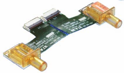
P1RX4A-SX4 Data Sheet

        1.0 Description
        The RxSX4 is an optical subassembly (OSA) that receives and separates
                                                                                          4.0          Recommended Operating
            up to four video- or data-channels from one singlemode or multimode
            fiber. With the TIA and Limiting Amp embedded in the OSA and a ZIF-
                                                                                                       Conditions
            terminated flex circuit, the RxSX4 is a fully integrated ROSA versatile
            enough to be designed in to a variety of systems.                             Parameter                                Symbol     Min      Typ      Max       Units
        2.0 Features
                                                                                          Data Rate                                  DR      0.1552             1.6       Gbps
        • 4 optical channels
        • Singlemode or Multimode                                                         SX4-Rx-01v                                         0.1552            3.125
        • Integrated TIA and Limiting Amp                                                 SX4-Rx-01d
        • Low-stress, highly flexible connection                                          Run Length                                 RL                         80        Bits
        • Low power consumption                                                           Ceramic (substrate) Temperature             Ta       0                70        °C
        • CML output
                                                                                          3.3 Volt Supply                          Vcc-Vee    3.15             3.45        V
                                                                                          3.3 Volt Supply Current                    Icc               200     260        mA

                                                                                          5.0          Electrical Specifications
                                                                                          Parameter                                Symbol     Min      Typ     Max       Units
                                                                                          Receive Differential Output Voltage[1]    VOD       500      700     900       mVp-p
                                                                                          Loss of Signal Output Low[2]              LOS                        0.7         V
                                                                                          Loss of Signal Output High6               LOS        2                           V

            3.0 Absolute Maximum Ratings                                                    [1] CML interface through a 100-ohm differential load.
     Parameter                      Symbol      Min       Type        Max     Units
     Storage Temperature1             Tst       -40                   85       °C           [2] This output is asserted low when a loss of signal is detected on either
     “Surface Temperature 1,2”        Tsf                              75      °C               Lane 0 or Lane 3
     3.3 Volt Supply                 Vcc        -0.3                   4        V
     Relative Humidity3               RH         8                    80       %
     Electrostatic Discharge4        ESD                              400       V         6.0          Optical Characteristics
        1    Stresses listed may be applied without causing damage. Functionality
             at or above the values listed is not implied. Exposure to these values       Parameter                                Symbol     Min      Typ     Max        Units
             for extended periods may affect reliability.                                 “OMA Sensitivity, 1.5Gbps[1] “                              -16.25              dBm
        2    See outline drawing for measurement point
        3    Non-condensing environment.                                                  SX4-Rx-01v                                         -14.25   -16.25
        *    All pins; Based on Human body model                                          SX4-Rx-01d                                         -14.25
                                                                                          “OMA Sensitivity, 3.125Gbps7 “                               -13.5              dBm
                                                                                          SX4-Rx-01v                                          -13     -16.25
                                 Four PINs                       SC                       SX4-Rx-01d                                         -14.25
                                                                                          Peak Input Optical Power                                              1         dBm
                          Quad TIA/Post Amp                                               Return Loss                                                  12                  dB
                                                                                          Wavelength Range                                   771.5             856.5       nm
                                                                                          Center Wavelength – Lane 0                         771.5     778     784.5       nm
                                                                                          Center Wavelength – Lane 1                         793.5     800     806.5       nm
                                                                                          Center Wavelength – Lane 2                         818.5     825     831.5       nm
                                                                                          Center Wavelength – Lane 3                         843.5     850     856.5       nm
                                                                                          RMS Spectral Width                                                    0.5        nm

                                                                                            [1] Optical Modulation Amplitude

                                                                                            [1] CML interface through a 100-ohm differential load.

                                                                                            [1] This output is asserted low when a loss of signal is detected on either
                                                                                                Lane 0 or Lane 3
                                                                                            [1] Optical Modulation Amplitude

                                                                                      4

DataSheets.indd 4                                                                                                                                                      3/13/07 7:50:40 PM
P1RX4A-SX4 Data Sheet
7.0 Pin Numbers and Descriptions 8.0 Diamensions
1 Stresses listed may be applied without causing damage.
The RxSX4 plugs into a 27 pin zero insertion force Functionality at or above the values listed is not implied. Exposure to
(ZIF) connector, which is typically mounted on the these values for extended periods may affect reliability.
2 See outline drawing for measurement point
bottom of the module board (allows heat sinking 3 Non-condensing environment.
the OSA towards top). For information on the 4 All pins; Based on Human body model
5 CML interface through a 100-ohm differential load.
specifications of the connector, contact Omron (P/N 6 This output is asserted low when a loss of signal is detected on either
XF2B-2745-31A), Molex (P/N 52931-2790), or Lane 0 or Lane 3
7 Optical Modulation Amplitude
Hirose (P/N FH18-27S-
0.3SHW). 3M z-axis tape
is a proven low-cost
alternative.
Underside of board with ZIF connector
(OSAs shown unfolded)
Pin # Signal Description
1 LOS Loss of Signal Indicator Heat sink Surface Temp Measurement Point
2 GND Ground
3 GND Ground
4 -TD3 Negative Data Output (851nm)
5 +TD3 Positive Data Output (851nm)
6 GND Ground
7 GND Ground
8 -TD2 Negative Data Output (825nm)
9 +TD2 Positive Data Output (825nm)
10 GND Ground
11 GND Ground
12 -TD1 Negative Data Output (801nm)
13 +TD1 Positive Data Output (801nm)
14 GND Ground
15 GND Ground
16 -TD0 Negative Data Output (778nm)
17 +TD0 Positive Data Output (778nm)
18 GND Ground
19 GND Ground
20 GND Ground
21 N/C No Connect
22 N/C No Connect
23 N/C No Connect
24 N/C No Connect
25 VCC Voltage Input. This is the +3.3 volt input.
26 VCC Voltage Input. This is the +3.3 volt input.
27 VCC Voltage Input. This is the +3.3 volt input.
1 Threshold Current: minimum current required for emission of light
5
DataSheets.indd 5 3/13/07 7:50:41 PMP1TX/RX4A-SX4 Reference Design
1.0 Block Diagram Interface Interface
Buffer | P1T X4-SX4 P1RX4-SX4 | Buffer
| |
| |
CML, | | CML,
LVDS, or | | LVDS, or
LVPECL LVPECL
Micro-
Controller Recommende
d
Seria
User
The input to the P1TX4A-SX4-01 must Interface
be AC-coupled. The output from the
P1RX4A -SX4-1 is CML.
2.0 Microcontroller Circuit Design 3.0 Microcontroller Interface
Within the P1TX4A-SX4, the modulation
current, bias current, rise/fall time, duty cycle
and temperature compensation, etc. are all
programmed through a microcontroller serial
interface. Omron recommends the Atmel 8 bit
ATtiny12V microcontroller for use in interfacing The P1TX4A-SX4 contains the AMCC S7022
with the SX40x-01 through the ZIF connector. Any laser driver that uses a three-line serial interface
equivalent microcontroller meeting the electrical - serial clock (SCK), serial enable (SEN) and a
and timing parameters of this microcontroller may bi-directional serial data input/output (SIO) - to
be used. A reference design is provided below: enable the microcontroller to read/write to internal
data registers. The serial clock signal is used as a
reference for clocking data into and out of the serial
3.3V
input/output pin. The serial enable SEN enables
C1 the SCK and SIO signals. Data transfers can only
3.3V
0.1uF occur when the serial enable line is asserted.
8 Data present on the serial data input/output pin is
R2 10k
RSTB 1 RESET VCC PB2 7 SCK latched into a serial shift register on the rising edge
of SCK. A complete data transfer is comprised
C2 0.1uF POR 2 PB3
Atmel PB1 6 PORLA of a total of 16 bits. Each read or write operation
requires a preamble of eight initial bits to be
SEN 3 PB4 ATtiny12 PB0 5 SIO clocked into the serial interface, defined specifically
GND for the SX4-Tx-01 as follows:
4 R1 PORL Function Register Address BIt IC Address R/W
Number A7 A6 A5 A4 A3 A2 A1 A0
1.0k Laser Bias Output Current 1 0 0 0 0 1 1 1
Laser Modulation Output Current 2 0 0 0 1 1 1 1
Laser Modulation Current Temp coef. 3 0 0 1 0 1 1 1
Wave Control Register 1 4 0 0 1 1 1 1 1
Wave Control Register 2 5 0 1 0 0 1 1 1
Wave Control Register 3 6 0 1 1 0 1 1 1
Wave Control Register 4 7 0 1 1 1 1 1 1
Status and Control Register 8 0 1 0 1 1 1 1
(continued on 3)
6
DataSheets.indd 6 3/13/07 7:50:42 PMP1TX/RX4A-SX4 Reference Design
3.0 Microcontroller Interface (continued from 2)
Then, eight more bits are clocked into or out of the
S7022 after the address bits. These bits contain the
register data information, defined specifically for the
SX4-Tx-01 as follows:
Function Register Bit
Number D7 D6 D5 D4 D3 D2 D1 D0
Laser Bias Output Current 1 0 0 Ibias (Section 5)
Laser Modulation Output Current 2 0 0 Imod (Section 5)
Laser Modulation Current Tempco 3 0 0 0 1 1
Wave Control Register 1 4 0 0 0 0 1
Wave Control Register 2 5 0 0 0 1 0
Wave Control Register 3 6 1 1 1 1 1
Wave Control Register 4 7 1 1 1 1 1
Status and Control Register 8 1 0 0 1 1
4.0 Ibias and Imod Settings
The bias current (Ibias) and modulation current The Ibias and Imod settings are 6-bit variables
(Imod) are parameters that must be set at that start determined by converting the value (with each unit
of operation in order for the lasers to function. shipped) into a bit code per the table:
Ibias sets the drive current to
ensure that it remains above
the threshold current1, yet is
not so high as to reduce the
transmission eye. Imod sets
the maximum AC signal that
modulates the lasers during
transmission. Because of
normal variations in laser
characteristics, the Ibias and Imod
setting will vary from one TOSA
to the next (each P1TX4-SX4
is shipped with documentation
showing its optical Ibias and
Imod). As such, Omron strongly
recommends that any system
using the P1TX4-SX4 should be
designed to allow access to the
microcontroller, and the ability
to enter specific the codes for
registers 1 and 2 to match the
appropriate setting.
1 Threshold Current: minimum current required for emission of light
7
DataSheets.indd 7 3/13/07 7:50:43 PMP1TX/RX4A-SX4 Reference Design
1.0 Mounting Configurations One of the unique benefits of the SX4 is that the
Heat-sinking is critical to the life of the OSA, ferrule is integrated into the OSA, eliminating
particularly the lasers. The OSA should be the cost and complexity of a fiber pigtail and a
mounted upside down and in direct contact with connector sleeve. To optimize use of this feature,
a thermally conductive surface. The preferable the OSA can be held in place by its wings and the
surface is the main product’s external metal ferrule via a clip, (example shown). By applying
housing, enabling heat transfer through the top of upward pressure to the bottom of the clip, the OSA
the product to the ambient environment. The two will remain adequately seated for heat-sinking
recommended configurations are: but still float to relieve any mechanically induced
stress when the fiber is connected. In such a
1.1 Top Connect
configuration, stress from the fiber (e.g. wiggle) will
For those with space available on the
be transferred to the
CDR board, the flex can be connected to
wing and the product
the top of the main CDR board via a ZIF
housing, not the optical
connector (e.g. Omron P/N XF2B-2745-
elements. We also
31A, Molex p/n 52931-2790 or Hirose
strongly recommended
p/n FH18-27S-0.3SHW).
placing a thermal pad
(shown in red above)
Housing between the OSA and
the heat-sink.
Wrap-around Flex
Main PCB
1.2 Bottom-connect
For those with space constraints, the flex
circuit can be connected to the bottom of
the main board via the ZIF connector.
Housing
Main PCB
Wrap-around Flex
8
DataSheets.indd 8 3/13/07 7:50:44 PMP1EB4B-SX4 Manual
1.0 Purpose 3.0 Replacing an OSA
This document is provided to assist when testing 3.1 To test a different TOSA or ROSA, you must
the P1TX4-SX4-01 and the P1RX4-SX4-01 with replace the existing OSA by removing the heat
the P1EBB-SX4-01 Evaluation Board. sink and clip.
• Flip over the Evaluation Board and remove
the heat sink screws while holding the heat
sink against the board
• Flip the Evaluation Board back to the main
side up while still holding the heat sink
against the main board
• Remove the flex from the ZIF connector
2.0 Basic Operation • Lift the entire heat sink/OSA assembly
from the board
2.1 Power (3.3V) is applied through the screw-
clamp fittings as noted. • While holding the top of the heat sink, slide
out the black plastic clip that holds the OSA
• Exceeding 4.0v for even a brief period
(excluding ESD) input may damage the
OSA
2.2 Input and output signals are sent thru the SMA
connectors
2.3 OSAs are connected to the Evaluation Board
via the ZIF connector
• Be sure to insert flex board completely
into ZIF before clamping closed. Rx Tx
• Be careful not to kink the flex at ZIF
connection during insertion. • Remove the OSA (yellow in drawing) from
the clip by placing the OSA on a flat, hard
surface with the ceramic side of the OSA
facing up, and then sliding the OSA up
• Insert the OSA into the clip by orienting
the ceramic side of the OSA up, and then
sliding the OSA down into the clip. Be
sure to insert the wings of the OSA into the
correct section of the clip.
• Reassemble the clip into the heat sink and
fasten the heat sink to the board with the
screws
9
DataSheets.indd 9 3/13/07 7:50:44 PMTerms and Conditions of Sales
1. Definitions: The words used herein are defined as follows. medical equipment, amusement machines, vehicles, safety equipment, and installations
(a)Terms: These terms and conditions subject to separate industry or government regulations.
(b)Seller: Omron Electronic Components LLC and its subsidiaries (d) Systems, machines, and equipment that could present a risk to life or property.
(c)Buyer: The buyer of Products, including any end user in section III through VI 3. Prohibited Use: NEVER USE THE PRODUCT FOR AN APPLICATION INVOLVING
(d)Products: Products and/or services of Seller SERIOUS RISK TO LIFE OR PROPERTY WITHOUT ENSURING THAT THE SYSTEM AS
(e)Including: Including without limitation A WHOLE HAS BEEN DESIGNED TO ADDRESS THE RISKS, AND THAT THE PRODUCT
2. Offer; Acceptance: These Terms are deemed part of all quotations, acknowledgments, IS PROPERLY RATED AND INSTALLED FOR THE INTENDED USE WITHIN THE
invoices, purchase orders and other documents, whether electronic or in writing, relating OVERALL EQUIPMENT OR SYSTEM.
to the sale of Products by Seller. Seller hereby objects to any Terms proposed in Buyer’s 4. Motorized Vehicle Application: USE OF ANY PRODUCT/S FOR A MOTORIZED VEHICLE
purchase order or other documents which are inconsistent with, or in addition to, these APPLICATION MUST BE EXPRESSLY STATED IN THE SPECIFICATION BY SELLER.
Terms. 5. Programmable Products: Seller shall not be responsible for the Buyer's programming of a
3. Distributor: Any distributor shall inform its customer of the contents after and including section programmable Product.
III of these Terms. 1. Warranty: Seller’s exclusive warranty is that the Products will be free from defects in
1. Prices; Payment: All prices stated are current, subject to change without notice by Seller. materials and workmanship for a period of twelve months from the date of sale by Seller (or
Buyer agrees to pay the price in effect at time of shipment. Payments for Products received are such other period expressed in writing by Seller). SELLER MAKES NO WARRANTY OR
due net 30 days unless otherwise stated in the invoice. Buyer shall have no right to set off any REPRESENTATION, EXPRESS OR IMPLIED, ABOUT ALL OTHER WARRANTIES, NON-
amounts against the amount owing in respect of this invoice. INFRINGEMENT, MERCHANTABILITY OR FITNESS FOR A PARTICULAR PURPOSE OF
2. Discounts: Cash discounts, if any, will apply only on the net amount of invoices sent to Buyer THE PRODUCTS.
after deducting transportation charges, taxes and duties, and will be allowed only if (a) the 2. Buyer Remedy: Seller’s sole obligation hereunder shall be to replace (in the form originally
invoice is paid according to Seller's payment terms and (b) Buyer has no past due amounts shipped with Buyer responsible for labor charges for removal or replacement thereof) the
owing to Seller. non-complying Product or, at Seller’s election, to repay or credit Buyer an amount equal
3. Interest: Seller, at its option, may charge Buyer 1.5% interest per month or the maximum to the purchase price of the Product; provided that there shall be no liability for Seller
legal rate, whichever is less, on any balance not paid within the stated terms. or its affiliates unless Seller's analysis confirms that the Products were handled, stored,
4. Orders: Seller will accept no order less than 200 U.S. dollars net billing. installed and maintained and not subject to contamination, abuse, misuse or inappropriate
5. Currencies: If the prices quoted herein are in a currency other than U.S. dollars, Buyer modification. Return of any Products by Buyer must be approved in writing by Seller before
shall make remittance to Seller at the then current exchange rate most favorable to Seller; shipment.
provided that if remittance is not made when due, Buyer will convert the amount to U.S. 3. Limitation on Liability: SELLER AND ITS AFFILIATES SHALL NOT BE LIABLE FOR
dollars at the then current exchange rate most favorable to Seller available during the period SPECIAL, INDIRECT, INCIDENTAL OR CONSEQUENTIAL DAMAGES, LOSS OF
between the due date and the date remittance is actually made. PROFITS OR PRODUCTION OR COMMERCIAL LOSS IN ANY WAY CONNECTED WITH
6. Governmental Approvals: Buyer shall be responsible for all costs involved in obtaining any THE PRODUCTS, WHETHER SUCH CLAIM IS BASED IN CONTRACT, WARRANTY,
government approvals regarding the importation or sale of the Products. NEGLIGENCE OR STRICT LIABILITY. FURTHER, IN NO EVENT SHALL LIABILITY OF
7. Taxes: All taxes, duties and other governmental charges (other than general real property SELLER OR ITS AFFILITATES EXCEED THE INDIVIDUAL PRICE OF THE PRODUCT ON
and income taxes), including any interest or penalties thereon, imposed directly or indirectly WHICH LIABILITY IS ASSERTED.
on Seller or required to be collected directly or indirectly by Seller for the manufacture, 4. Indemnities: Buyer shall indemnify and hold harmless Seller, its affiliates and its employees
production, sale, delivery, importation, consumption or use of the Products sold hereunder from and against all liabilities, losses, claims, costs and expenses (including attorney’s fees
(including customs duties and sales, excise, use, turnover and license taxes) shall be and expenses) related to any claim, investigation, litigation or proceeding (whether or not
charged to and remitted by Buyer to Seller. Seller is a party) which arises or is alleged to arise from Buyer’s acts or omissions under
8. Financial: If the financial position of Buyer at any time becomes unsatisfactory to Seller, these Terms or in any way with respect to the Products.
Seller reserves the right to stop shipments or require satisfactory security or payment in 1. Intellectual Property: The intellectual property embodied in the Products is the exclusive
advance. If Buyer fails to make payment or otherwise comply with these Terms or any property of Seller and its affiliates and Buyer shall not attempt to duplicate it in any way without
related agreement, Seller may (without liability and in addition to other remedies) cancel any the written permission of Seller. Buyer (at its own expense) shall indemnify and hold harmless
unshipped portion of Products sold hereunder and stop any Products in transit until Buyer Seller and defend or settle any action brought against Seller to the extent that it is based on
pays all amounts, including amounts payable hereunder, whether or not then due, which are a claim that any Product made to Buyer specifications infringed intellectual property rights of
owing to it by Buyer. Buyer shall in any event remain liable for all unpaid accounts. another party.
9. Cancellation; Etc: Orders are not subject to rescheduling or cancellation unless Buyer 2. Property; Confidentiality: Notwithstanding any charges to Buyer for engineering or tooling,
indemnifies Seller fully against all costs or expenses arising in connection therewith. all engineering and tooling shall remain the exclusive property of Seller. All information
10. Force Majeure: Seller shall not be liable for any delay or failure in delivery resulting from and materials supplied by Seller to Buyer relating to the Products are confidential and
causes beyond its control, including earthquakes, fires, floods, strikes or other labor proprietary, and Buyer shall limit distribution thereof to its trusted employees and strictly
disputes, shortage of labor or materials, accidents to machinery, acts of sabotage, riots, prevent disclosure to any third party.
delay in or lack of transportation or the requirements of any government authority. 3. Performance Data: Performance data is provided as a guide in determining suitability and
11. Shipping; Delivery: Unless otherwise expressly agreed in writing by Seller: does not constitute a warranty. It may represent the result of Seller’s test conditions, and the
(a) All sales and shipments of Products shall be FOB shipping point (unless otherwise stated users must correlate it to actual application requirements.
in writing by Seller), at which point title to and all risk of loss of the Products shall pass 4. Change In Specifications: Product specifications and description may be changed at any
from Seller to Buyer, provided that Seller shall retain a security interest in the Products time based on improvements or other reasons. It is Seller’s practice to change part numbers
until the full purchase price is paid by Buyer; when published ratings or features are changed, or when significant engineering changes
(b) Delivery and shipping dates are estimates only; and are made. However, some specifications of the Product may be changed without any
(c) Seller will package Products as it deems proper for protection against normal handling notice.
and extra charges apply to special conditions. 5. Errors And Omissions: The information on Seller’s website or in other documentation
12. Claims: Any claim by Buyer against Seller for shortage or damage to the Products occurring has been carefully checked and is believed to be accurate; however, no responsibility is
before delivery to the carrier must be presented in detail in writing to Seller within 30 days of assumed for clerical, typographical or proofreading errors or omissions.
receipt of shipment. 6. Export Controls: Buyer shall comply with all applicable laws, regulations and licenses
1. Suitability: IT IS THE BUYER’S SOLE RESPOINSIBILITY TO ENSURE THAT ANY OMRON regarding (a) export of the Products or information provided by Seller; (b) sale of Products
PRODUCT IS FIT AND SUFFICIENT FOR USE IN A MOTORIZED VEHICLE APPLICATION. to forbidden or other proscribed persons or organizations; (c)disclosure to non-citizens of
BUYER SHALL BE SOLELY RESPONSIBLE FOR DETERMINING APPROPRIATENESS regulated technology or information.
OF THE PARTICULAR PRODUCT WITH RESPECT TO THE BUYER’S APPLICATION 1. Waiver: No failure or delay by Seller in exercising any right and no course of dealing
INCLUDING (A) ELECTRICAL OR ELECTRONIC COMPONENTS, (B) CIRCUITS, between Buyer and Seller shall operate as a waiver of rights by Seller.
(C) SYSTEM ASSEMBLIES, (D) END PRODUCT, (E) SYSTEM, (F) MATERIALS OR 2. Assignment: Buyer may not assign its rights hereunder without Seller’s written consent.
SUBSTANCES OR (G) OPERATING ENVIRONMENT. Buyer acknowledges that it alone has 3. Law: These Terms are governed by Illinois law (without regard to conflict of laws). Federal
determined that the Products will meet their requirements of the intended use in all cases. and state courts in Illinois have exclusive jurisdiction for any dispute hereunder.
Buyer must know and observe all prohibitions of use applicable to the Product/s. 4. Amendment: These Terms constitute the entire agreement between Buyer and Seller
2. Use with Attention: The followings are some examples of applications for which particular relating to the Products, and no provision may be changed or waived unless in writing
attention must be given. This is not intended to be an exhaustive list of all possible use of signed by the parties.
any Product, nor to imply that any use listed may be suitable for any Product: 5. Severability: If any provision hereof is rendered ineffective or invalid, such provision shall not
(a) Outdoor use, use involving potential chemical contamination or electrical interference. invalidate any other provision.
(b) Use in consumer Products or any use in significant quantities.
(c) Energy control systems, combustion systems, railroad systems, aviation systems,
10
DataSheets.indd 10 3/13/07 7:50:45 PMOMRON ELECTRONIC OMRON ON-LINE
COMPONENTS LLC USA – www.components.omron.com
55 E. Commerce Drive
Suite B
Schaumburg, IL 60173
PH: 847.882.2288
FX: 847.882.2192
All Dimensions Shown Are In Millimeters.
To convert millimeters into inches, multiply by 0.03937. To convert grams into ounces, multiply by 0.03527.
Cat. No. Y901-E-03 3/07 Specifications subject to change without notice printed in USA
11
DataSheets.indd 11 3/13/07 7:50:46 PMYou can also read