Synthesis of Stereoscopic 3D Videos by Limited Resources of Range Images
←
→
Page content transcription
If your browser does not render page correctly, please read the page content below
Synthesis of Stereoscopic 3D Videos by Limited Resources of Range Images

                                 Xiaoyi Jiang1 and Martin Lambers2
          1 Department of Mathematics and Computer Science, University of Münster, Germany

                                Email: xjiang@math.uni-muenster.de
                      2 Computer Graphics Group, University of Siegen, Germany

                                 Email: lambers@fb12.uni-siegen.de

                        Abstract
                                                                displays); efficiency (coding and transmission of the range
   Recently, depth-image-based rendering has been sug-          video stream cheaper than a monoscopic video stream). The
gested for 3D video creation, in which a monoscopic video       most important components of DIBR-based 3D videos are:
stream is recorded along with a depth (range) video stream      content generation, coding, transmission, virtual view syn-
and a stereoscopic video stream is then generated at the        thesis and 3D display. Our current work is devoted to con-
user end. The fundamental assumption of this framework is       tent generation.
the full availability of range images at video rate. In this
work we alleviate this hard demand and assume that only         1.1. 3D content generation
limited resources of range images are available, i.e. cor-          The fundamental assumption in DIBR-based 3D videos
responding range images exist for some, but not all, color      is the availability of range images at video rate. This can be
images of the monoscopic video stream. We propose to syn-       achieved by a real-time 3D camera [3]. The practical value
thesize the missing range images between two consecutive        of this approach, however, is still quite limited. Currently,
range images. Our approach eases the recording of 3D ma-        only very few range cameras deliver real-time range videos
terial by using less expensive range sensors and enables to     and their use is typically restricted by limiting factors such
enhance existing 2D video material with 3D effect by lim-       as operational environment (indoor, outdoor) and ranging
ited manual overhead. Experiments on real videos have           area (angular field of view, depth of field). In addition high-
demonstrated very encouraging results. Especially, one 3D       rate range cameras tend to be expensive and this hinders
video was generated from a 2D video without any sensory         their use in a broad range of applications.
3D data available at all. In a quality evaluation using an          Alternatively, depth information can be computed from a
autostereoscopic 3D display the test viewers have attested      single image [1]. Several classes of shape-from-X methods
similar 3D video quality for our synthesis technique and        follow this goal, for instance shape-from-shading [8]. Their
rendering based on depth ground truth.                          practical value, however, is still extremely limited.
                                                                    A third way of 3D content generation is recovery from
1. Introduction                                                 2D videos. Despite of the advances in the past, automatic
                                                                3D reconstruction remains a tough challenge [6, 7]. Some
    Early approaches to 3D video are based on an end-to-end     approaches require an object segmentation [5] which causes
stereoscopic video chain, i.e. capturing, transmitting and      additional uncertainty to the difficult recovery task.
display of two separate video streams, one for each eye.
Recently, an advanced concept of depth-image-based ren-         1.2. Our approach
dering (DIBR) has been proposed [3, 9]. 3D video systems           We assume that only limited resources of range im-
based on DIBR require a single stream of monoscopic im-         ages are available, i.e. corresponding range images exist for
ages and a second stream of depth (range) images which          some, but not all, color images of the monoscopic video
convey per-pixel depth information. Given the two image         stream, and propose to synthesize the missing range images
streams, a high-quality stereoscopic stream for any nearby      between two consecutive range images. This allows to: a)
viewpoint can be synthesized.                                   Ease the recording of 3D material. Instead of using expen-
    Compared to the end-to-end stereoscopic video stream,       sive video-rate range sensors it is possible to use cheaper
this concept has a number of advantages (see [3] for full de-   sensors that generate less range images and complete the
tails): backward compatibility with existing 2D video sys-      missing range images automatically; b) Enhance existing
tems; flexibility (optimal 3D effects customized to differ-     2D video material with 3D effects by automatically com-
ent 3D displays and user needs; support of multiview 3D         pleting depth information from a few, possibly manually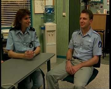
f0            f i−2            f i−1                fi              f i+1         f n−2
created, range images. Given the vast amount of existing                                ...                                                                 ...
                                                                         F0                            Fi−1            Fi                    Fi+1                         Fn−1
2D material, this is an important application.
                                                                        p               ...                                 p                               ...
   The basic idea of our approach is to estimate motion in                  0                                                   i
                                                                                                                                                                          p n−1
the monoscopic video stream and to apply this motion in-                                ...                                                                 ...
                                                                                b1            b i−1           bi                     b i+1          b i+2         b n−1
formation for synthesizing the missing range images. The
technical details are described in next section. Given a color          D0                                             Di                                                 Dn−1

image and its corresponding range image, a stereo pair can              d0                                                  di
be synthesized by a special 3D image warping technique                                                                                                                    d n−1

[3, 10]. Experimental results are reported in Section 3. Fi-
nally, we conclude the paper with some discussion.
                                                                        Figure 1. Depth tracking from motion analy-
2. Synthesizing range images                                            sis

   It is assumed that a monoscopic (color) video stream is           of such untrackable situations, it is necessary that the ob-
given by n frames F0 , . . . , Fn−1 , along with depth informa-      served scene does not change too much, so that roughly the
tion D0 and Dn−1 for the first and the last frame. The goal is       same objects are visible in F0 and Fn−1, albeit at different
to expand the depth information from D0 and Dn−1 so that             positions. If this requirement is not fulfilled, the scene may
a complete set of range images D0 , . . . , Dn−1 is available for    have to be divided into sub-scenes.
the subsequent depth-image-based rendering step.
                                                                     2.2. Details of Depth Tracking
2.1. Range Image Synthesis by Depth
     Tracking                                                            The key part of depth tracking is the per-pixel motion
                                                                     estimation: The more precise it is, the better the depth ap-
    The basic idea is to track each point in the scene as it         proximation. We have experimented with two approaches
moves to different pixel positions from frame to frame. For          to compute motion vector fields: optical flow and block
a point P at position pi ∈ Fi , 0 < i < n − 1, the correspond-       matching.
ing positions p0 ∈ F0 and pn−1 ∈ Fn−1 are then known, and                Optical flow: The per-pixel motion vector fields are in
therefore also the associated depths d0 and dn−1 . The depth         fact dense optical flow fields. Optical flow computation
di required for the unknown depth map Di can then be com-            techniques can be classified into local methods that opti-
puted by an interpolation of d0 and dn−1 .                           mize some local energy-like expression and global strate-
    To be able to compute the position pi+1 ∈ Fi+1 of a point        gies that attempt to minimize a global energy functional.
P with a given position pi ∈ Fi , it is necessary to know the        Examples are the Lucas-Kanade method and the classical
forward motion vector fi (pi ): pi+1 = pi + fi (pi ). Sim-           work of Horn-Schunck, respectively.
ilarly, the position pi−1 in Fi−1 of the point can be com-               Local and global methods have quite different smoothing
puted when the backward motion vector bi (pi ) is known:             effects. Consequently, it is desirable to combine them in or-
pi−1 = pi + bi (pi ). To handle all points of the scene, the         der to design novel approaches of both the high robustness
forward and backward motion vector fields f0 , . . . , fn−2 and      of local methods and the full density of global techniques.
b1 , . . . , bn−1 that contain motion vectors for each pixel posi-   A recent combination scheme is proposed in [2]. This tech-
tion must be computed. Note that it is not enough to know            nique and the methods of Lucas-Kanade and Horn-Schunck
the motion vectors of only one direction, because the per-           are used in our experiments.
pixel motion between two frames is not bijective. The com-               Block matching: Block matching techniques are com-
plete process of depth tracking from motion analysis is il-          monly used in feature tracking applications and in stereo
lustrated in Figure 1. Details will be given in Section 2.2.         correspondence search: to find a match for the pixel at posi-
    Based on the depth tracking the missing range images             tion p in frame F0 at some position q in frame F1 , a block of
are synthesized in the following way. A point P with a given         size (2k + 1) × (2k + 1) around p is examined, and the best
position pi in frame Fi is tracked backwards to some posi-           match for this neighborhood is searched in F1 . If q̂ is the po-
tion p0 in frame F0 and forwards to some position pn−1 in            sition of the match candidate currently under consideration,
frame Fn−1 . We distinguish between three cases: 1) Both             then its matching costs are defined as:
backward and forward tracking are successful: A linear in-
                                                                                                        k          k
terpolation of the corresponding depth values d0 and dn−1 is
performed to determine di ; 2) It can only be tracked to one
                                                                                     C(p, q̂) =       ∑ ∑              c(p + (r, c), q̂ + (r, c))                                (1)
                                                                                                      r=−k c=−k
of both end frames: di is set to the depth value at this end
frame, thus assuming that it remains constant over time; 3)          The candidate position q̂ with the lowest matching costs
It can neither be tracked to F0 nor to Fn−1 : the depth di is        wins. The cost function c differs between various block
arbitrarily set to ”far”. To avoid too frequent occurrences          matching variants.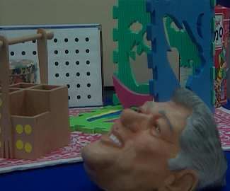
−2 −1   0   +1 +2
                               −2 22 18 12 19 23
                                                                              of their length, so the sum of differences does not need to
                               −1 14     6   4   7   15                       be computed. The distance penalty also reduces the uncer-
                                0   10   2   1   3   11                       tainty, for example in areas with periodic textures, where
                               +1   16   8   5   9   17
                                                                              good matches are found at multiple positions.
                               +2   24 20 13     21 25
                                                                                  Consistency check: A postprocessing step often used for
   Figure 2. Order in which motion vectors are                                stereo correspondence search is adapted to improve the mo-
   tested: Example for 25 vectors at a maximum                                tion vector fields for depth tracking, regardless of the mo-
   distance d = 2                                                             tion estimation method they were created with.
                                                                                  To catch unreliable motion vectors, the motion estima-
                                                                              tion is done in both directions: from F0 to F1 , leading to
   One popular cost function uses the absolute difference of
                                                                              the vector field f , and from F1 to F0 , leading to the vec-
pixel values:
                                                                              tor field b. The reliability of a motion vector v in f will
                cSAD (p, q) = |F0 (p) − F1(q)|                                be high if the corresponding motion vector in b points back
                                                                              to the position of v or near to it. A threshold t determines
This expression can be easily extended to handle color im-                    the maximum allowed difference for vectors to be consid-
ages. The YUV color space is widely used in video process-                    ered reliable. If the difference is greater, the vector v in
ing applications. The Y component represents the bright-                       f is marked as unreliable. In a second step, all unreliable
ness of a point, and the U and V components define its hue                    vectors in f are replaced by interpolating neighboring reli-
and saturation1 . Thus, the following term can be used:                       able vectors. This is done in a way that ensures that vectors
                                                                              with a high number of reliable neighbors are replaced first,
  cSAD (p, q) = L · |Y (F0 (p)) − Y (F1 (q))| + (1 − L) · 12 ·                to avoid propagating errors as much as possible. The result
     (|U(F0 (p)) − U(F1(q))| + |V (F0 (p)) − V (F1 (q))|)                     is an improved vector field f ∗ . By swapping the roles of f
                                                                              and b, the same can be done with b, leading to the improved
Each of the components Y, U, V is expected to be in [0, 1]                    field b∗ . Since the motion estimation for depth tracking has
in this equation. L is the luminance weight: It determines                    to be done in both directions anyway, the consistency check
how much influence luminance differences should have in                       imposes little additional computation costs.
comparison to color differences.
   To increase the computational efficiency and simulta-                      3. Experimental results
neously reduce the uncertainty of the method, the SAD
block matching variant for depth tracking uses the following                  3.1. Test material
matching cost function, which is an extension of Eq. (1):
                                                                                Three example video scenes were used:
     CSAD (p, q̂) = D · distance
                              k
                                (p,q̂)
                                       +                                        • Interview: This scene shows a man and a woman sit-
                    k     k                                            (2)        ting at a table and having a chat. It is roughly ten
      (1 − D) ·    ∑ ∑              cSAD (p + (r, c), q̂ + (r, c))                seconds long (251 frames) and has a resolution of
                  r=−k c=−k                                                       720 × 576 pixels, which corresponds to the European
The additional term is a distance penalty: Larger motion                          PAL TV standard.
vectors cause higher matching costs. The parameter D de-                        • Orbi: In this scene, a camera moves around a table
termines the balance between the distance penalty and the                         with various sorts of toys. Its length is five seconds
sum of absolute pixel value differences. It should be small                       (126 frames), and its resolution is 650 × 540.
(≤ 0.1), because large distance penalties corrupt the results.                   • Nasa: This scene shows an astronaut working on a
   The introduction of a distance penalty for the candidate                        space shuttle, with the earth in the background. It is
position q̂ has a nice side-effect of allowing to shortcut the                     eighteen seconds long (451 frames). The resolution is
computation of CSAD : If motion vectors q̂ − p are tested                          528 × 360.
in the order of ascending length (see Figure 2), then the                     The scenes Interview and Orbi (see Figure 3 for two im-
full costs CSAD do not have to be computed if the distance                    ages of each video) have known depth maps for each video
penalty alone is already greater than the total cost of the                   frame, recorded with a real-time depth sensor. The real
previously tested optimal vector. This is frequently the case                 depth data can be used as ground truth when evaluating
in background areas of scenes: since no object moves, a                       computed depth data.
very good match with CSAD near zero is already found                             The scene Nasa is a part of a NASA mission video2. It is
at a motion vector near (0, 0). Motion vectors tested at a                    a conventional 2D video without any depth data. Three sim-
later time then exceed these very low costs already because
                                                                                2 http://spaceflight.nasa.gov/gallery/video/
  1 Though not in the direct   way as for example the HSL color space does.   shuttle/sts-114/qtime/114_fdh05_clip3.mov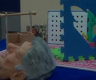
D0                 D25          Diff. D0 and D25

                                                                          D12 from HS                  D12 from LK

   Figure 3. Video Interview and Orbi with real
   depth data

plistic, qualitative range images were created manually with
minimal efforts: one for the first frame, one for the middle
frame, and one for the last frame, resulting in a distance of            D12 from CLG                  D12 from SAD
225 frames between two known depth maps.
                                                                    Figure 4. Interview video: depth maps D12 from
                                                                    depth tracking with different motion estima-
3.2. Evaluation of depth tracking                                   tion methods

    The three optical flow methods and the SAD block
matching method were tested to find the best per-pixel mo-        depth maps can be used as an error measurement:
tion estimation method for depth tracking. In the following                        n−1 N−1 M−1
we report some results of evaluating the depth tracking qual-                      ∑ ∑ ∑ |Di (x, y) − GTi (x, y)|
ity based on the Interview video; see [4] for more details.                        i=0 y=0 x=0
                                                                           EDT =
    The frames F0 , . . . , F250 (ten seconds) of the Inter-                                     nNM
view scene were extracted, along with real depth data             This average depth error value is in [0, 255] (the smaller,
D0 , D25 , . . . , D250 for every 25th frame. The missing depth   the better). Table 1 shows the results for the complete se-
maps were computed using depth tracking with the motion           ries of depth maps from which the examples in Figure 4
estimation method under examination.                              where taken. The depth maps with the lowest errors accord-
    Figure 4 shows two frames D0 and D25 and, for illus-          ing to this measurement are the ones from the SAD block
trating the motion between these two frames, the differ-          matching method. This confirms the first impressions from
ence image. In addition we can see the depth map D12              Figure 4. Similar behavior has been consistently observed
produced with the four motion estimation methods. For             for the videos Interview and Orbi. Currently, we still can-
Horn/Schunck (HS), Lucas/Kanade (LK), and the combined            not make conclusive claims. Other videos may well show
local/global (CLG) method, some errors in motion estima-          another picture, i.e., different video material may require
tion are clearly visible. For example, around the head of the     different motion analysis methods.
man, the effects of linear interpolation outweigh the effects     3.3. Rating of 3D video quality
of motion estimation. The SAD block matching method
seems to deliver the best motion estimation, resulting in the        Several 3D video variants of each of the videos Inter-
most accurate depth map. Around the head of the man, for          view, Orbi, and Nasa were computed from different depth
example, only small effects of linear interpolation are visi-     data, and prepared for display on a 2018XLQ 19” 3D mon-
ble; for the most part, its motion was followed correctly.        itor from DTI3 , which is an autostereoscopic display, al-
    The differences between ground truth and the computed           3 http://www.dti3d.com/
by choosing better parameters for the rendering step, but
HS LK CLG SAD this was not subject of the test. Most viewers noticed the
error EDT 2.32 2.46 2.30 1.74 absence of any 3D effect in the 2D variant. Remarkably,
the 3D videos synthesized by depth tracking was rated sim-
Table 1. Error values for all Interview depth ilar to those from the ground truth depth information with
maps created with the motion estimation respect to both image quality and 3D effect.
methods
4. Conclusions
Image Quality 3D Effect
In this paper we have considered a range image synthe-
10 10
sis technique for reducing the need of full availability of a
8 8
range video stream in DIBR-based 3D video creation. Our
6 6
approach eases the recording of 3D material by using less
4 4 expensive range sensors and enables to enhance existing
2 2 2D video material with 3D effect by limited manual over-
0 0 head. Experiments on three videos have demonstrated very
2D GT DT 2D GT DT
encouraging results. Especially, one 3D video was gener-
Interview Orbi Nasa ated from a 2D video without any sensory 3D data avail-
Figure 5. Rating of image quality and 3D ef- able at all. In all cases the test viewers have attested similar
fect for the variants 2D, Ground Truth, Depth 3D video quality for our synthesis technique and rendering
Tracking based on depth ground truth.
References
lowing 3D viewing experiences without the need of wear-
ing any glasses. Interested readers can find a summary of
[1] S. Battiato et al. 3D Stereoscopic Image Pairs by Depth-
(mostly commercially available) autostereoscopic displays
Map Generation. In Proceedings of 3D Data Processing
at http://www.stereo3d.com/displays.htm. Visualization and Transmission, pages 124–131, 2004.
A group of 10 test viewers was asked to rate both the im- [2] A. Bruhn et al. Lucas/Kanade Meets Horn/Schunck: Com-
age quality and the quality of the 3D effect of each variant, bining Local and Global Optic Flow Methods. International
on a scale from 0 (”very bad” or ”nonexistent”) to 10 (”ex- Journal of Computer Vision, 61(3):211–231, 2005.
cellent”). A note handed out to each test viewer clarified [3] C. Fehn et al. Key Technologies for an Advanced 3D-TV
that image quality means the absence of noise and distortion System. In Proceedings of SPIE Three-Dimensional TV,
in the image, and 3D effect quality means the impression of Video and Display III, pages 66–80, Philadelphia, 2004.
real depth. The viewers did not have any experience with [4] M. Lambers. Synthesis of 3D Videos. Master’s thesis, Uni-
versity of Münster, 2005.
3D videos, and they did not know anything about the nature
[5] K. Moustakas et al. A Non Causal Bayesian Framework for
of the videos and their variants. Object Tracking and Occlusion Handling for the Synthesis
The following three variants were tested: of Stereoscopic Video. In Proceedings of 3D Data Process-
1. 2D: The original 2D video. Presenting this variant ing Visualization and Transmission, pages 147–154, 2004.
allows to measure the impact that depth-image-based [6] D. Nistér. Automatic Passive Recovery of 3D from Images
rendering has on image quality. and Videos. In Proceedings of 3D Data Processing Visual-
ization and Transmission, pages 438–445, 2004.
2. Ground Truth: A 3D video based on real depth maps. [7] M. Pollefey. 3D from Image Sequences: Calibration, Mo-
This variant is expected to show the best results in tion and Shape Recovery. In N. Paragios et al., editor, Hand-
terms of 3D effect quality. For the Nasa scene, this book of Mathematical Models in Computer Vision, pages
option was not used due to the lack of real depth data. 389–403. Springer, 2006.
[8] E. Prados and O. Faugeras. Shape from Shading. In N. Para-
3. Depth Tracking: A 3D video based on depth data that gios et al., editor, Handbook of Mathematical Models in
was computed using the depth tracking method. For Computer Vision, pages 375–388. Springer, 2006.
Interview and Orbi, every 25th depth map from ground [9] A. Redert et al. ATTEST – Advanced Three-Dimensional
truth was used as initial depth data. For Nasa, the three Television System Technologies. In Proceedings of 3D Data
artificial depth maps were used. Processing Visualization and Transmission, pages 313–319,
Padova, Italy, 2002.
The rating results are shown in Figure 5. Comparing the [10] L. Zhang and W. Tam. Stereoscopic Image Generation
rating of the 2D variant with the results of other variants Based on Depth Images for 3D TV. IEEE Transactions on
shows that the image quality always suffers a little from Broadcasting, 51(2):191–199, 2005.
depth-image-based rendering. This effect may be reducibleYou can also read