SYSTEM CART USER MANUAL - ATRICURE
←
→
Page content transcription
If your browser does not render page correctly, please read the page content below
System Cart
User Manual

Chariot du système – Manuel d'utilisation
Systemwagen – Benutzerhandbuch
Sistema carrello – Manuale d'uso
Carrinho do Sistema – Manual do Usuário
Carro del sistema – Manual del usuario
System-vogn - Brugervejledning
Systeemkar – Gebruikershandleiding

 P000880.K
AtriCure System Cart – User’s Manual
 P000880.K
 Table of Contents

 Page
1.0 System Overview............................................................................................. 2
2.0 How to Use this Manual................................................................................... 3
3.0 System Description.......................................................................................... 4
4.0 Proper Use ...................................................................................................... 5
5.0 EMC Guidance and Manufacturer’s Declaration ............................................. 7

CAUTION: Federal (U.S.) law restricts this device to sale by or on the order of a physician.

 Manufactured by: European Representative:
 AtriCure Incorporated AtriCure Europe B.V.
 7555 Innovation Way De entree 260
 Mason, Ohio 45040 USA 1101 EE Amsterdam
 Customer Service: The Netherlands
 1-866-349-2342 (toll free) +31 20 7005560
 1-513-755-4100 (phone) ear@atricure.com

Information in this document is subject to change without notice. Reproduction of this document
in any manner whatsoever without the written permission of AtriCure, Inc. is strictly forbidden.
AtriCure and the AtriCure Logo are trademarks of AtriCure, Inc. AtriCure disclaims proprietary
interest in the marks and names of others.
Printed in the USA.
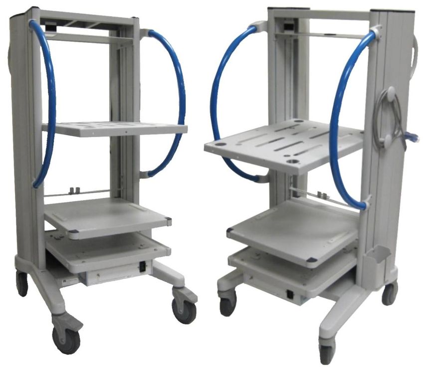
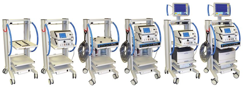
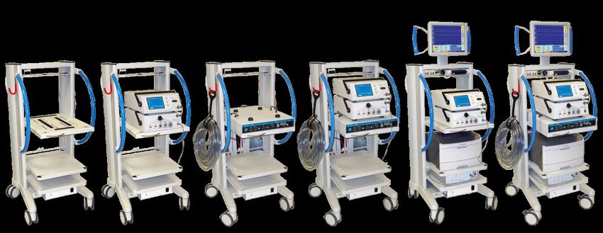
AtriCure, Inc. P000880.K

1. System Overview

1.0 Basic Cart
AtriCure developed a ‘modular’ approach to the cart. The System Cart consists of the Basic Cart
(ASCB2) and two optional upgrade kits: (1) the Cryo Cart Kit (ASCC2); and (2) the ORLab Cart
Kit (ASCO).

 Figure 1: Basic Cart (ASCB2)
1.1 Customer Options
The modular approach allows customization to support all AtriCure components and
accessories.

 Figure 2
 (1) Basic Cart; (2) Basic Cart with ASU and ASB; (3) Basic Cart with cryoICE BOX; (4) Basic Cart, ASU,
 and ASB, Cryo Cart Kit and cryoICE BOX; (5) Basic Cart, ASU and ASB, ORLab Cart Kit and ORLab
 components; and (6) Basic Cart, ASU and ASB, ORLab Cart Kit, ORLab components, Cryo Cart Kit and
 cryoICE BOX.

 2 of 88 2021/04
AtriCure, Inc. P000880.K

2.0 How to Use this Manual
The following information is essential for safe and efficient operation of the AtriCure System
Cart.

2.1 Table of symbols used in this manual

 Item # Symbol Description

 1.
 Consult operating instructions.

 2. Follow local governing ordinances and recycling
 plans regarding disposal or recycling of device
 components.

 3. Manufactured by.

 4. Alternating Current.

 5. CE Mark.

 6.
 Temperature Storage Range

 7. Humidity Storage Range

 8.
 Voltage.

 9.
 Waste Electrical and Electronic Equipment (WEEE)

 10.
 Non-Sterile

 Table 1: Symbols.

 3 of 88 2021/04
AtriCure, Inc. P000880.K

3.0 System Description

The System Cart supports medical equipment used in procedures for the treatment of
arrhythmias in cardiothoracic theatres and hospital electrophysiological laboratories.
The complete system is comprised of five sub-systems:

 1. AtriCure® Ablation Sensing Unit (ASU) produces and delivers RF energy, in a bipolar
 mode, at a frequency of approximately 460 kHz, with a maximum output power ranging
 from 12 Watts up to 30 Watts depending on the operating mode.

 2. AtriCure® Switch Matrix (ASB) is a reusable accessory interface module that allows
 simultaneous connection of AtriCure® Isolator™ Transpolar™ ablative handpiece and
 pen devices to the ASU RF generator.

 3. AtriCure® cryoICE BOX (ACM) is an electro-mechanical and pneumatic cryogenic
 surgical system that delivers a cryogenic energy source, namely Nitrous Oxide, to create
 lines of ablation through cardiac tissue.

 4. AtriCure® ORLab is a programmable diagnostic cardiac stimulator with
 electrocardiogram display tailored for use as a diagnostic tool during surgical and RF
 ablation procedures.

 a. NOTE: Lexmark MS310D printer is used in conjunction with the ORLab to
 produce paper copies of diagnostic read outs.

 b. NOTE: The handpiece and pen devices are separate components and are not a
 part of the AtriCure® Basic Cart.

 5. AtriCure® System Cart is a 450 mm wide cart with an onboard Isolation Transformer.
 The Isolation Transformer supplies power to the other subsystems of AtriCure® System
 Cart.

No part of the AtriCure® System Cart or its accessories is intended to make contact the patient,
instead, pacing stimuli are delivered, and ECG signal recorded, via AtriCure® Handpieces and
approved third party products, which may include transvenous endocardial electrode catheters
or epicardial mapping.

Indications for Use: The AtriCure System Cart is intended to be used as an accessory to the
AtriCure Bipolar System, AtriCure Cryo Module System, and ORLab.

3.1 Equipment Classification
3.1.1 The AtriCure® System Cart consisting of the Basic Cart, the Cryo Cart Kit, and the
ORLab Cart Kit are categorized as: Class 1 Equipment; Type CF Applied Part; IPX0; rated for
115-230 VAC 50-60 Hz; and 1800 VA.

 4 of 88 2021/04
AtriCure, Inc. P000880.K

4.0 Proper Use
4.1 NOTE: The AtriCure® System Cart consists of the Basic Cart and is ONLY intended to for
use for the equipment in Table 2. A Cryo Cart Kit and an ORLab Cart Kit are also available and
are ONLY intended for use with the equipment listed in Table 2.

4.2 NOTE: The cart should never be used to carry equipment other than what is specified in
this manual. The cart should not be operated on an incline exceeding 10°. During operation
and storage, the casters should be locked securely.

4.3 NOTE: This manual does not address specific instructions related to the equipment listed
in Table 2. The user should refer to product specific manuals provided with individual
components and systems for information pertaining to: (1) explanation of the function of controls,
displays, and signals; (2) the sequence of operation; (3) the connection and disconnection of
detachable parts and accessories; (4) indications of recognized accessories, detachable parts,
and consumable materials; and (5) signal output or signal input ports intended only for
connection to specified equipment described.

4.4 NOTE: Unplug cart before transport.

 Manufacturer Equipment Description Product Code
 MicroPace ORLab EP Cardiac Stimulator / Recorder System ORLab
 AtriCure AtriCure Ablation and Sensing Unit ASU2 / ASU3
 AtriCure AtriCure Source Switch Accessory ASB1 / ASB3
 Lexmark Laser Printer MS310D
 AtriCure cryoICE BOX ACM1 / ACM2
 Table 2: Compatible Equipment List.

4.5 Cleaning Instructions
4.5.1 NOTE: The Basic Cart Cleaning and Disinfection Instructions: (1) use a mild detergent
(prepared to its specifications) and a damp cloth; and (2) do not use caustic, corrosive, or
abrasive cleaning materials.

4.6 Serviceable Parts
4.6.1 NOTE: The System Cart consisting of: the Basic Cart; the Cryo Cart Kit; and ORLab Cart
Kit does not have any serviceable parts. For servicing issues, contact AtriCure, Inc.

4.7 Environmental
4.7.1 NOTE: Environmental Conditions: (1) operational temperature +10° C to +40° C; (2)
storage temperature -35° C to +54° C; and (3) humidity 15% to 90% relative humidity.

 5 of 88 2021/04
AtriCure, Inc. P000880.K

4.8 Preventative Maintenance
4.8.1 NOTE: Perform annual preventative maintenance procedures to ensure all Cart
components are functioning properly, including but not limited to: (1) electrical power cords for
fraying, damage, and proper grounding; (2) AC power switch; and (3) caster damage.

4.9 Safety Information
4.9.1 PRECAUTION: To avoid electrical hazards, all parts of the ORLab, including the
computer, monitor, Stimulus Generator Unit, and Lexmark laser printer must be connected to the
Isolation Transformer and never directly to a mains outlet.

4.9.2 PRECAUTION: To avoid risk of electric shock, the Isolation Transformer must only be
connected to a supply mains with protective earth.

4.9.3 PRECAUTION: To avoid electrical hazards and prevent overloading the transformer, do
not connect any non-AtriCure approved equipment to the supplied Mains Isolation Transformer.

4.9.4 PRECAUTION: Use AtriCure® System Cart only in ventilated areas and away from
flammable gasses. To avoid risk of explosion, the Basic Cart should only be used in a ventilated
area as gasses may be released during charging of backup battery, and should not be used in
rooms with flammable anaesthesia.

4.9.5 PRECAUTION: AtriCure® System Cart is not suitable for use in the presence of a
flammable anaesthetic mixture with air or with oxygen or nitrous.

4.9.6 PRECAUTION: Secure tank with chain and ONLY use N2O Tanks ≤ 20 cm (8") in
diameter that weigh ≤ 29.5 kg (65 pounds). Due to the weight of the N2O tanks, use caution
while lifting and securing the tanks.

4.9.7 PRECAUTION: If the cryoICE Box is connected to a grounded hospital AC power
receptacle, it must be connected into the same grounded hospital AC power receptacle as
Isolation Transformer.

4.9.8 PRECAUTION: When the Isolation Transformer is plugged into the mains outlet, leave at
least 2 ft clearance between the back of the AtriCure® System Cart and the wall to allow access
for disconnection.

4.9.9 PRECAUTION: AtriCure® System Cart atmospheric storage condition is 68.6 kPa to
101.3 kPa and the operating condition is 69.1 kPa to 101.3 kPa

4.9.10 PRECAUTION: No modification of this equipment is allowed.

 6 of 88 2021/04
AtriCure, Inc. P000880.K

5.0 EMC Guidance and Manufacturer’s Declaration
5.1 Electromagnetic Emissions
 The AtriCure System Cart (ASC2), along with its associated equipment (ASU2 / ASU3,
 ASB3, ACM1 / ACM2, and ORLab), from here on referred to as the AtriCure RF, Cryo,
 and EP Mapping System (ARC-EPMS) have been tested and found to comply with the
 limits for medical devices in IEC 60601-1-2:2014. These limits are designed to provide
 reasonable protection against harmful interference in a typical medical installation.
 The ARC-EPMS can radiate radio frequency energy and, if not installed and used in
 accordance with the instructions, may cause harmful interference to other devices in the
 vicinity. However, there is no guarantee that interference will not occur in a particular
 installation.

 Guidance and manufacturer’s declaration – electromagnetic emissions
 The AtriCure RF, Cryo, and EP Mapping System (ARC-EPMS) is intended for use in the electromagnetic
 environment specified below. The customer or the user of the ARC-EPMS unit should ensure that it is
 used in such an environment.
 Emissions test Compliance Electromagnetic environment – guidance
 The ARC-EPMS unit, with the exception of the ASU2 /
 ASU3 RF Generator only during RF energy delivery,
 uses RF energy only for its internal function.
 RF emissions CISPR 11 Group 1
 Therefore, its RF emissions are very low and are not
 likely to cause any interference in nearby electronic
 equipment.
 RF emissions
 CISPR 11 Class A The ARC-EPMS unit is suitable for use in all
 establishments other than domestic and those directly
 connected to the public low-voltage power supply
 Harmonic emissions
 Class A network that supplies buildings used for domestic
 IEC 61000-3-2
 purposes.
 Voltage fluctuations/
 flicker emissions
 Complies
 IEC 61000-3-3

 7 of 88 2021/04
AtriCure, Inc. P000880.K

 5.1.1 Electromagnetic Immunity
 Guidance and manufacturer’s declaration – electromagnetic immunity
 The AtriCure RF, Cryo, and EP Mapping System (ARC-EPMS) is intended for use in the electromagnetic
 environment specified below. The customer or the user of the ARC-EPMS unit should ensure that it is
 used in such an environment.
 Electromagnetic environment –
 Immunity test IEC 60601 test level Compliance level
 guidance
 ± 8 kV contact ± 8 kV contact Floors should be wood, concrete,
 Electrostatic
 ± 2 kV, ± 4 kV, ± 8 kV, ± 2 kV, ± 4 kV, ± 8 kV, or ceramic tile. If floors are
 discharge
 ± 15 kV air ± 15 kV air covered with synthetic material,
 (ESD) IEC
 the relative humidity should be at
 61000-4-2
 least 30 %.
 Electrical fast ± 2 kV @ 100 kHz ± 2 kV @ 100 kHz Mains power quality should be
 transient/burst repetition frequency for repetition frequency for that of a typical commercial or
 IEC 61000-4-4 power supply lines power supply lines hospital environment.
 ± 2 kV @ 100 kHz ± 2 kV @ 100 kHz
 repetition frequency for repetition frequency for
 input/output lines input/output lines
 Mains power quality should be
 Power inputs Power inputs that of a typical commercial or
 ± 0,5 kV, ± 1 kV Line- ± 0,5 kV, ± 1 kV Line-to- hospital environment.
 to-Line Line
 Surge
 IEC 61000-4-5 ± 0,5 kV, ± 1 kV, ± 2 ± 0,5 kV, ± 1 kV, ± 2 kV
 kV Line-to-Ground Line-to-Ground
 Signal input/outputs: Signal input/outputs:
 ± 2 kV Line-to-Ground ± 2 kV Line-to-Ground
 0,15 MHz – 80 MHz 0,15 MHz – 80 MHz
 3V, 80 % AM at 1 kHz 3V, 80 % AM at 1 kHz
 Mains power quality should be
 Conducted RF ISM bands between ISM bands between that of a typical commercial or
 IEC 61000-4-6 0,15 MHz and 80 MHz 0,15 MHz and 80 MHz hospital environment.
 6V, 80 % AM at 1 kHz 6V, 80 % AM at 1 kHz
 Voltage dips, Mains power quality should be
 short Voltage Dips: Voltage Dips: that of a typical commercial or
 interruptions 0 % UT; 0,5 cycle 0 % UT; 0,5 cycle hospital environment. If the user of
 and voltage the ARC-EPMS unit requires
 variations on At 0°, 45°, 90°, 135°, At 0°, 45°, 90°, 135°, continued operation during power
 power supply 180°, 225°, 270° and 180°, 225°, 270° and mains interruptions, it is
 input lines 315° phase angles 315° phase angles recommended that the
 IEC 61000-4-11 0 % UT; 1 cycle and 0 % UT; 1 cycle ARC-EPMS unit be powered from
 an uninterruptible power supply or
 70 % UT; 25/30 cycles Single phase: at 0° a battery.
 Single phase: at 0° 70 % UT; 25/30 cycles
 Voltage interruptions: Single phase: at 0°
 0 % UT; 250/300 cycle Voltage interruptions:
 0 % UT; 250/300 cycle
 Power Power frequency magnetic fields
 frequency should be at levels characteristic
 30 A/m 30 A/m
 (50/60 Hz) of a typical location in a typical
 magnetic field 50 Hz or 60 Hz 50 Hz or 60 Hz commercial or hospital
 IEC 61000-4-8 environment.
 NOTE: UT is the a.c. mains voltage prior to application of the test level.

 8 of 88 2021/04
AtriCure, Inc. P000880.K

 5.1.2 EMC Guidance and Manufacturer’s Declaration
 Immunity Test Level Compliance Test
 Immunity test Band (MHz) Wireless Service
 (V/m) Level (V/m)
 150 kHz to 80 MHz General
AtriCure, Inc. P000880.K

 5.1.3 Recommended Separation Distance
 Recommended separation distances between portable and mobile RF communications
 equipment and the AtriCure RF, Cryo, and EP Mapping System
 The AtriCure RF, Cryo, and EP Mapping System (ARC-EPMS) is intended for use in an electromagnetic
 environment in which radiated RF disturbances are controlled. The customer or the user of the ARC-EPMS
 can help prevent electromagnetic interference by maintaining a minimum distance between portable and
 mobile RF communications equipment (transmitters) and the ARC-EPMS as recommended below,
 according to the maximum output power of the communications equipment.

 Separation distance according to frequency of transmitter m
 Rated maximum
 output power of
 transmitter W 150 kHz to 80 MHz 80 MHz to 800 MHz 800 MHz to 2.5 GHz
 d = 1.2 √P d = 1.2 √P d = 2.3 √P

 0.01 0.12 0.12 0.23
 0.1 0.38 0.38 0.73
 1 1.2 1.2 2.3
 10 3.8 3.8 7.3
 100 12 12 23
 For transmitters rated at a maximum output power not listed above, the recommended separation distance
 d in meters (m) can be estimated using the equation applicable to the frequency of the transmitter, where
 P is the maximum output power rating of the transmitter in watts (W) according to the transmitter
 manufacturer.

 NOTE 1: At 80 MHz and 800 MHz, the separation distance for the higher frequency range applies.

 NOTE 2: These guidelines may not apply in all situations. Electromagnetic propagation is affected by
 absorption and reflection from structures, objects, and people.

5.1.4 Responsibility of the Manufacturer

 AtriCure is responsible for safety, reliability, and performance of the equipment only
 if:
 • Installation procedures in this manual are followed.
 • Persons authorized by AtriCure carry out modifications or repairs.
 • The electrical installation of the relevant room complies with local codes and
 regulatory requirements such as IEC and BSI.
 • The equipment is used in accordance with the AtriCure User’s Manual.

 DISCLAIMER
Under no circumstances will AtriCure, Inc. be responsible for any incidental, special or
consequential loss, damage, or expense, which is the result of the deliberate misuse of this
product, including any loss, damage, or expense which is related to personal injury or damage to
property.

 10 of 88 2021/04
AtriCure, Inc. P000880.K

 Chariot du système AtriCure — Manuel d’utilisation
 P000880.K
 Table des matières

 Page
1.0 Présentation du système ............................................................................... 12
2.0 Comment utiliser ce manuel .......................................................................... 13
3.0 Description du système ................................................................................. 14
4.0 Utilisation conforme ....................................................................................... 15
5.0 Directives de compatibilité électromagnétique et déclaration du fabricant .... 18

MISE EN GARDE : Conformément à la législation américaine, cet appareil ne peut être vendu
que par un médecin ou sur prescription médicale.

 Fabriqué par : Représentant européen :
 AtriCure Incorporated AtriCure Europe B.V.
 7555 Innovation Way De entree 260
 Mason, Ohio 45040 États-Unis 1101 EE Amsterdam
 Service clients : The Netherlands
 1-866-349-2342 (numéro gratuit) +31 20 7005560
 1-513-755-4100 (téléphone) ear@atricure.com

Les informations contenues dans ce document sont sujettes à modification sans préavis. La
reproduction de ce document de quelque manière que ce soit, sans l’autorisation écrite
d’AtriCure, Inc. est strictement interdite. AtriCure et le logo AtriCure sont des marques
commerciales d’AtriCure, Inc. AtriCure décline tout droit de propriété dans les marques et noms
de tiers.
Imprimé aux États-Unis.

 11 of 88 2021/04
AtriCure, Inc. P000880.K

1. Présentation du système

1.0 Chariot de base
AtriCure a développé une approche « modulaire » du chariot. Le chariot du système se
compose du chariot de base (ASCB2) et de deux kits optionnels de mise à niveau : (1) le kit de
chariot Cryo (ASCC2) et (2) le kit de chariot ORLab (ASCO).

 Figure 1 : Chariot de base (ASCB2)
1.1 Options client
L’approche modulaire permet la personnalisation pour la prise en charge de tous les
composants et accessoires AtriCure.

 Figure 2
 (1) Chariot de base ; (2) Chariot de base avec ASU et ASB ; (3) Chariot de base avec cryoICE BOX ;
(4) Chariot de base, ASU et ASB, Kit de chariot Cryo et cryoICE BOX ; (5) Chariot de base, ASU et ASB,
 Kit de chariot ORLab et composants ORLab et (6) Chariot de base, ASU et ASB, Kit de chariot ORLab,
 composants ORLab et cryoICE BOX.

 12 of 88 2021/04
AtriCure, Inc. P000880.K

2.0 Comment utiliser ce manuel
Les informations suivantes sont essentielles pour un fonctionnement sûr et efficace du chariot
du système AtriCure.

2.1 Tableau des symboles utilisés dans ce manuel

 Élément n° Symbole Description

 1.
 Consulter les instructions d’utilisation.

 2. Respecter les règlementations locales et les
 programmes de recyclage concernant la mise au
 rebut ou le recyclage des composants du dispositif.

 3. Fabriqué par.

 4. Courant alternatif.

 5. Marquage CE.

 6. Plage de température de stockage.

 7.
 Plage d’humidité de stockage.

 8. Tension.

 9. Déchets d’équipements électriques et
 électroniques (DEEE)

 10.
 Non stérile

 Tableau 1 : Symboles.

 13 of 88 2021/04
AtriCure, Inc. P000880.K

3.0 Description du système

Le chariot du système prend en charge les équipements médicaux utilisés dans le cadre du
traitement des arythmies, en salle d’opération cardio-vasculaire et thoracique ainsi que dans les
laboratoires hospitaliers d’électrophysiologie.
Le système complet se compose de cinq sous-systèmes :

 1. L’unité de détection et d’ablation (ASU) AtriCure® produit et délivre une énergie RF,
 en mode bipolaire, à une fréquence d’environ 460 kHz, avec une puissance de sortie
 maximale allant de 12 Watts à 30 Watts selon le mode de fonctionnement.

 2. La matrice de commutation de source (ASB) AtriCure® est un module d’interface
 réutilisable qui permet la connexion simultanée de dispositifs tels que pièces à main et
 stylets d’ablation AtriCure® Isolator™ Transpolar™ au générateur RF de l’ASU.

 3. AtriCure® cryoICE BOX (ACM) est un système de cryochirurgie électromécanique et
 pneumatique qui fournit une source d’énergie cryogénique, en l’occurrence de l’oxyde de
 diazote, pour créer des lignes d’ablation dans un tissu cardiaque.

 4. AtriCure® ORLab est un stimulateur cardiaque programmable de diagnostic, avec
 affichage d’électrocardiogramme personnalisé, destiné à être utilisé comme outil de
 diagnostic lors de procédures d’ablation chirurgicale et RF.

 a. REMARQUE : L’imprimante Lexmark MS310D est utilisée conjointement avec
 l’ORLab pour fournir des copies papier des diagnostics.

 b. REMARQUE : Les pièces à main et les stylets sont des éléments distincts non
 inclus dans le chariot de base AtriCure®.

 5. Le chariot du système AtriCure® est un chariot de 450 mm de large doté d’un
 transformateur d’isolation embarqué. Le transformateur d’isolation alimente les autres
 sous-systèmes du chariot du système AtriCure®.

Aucune partie du chariot du système AtriCure® ou de ses accessoires ne doit entrer en contact
avec le patient ; à la place, les pièces à main AtriCure® et les produits tiers homologués, qui
peuvent inclure des cathéters à électrodes endocavitaires (transveineuses) ou une cartographie
épicardique, appliquent la stimulation et enregistrent le signal ECG.

Consignes d’utilisation : Le chariot du système AtriCure est destiné à être utilisé comme
accessoire du système bipolaire AtriCure, du système de module AtriCure Cryo et d’ORLab.

3.1 Classification de l’équipement
3.1.1 Le chariot du système AtriCure® constitué du chariot de base, du kit de chariot Cryo et
du kit de chariot ORLab est classé comme : équipement de Classe 1 ; pièce appliquée de type
CF ; IPX0 ; prévu pour 115–230 VAC, 50-60 Hz et 1 800 VA.

 14 of 88 2021/04
AtriCure, Inc. P000880.K

4.0 Utilisation conforme
4.1 REMARQUE : Le chariot du système AtriCure® se compose du chariot de base ; il est
destiné UNIQUEMENT à être utilisé avec les équipements mentionnés dans le Tableau 2. Un
kit de chariot Cryo et un kit de chariot ORLab sont également disponibles ; ils sont
UNIQUEMENT destinés à être utilisés avec les équipements mentionnés dans le Tableau 2.

4.2 REMARQUE : Le chariot ne doit jamais être utilisé pour transporter du matériel autre que
celui spécifié dans ce manuel. Le chariot ne doit pas être utilisé sur une pente supérieure à 10°.
Pendant le fonctionnement et le stockage, les roulettes doivent être verrouillées de manière
sûre.

4.3 REMARQUE : Le présent manuel n’aborde pas les instructions spécifiques relatives aux
équipements mentionnés dans le tableau 2. L’utilisateur doit se référer aux manuels spécifiques
relatifs aux produits fournis avec les différents composants et systèmes pour plus d’informations
concernant : (1) l’explication du fonctionnement des commandes, affichages et signaux ; (2) la
séquence d’opérations ; (3) la connexion et la déconnexion de pièces et d’accessoires
amovibles ; (4) les indications relatives aux accessoires homologués, aux pièces amovibles et
aux consommables ; (5) les ports d’entrée ou de sortie des signaux, destinés uniquement à la
connexion des équipements spécifiés décrits.

4.4 REMARQUE : Débranchez le chariot avant transport.

 Fabricant Description de l’équipement Code du produit
 MicroPace Système de Stimulateur cardiaque EP/Enregistreur ORLab
 ORLab
 AtriCure Unité de détection et d’ablation (ASU) AtriCure ASU2/ASU3
 AtriCure Accessoire de commutation de source AtriCure ASB1/ASB3
 Lexmark Imprimante laser MS310D
 AtriCure cryoICE BOX ACM1/ACM2
 Tableau 2: Liste d’équipements compatibles.

4.5 Instructions de nettoyage
4.5.1 REMARQUE : Instructions de nettoyage et de désinfection du chariot de base :
(1) utilisez un détergent doux (préparé conformément à ses spécifications) et un chiffon humide
pour nettoyer le chariot et (2) n’utilisez pas de produits de nettoyage caustiques, corrosifs ou
abrasifs.

4.6 Pièces réparables
4.6.1 REMARQUE : Le chariot du système qui comprend le chariot de base ; le kit de chariot
Cryo et le kit de chariot ORLab ne contient aucune pièce réparable. Pour toute question relative
à une réparation, contactez AtriCure, Inc.

 15 of 88 2021/04
AtriCure, Inc. P000880.K

4.7 Spécifications environnementales
4.7.1 REMARQUE : Conditions environnementales : (1) température de fonctionnement de
+10 °C à +40 °C ; (2) température de stockage de -35 °C à +54 °C et (3) humidité relative de
15 % à 90 %.

4.8 Maintenance préventive
4.8.1 REMARQUE : Effectuez les procédures de maintenance préventive annuelles pour vous
assurer que tous les composants du chariot fonctionnent correctement, y compris mais sans s’y
limiter : (1) les cordons d’alimentation électrique pour s’assurer qu’ils ne sont pas effilochés ou
endommagés et qu’ils sont correctement raccordés à la terre ; (2) l’interrupteur d’alimentation
secteur et (3) les roulettes pour s’assurer qu’elles ne sont pas endommagées.

4.9 Informations relatives à la sécurité
4.9.1 PRÉCAUTION : pour éviter les risques électriques, toutes les parties de l’ORLab, y
compris l’ordinateur, le moniteur, le générateur de stimulations et l’imprimante laser Lexmark
doivent être raccordées au transformateur d’isolation et jamais directement à une prise secteur.

4.9.2 PRÉCAUTION : pour éviter tout risque de choc électrique, le transformateur d’isolation
doit être raccordé uniquement à un réseau d’alimentation doté d’une mise à la terre de
protection.

4.9.3 PRÉCAUTION : pour éviter les risques électriques et les surcharges du transformateur,
vous ne devez jamais connecter un équipement non homologué par AtriCure sur le
transformateur d’isolation secteur fourni.

4.9.4 PRÉCAUTION : utilisez le chariot du système AtriCure® uniquement dans des zones
bien ventilées et à distance de gaz inflammables. Pour éviter tout risque d’explosion, le chariot
de base doit être utilisé uniquement dans un endroit ventilé, car des gaz peuvent être libérés
pendant la charge de la batterie de secours ; il ne doit donc pas être utilisé dans des pièces
contenant des produits anesthésiants inflammables.

4.9.5 PRÉCAUTION : le chariot du système AtriCure® n’est pas prévu pour être utilisé en
présence d’un mélange anesthésiant inflammable avec l’air, l’oxygène ou l’azote.

4.9.6 PRÉCAUTION : fixez solidement le réservoir avec la chaîne et utilisez UNIQUEMENT
des réservoirs de N2O avec un diamètre ≤ 20 cm (8") et un poids ≤ 29,5 kg (65 pounds). En
raison du poids des réservoirs de N2O, prenez vos précautions lorsque vous les soulevez et que
vous les sécurisez.

4.9.7 PRÉCAUTION : si le cryoICE Box est connecté à une prise de courant secteur avec
mise à la terre dans un hôpital, alors il doit être connecté à la même prise de courant secteur
avec mise à la terre que le transformateur d’isolation.

4.9.8 PRÉCAUTION : lorsque le transformateur d’isolation est branché sur la prise de courant
secteur, laissez un espace libre d’au moins 60 cm (2 pieds) entre l’arrière du chariot du système
AtriCure® et le mur pour permettre la déconnexion.

 16 of 88 2021/04
AtriCure, Inc. P000880.K

4.9.9 PRÉCAUTION : les conditions de stockage atmosphérique du chariot du système
AtriCure® sont de 68,6 kPa à 101,3 kPa et les conditions opératoires sont de 69,1 kPa à
101,3 kPa.

4.9.10 PRÉCAUTION : aucune modification de cet équipement n’est autorisée.

 17 of 88 2021/04
AtriCure, Inc. P000880.K

5.0 Directives de compatibilité électromagnétique et déclaration du
 fabricant

5.1 Émissions électromagnétiques
 Le chariot du système AtriCure (ASC2) ainsi que ses équipements associés
 (ASU2/ASU3, ASB3, ACM1/ACM2 et ORLab), désignés par la suite par RF AtriCure,
 Cryo et système de mappage EP (ARC-EPMS), ont été testés et déclarés conformes aux
 limites des appareils médicaux selon la norme CEI 60601-1-2:2014. Ces limites sont
 conçues pour fournir une protection raisonnable contre les interférences nuisibles dans
 une installation médicale type.
 L’ARC-EPMS peut émettre de l’énergie radiofréquence et, s’il n’est pas installé et
 utilisé conformément aux instructions, peut générer des interférences néfastes pour
 les autres dispositifs situés à proximité. Cependant, il n’existe aucune garantie que ces
 interférences ne se produiront pas dans une installation particulière.

 Directives et déclaration du fabricant – émissions électromagnétiques
 RF AtriCure, Cryo et le système de mappage EP (ARC-EPMS) sont conçus pour une utilisation dans
 l’environnement électromagnétique spécifié ci-dessous. Le client ou l’utilisateur de l’ARC-EPMS doit
 s’assurer que l’appareil est bien utilisé dans un tel environnement.
 Test en émission Conformité Environnement électromagnétique — directives
 L’unité ARC-EPMS, à l’exception du générateur
 ASU2/ASU3 RF et uniquement lors de la fourniture
 d’énergie RF, utilise l’énergie RF uniquement pour
 Émissions RF selon
 Groupe 1 son fonctionnement interne. Ainsi, ses émissions RF
 CISPR 11
 sont très faibles et sont peu susceptibles de
 provoquer des interférences dans le matériel
 électronique avoisinant.
 Émissions RF
 CISPR 11 Classe A L’ARC-EPMS peut être utilisé dans tous les
 établissements autres que ceux à usage d’habitation
 et ceux directement connectés au réseau
 Émissions d’harmoniques
 Classe A d’alimentation électrique basse tension qui alimente
 CEI 61000-3-2
 les bâtiments à usage d’habitation.
 Fluctuations de
 tension/scintillement
 Conforme
 (flicker)
 CEI 61000-3-3

 18 of 88 2021/04
AtriCure, Inc. P000880.K

 5.1.1 Immunité électromagnétique
 Directives et déclaration du fabricant — immunité électromagnétique
 RF AtriCure, Cryo et le système de mappage EP (ARC-EPMS) sont conçus pour une utilisation dans
 l’environnement électromagnétique spécifié ci-dessous. Le client ou l’utilisateur de l’ARC-EPMS doit
 s’assurer que l’appareil est bien utilisé dans un tel environnement.
 Environnement
 Niveau de test Niveau de
 Test d’immunité électromagnétique —
 CEI 60601 conformité
 directives
 ±8 kV au contact ±8 kV au contact Les sols doivent être en bois,
 ±2 kV, ±4 kV, ±8 kV, ±2 kV, ±4 kV, ±8 kV, en béton ou en céramique. S’ils
 Décharge
 sont recouverts d’un matériau
 électrostatique (DES) ±15 kV dans l’air ±15 kV dans l’air
 synthétique, alors l’humidité
 CEI 61000-4-2
 relative doit être de 30 % au
 moins.
 ±2 kV @ à la ±2 kV @ à la La qualité de l’alimentation
 fréquence de fréquence de secteur doit être celle d’un
 répétition de 100 kHz répétition de 100 kHz environnement commercial ou
 Transitoires pour les lignes pour les lignes hospitalier typique.
 électriques rapides d’alimentation d’alimentation
 en salves (TERS) ±2 kV @ à la ±2 kV @ à la
 CEI 61000-4-4 fréquence de fréquence de
 répétition de 100 kHz répétition de 100 kHz
 pour les lignes pour les lignes
 d’entrée/sortie d’entrée/sortie
 La qualité de l’alimentation
 Lignes d’entrée Lignes d’entrée secteur doit être celle d’un
 d’alimentation d’alimentation environnement commercial ou
 électrique électrique hospitalier typique.
 ±0,5 kV, ±1 kV en ±0,5 kV, ±1 kV en
 mode différentiel mode différentiel
 Ondes de choc ±0,5 kV, ±1 kV, ±0,5 kV, ±1 kV, ±2 kV
 CEI 61000-4-5 ±2 kV en mode en mode commun
 commun
 Lignes d’entrée/sortie
 Lignes d’entrée/sortie de signaux :
 de signaux :
 ±2 kV en mode
 ±2 kV en mode commun
 commun
 0,15 MHz à 80 MHz 0,15 MHz à 80 MHz La qualité de l’alimentation
 3 V, avec modulation 3 V, avec modulation secteur doit être celle d’un
 d’amplitude de 80 % d’amplitude de 80 % à environnement commercial ou
 à 1 kHz 1 kHz hospitalier typique.
 Perturbations RF
 conduites Bandes ISM entre Bandes ISM entre
 CEI 61000-4-6 0,15 MHz et 80 MHz 0,15 MHz et 80 MHz
 6 V, avec modulation 6 V, avec modulation
 d’amplitude de 80 % d’amplitude de 80 % à
 à 1 kHz 1 kHz

 19 of 88 2021/04
AtriCure, Inc. P000880.K

 Creux de tension, La qualité de l’alimentation
 coupures brèves et Creux de tension : Creux de tension : secteur doit être celle d’un
 variations de tension 0 % UT ; pendant 0 % UT ; pendant environnement commercial ou
 sur les lignes 0,5 cycle 0,5 cycle hospitalier typique. Si
 d’entrée l’utilisateur de l’unité ARC-
 d’alimentation Aux déphasages Aux déphasages EPMS a besoin d’un
 électrique suivants : 0°, 45°, suivants : 0°, 45°, 90°, fonctionnement continu pendant
 CEI 61000-4-11 90°, 135°, 180°, 135°, 180°, 225°, les coupures de courant, il est
 225°, 270° et 315° 270° et 315° recommandé d’alimenter
 0 % UT, pendant 0 % UT, pendant l’unité ARC-EPMS avec une
 1 cycle et 1 cycle alimentation sans interruption
 ou une batterie.
 70 % UT, pendant Monophasé : à 0°
 25/30 cycles
 70 % UT, pendant
 Monophasé : à 0° 25/30 cycles
 Coupures de Monophasé : à 0°
 tension :
 Coupures de tension :
 0 % UT, pendant
 250/300 cycles 0 % UT, pendant
 250/300 cycles
 Champ magnétique à Les champs magnétiques à la
 la fréquence fréquence du secteur doivent
 d’alimentation être à des niveaux
 30 A/m 30 A/m
 (50/60 Hz) caractéristiques d’un lieu
 CEI 61000-4-8 50 Hz ou 60 Hz 50 Hz ou 60 Hz représentatif situé dans un
 environnement commercial ou
 hospitalier type.
 REMARQUE : UT est la tension du courant alternatif secteur avant l’application du niveau de test.

 20 of 88 2021/04
AtriCure, Inc. P000880.K

 5.1.2 Directives de compatibilité électromagnétique et déclaration du fabricant
 Niveau de
 Niveau du test
 Test d’immunité Bande (MHz) Service sans fil conformité du
 d’immunité (V/m)
 test (V/m)
 150 kHz à 80 MHz Généralités
AtriCure, Inc. P000880.K

 5.1.3 Distance de sécurité recommandée
 Distances de séparation recommandées entre les appareils de communication RF
 portables et mobiles et RF AtriCure, Cryo et le système de mappage EP
 RF AtriCure, Cryo et le système de mappage EP (ARC-EPMS) sont conçus pour être utilisés dans un
 environnement électromagnétique dans lequel les perturbations RF rayonnées sont contrôlées. Pour éviter
 toute interférence électromagnétique, le client ou l’utilisateur de l’ARC-EPMS peut maintenir une distance
 minimale entre le matériel de communication RF portable et mobile (émetteurs) et l’ARC-EPMS (voir
 recommandations ci-dessous) en fonction de la puissance de sortie maximale des appareils de
 communication.

 Puissance de Distance de séparation en fonction de la fréquence de l’émetteur (m)
 sortie nominale
 maximale de 150 kHz à 80 MHz 80 MHz à 800 MHz 800 MHz à 2,5 GHz
 l’émetteur (W) d = 1,2 √P d = 1,2 √P d = 2,3 √P

 0,01 0,12 0,12 0,23
 0,1 0,38 0,38 0,73
 1 1,2 1,2 2,3
 10 3,8 3,8 7,3
 100 12 12 23
 Pour les émetteurs ayant une puissance de sortie maximale non répertoriée ci-dessus, la distance de
 sécurité recommandée « d » en mètres (m) peut être déterminée à l’aide de l’équation applicable à la
 fréquence de l’émetteur, où « P » est la valeur de sortie maximale de l’émetteur en watts (W) donnée par
 le fabricant.

 REMARQUE 1 : à 80 MHz et 800 MHz, c’est la distance de séparation de la gamme de fréquences la
 plus élevée qui s’applique.

 REMARQUE 2 : ces directives ne s’appliquent pas nécessairement à toutes les situations. La
 propagation électromagnétique est affectée par l’absorption et la réflexion des
 structures, des objets et des personnes.

5.1.4 Responsabilité du fabricant

 AtriCure est responsable de la sécurité, de la fiabilité et de la performance de
 l’équipement seulement si :
 • Les procédures d’installation de ce manuel sont respectées.
 • Les modifications ou réparations sont effectuées par des personnes agréées par
 AtriCure.
 • L’installation électrique de la pièce concernée est conforme aux normes locales et
 aux exigences réglementaires (CEI et BSI).
 • L’équipement est utilisé conformément au manuel d’utilisation AtriCure.

 AVIS DE NON-RESPONSABILITÉ
AtriCure, Inc. ne sera en aucun cas responsable de toute perte, dommage ou dépense fortuits,
spéciaux ou consécutifs, résultant d’une mauvaise utilisation délibérée de ce produit, y compris
toute perte, dommage ou dépense liés à des blessures corporelles ou à des dommages
matériels.

 22 of 88 2021/04
AtriCure, Inc. P000880.K

 AtriCure Systemwagen – Benutzerhandbuch
 P000880.K
 Inhaltsverzeichnis

 Seite
1.0 Systemübersicht ............................................................................................ 24
2.0 Verwendung dieses Handbuchs .................................................................... 25
3.0 Systembeschreibung ..................................................................................... 26
4.0 Korrekte Verwendung .................................................................................... 27
5.0 EMV-Richtlinie und Herstellererklärung ......................................................... 30

VORSICHT: Laut Bundesgesetz der USA darf dieses Gerät nur durch einen Arzt verkauft oder
verschrieben werden.

 Hergestellt von: Europäischer Bevollmächtigter:
 AtriCure Incorporated AtriCure Europe B.V.
 7555 Innovation Way De entree 260
 Mason, Ohio 45040 USA 1101 EE Amsterdam
 Kundendienst: The Netherlands
 1-866-349-2342 (gebührenfrei) +31 20 7005560
 1-513-755-4100 (Telefon) ear@atricure.com

Die Informationen in diesem Dokument können ohne Vorankündigung geändert werden. Die
Vervielfältigung dieses Dokuments auf beliebige Weise ist ohne schriftliche Genehmigung von
AtriCure, Inc. streng verboten. AtriCure und das AtriCure-Logo sind Handelsmarken von
AtriCure, Inc. AtriCure lehnt jegliches Eigentumsinteresse an den Marken und Namen anderer
ab.
Gedruckt in den USA.

 23 of 88 2021/04
AtriCure, Inc. P000880.K

1. Systemübersicht

1.0 Einfacher Wagen
AtriCure hat einen „modularen“ Ansatz für den Wagen entwickelt. Der Systemwagen besteht aus
dem einfachen Wagen (ASCB2) und zwei optionalen Erweiterungen: (1) dem Cryo-Wagensatz
(ASCC2); und (2) dem ORLab-Wagensatz (ASCO).

 Abbildung 1: Einfacher Wagen (ASCB2)
1.1 Kundenoptionen
Der modulare Ansatz erlaubt die individuelle Anpassung, um alle AtriCure-Komponenten und
Zubehörteile zu unterstützen.

 Abbildung 2
 (1) Einfacher Wagen; (2) Einfacher Wagen mit ASU und ASB; (3) Einfacher Wagen mit cryoICE BOX;
(4) Einfacher Wagen, ASU und ASB, Cryo-Wagensatz und cryoICE BOX; (5) Einfacher Wagen, ASU und
 ASB, ORLab-Wagensatz und ORLab-Komponenten; und (6) Einfacher Wagen, ASU und ASB, ORLab-
 Wagensatz, ORLab-Komponenten, Cryo-Wagensatz und cryoICE BOX.

 24 of 88 2021/04
AtriCure, Inc. P000880.K

2.0 Verwendung dieses Handbuchs
Die folgenden Informationen sind wesentlich für den sicheren und effektiven Betrieb des
AtriCure Systemwagens.

2.1 Tabelle der in diesem Handbuch verwendeten Symbole

 Artikelnr. Symbol Beschreibung

 1.
 Siehe Betriebsanleitung.

 2. Im Hinblick auf die Entsorgung und das Recycling
 der Gerätekomponenten sind die vor Ort geltenden
 Verordnungen zu befolgen.

 3.
 Hergestellt durch

 4. Wechselstrom

 5. CE-Zeichen

 6. Temperatur- für die Lagerung

 7.
 Feuchtigkeitsgrenzen für die Lagerung

 8.
 Spannung

 9.
 Elektro- und Elektronik-Altgeräte (WEEE-Richtlinie)

 10. Nicht steril

 Tabelle 1: Symbole.

 25 of 88 2021/04
AtriCure, Inc. P000880.K

3.0 Systembeschreibung

Der Systemwagen unterstützt Medizingeräte, die bei Verfahren zur Behandlung von Arrhythmien in
Herz-Brustkorb-Operationssälen und elektrophysiologischen Krankenhauslabors eingesetzt werden.
Das vollständige System besteht aus fünf Untersystemen:

 1. Die AtriCure® Ablations- und Sensoreinheit (ASU) entwickelt und strahlt HF-Energie
 in einem bipolaren Modus aus bei einer Frequenz von ca. 460 kHz mit einer maximalen
 Ausgabeleistung zwischen 12 Watt bis zu 30 Watt je nach Betriebsmodus.

 2. Die AtriCure® Schaltmatrix (ASB) ist ein wiederverwendbares
 Zubehörschnittstellenmodul, das die gleichzeitige Verbindung des ablativen AtriCure®
 Isolator™ Transpolar™-Handgriffs und von Stiftgeräten an den ASU HF-Generator
 ermöglicht.

 3. Die AtriCure® cryoICE BOX (ACM) ist ein elektromechanisches und pneumatisches
 kryogenisches Chirurgiesystem, das eine kryogenische Energiequelle liefert, d. h.
 Stickstoffoxid, um Ablationslinien durch Herzgewebe zu erzeugen.

 4. Der AtriCure® ORLab ist ein programmierbarer Diagnoseherzstimulator mit
 Elektrokardiogrammanzeige, der auf den Gebrauch als Diagnosewerkzeug während
 Operations- und HF-Ablationsverfahren zugeschnitten ist.

 a. HINWEIS: Der Lexmark MS310D-Drucker wird zusammen mit dem ORLab
 verwendet, um Papierkopien der Diagnoseauslesungen herzustellen.

 b. HINWEIS: Der Handgriff und die Stiftgeräte sind getrennte Komponenten und
 nicht im Lieferumfang des einfachen AtriCure®-Wagens enthalten.

 5. Der AtriCure® Systemwagen ist ein 450 mm breiter Wagen mit einem angebrachten
 Trenntransformator. Der Trenntransformator liefert Strom an andere Untersysteme des
 AtriCure® Systemwagens.

Kein Teil des AtriCure® Systemwagens oder dessen Zubehörteile sind für den Kontakt mit dem
Patienten vorgesehen, stattdessen werden Schrittsteuerungsreize ausgegeben und das EKG-
Signal aufgezeichnet über AtriCure® Handgriffe und genehmigte Produkte von Drittanbietern, die
transvenöse endokardiale Elektrodenkatheter oder epikardiale Kartierung umfassen können.

Verwendungszweck: Der AtriCure Systemwagen ist für den Gebrauch als Zubehör zum AtriCure
bipolaren System, AtriCure Cryo-Modulsystem und ORLab vorgesehen.

3.1 Geräteklassifizierung
3.1.1 Der AtriCure® Systemwagen, der aus dem einfachen Wagen, dem Cryo-Wagensatz und
dem ORLab-Wagensatz besteht, ist klassifiziert als: Klasse 1 Ausrüstung; Anwendungsteil vom
Typ CF; IPX0; Bewertung für 115-230 VAC 50–60 Hz und 1800 VA.

 26 of 88 2021/04
AtriCure, Inc. P000880.K

4.0 Korrekte Verwendung
4.1 HINWEIS: Der AtriCure® Systemwagen besteht aus dem einfachen Wagen und ist NUR
zur Verwendung mit der in Tabelle 2 aufgeführten Ausrüstung bestimmt. Ein Cryo-Wagensatz
und ein ORLab-Wagensatz sind ebenso erhältlich und NUR zur Verwendung mit der in
Tabelle 2 aufgeführten Ausrüstung bestimmt.

4.2 HINWEIS: Der Wagen sollte niemals verwendet werden, um andere Geräte zu tragen als
die, die in diesem Handbuch beschrieben sind. Der Wagen sollte nicht auf einem Gefälle von
mehr als 10° verwendet werden. Während des Betriebs und der Lagerung sollten die Laufrollen
fest verriegelt sein.

4.3 HINWEIS: Dieses Handbuch bietet keine spezifischen Anweisungen in Bezug auf die in
Tabelle 2 aufgeführte Ausrüstung. Der Benutzer sollte die mit den einzelnen Komponenten und
Systemen gelieferten produktspezifischen Handbücher zu Rate ziehen für Informationen
bezüglich: (1) Erklärung der Funktion und Steuerelemente, Displays und Signale;
(2) Betriebsablauf; (3) Verbindung und Trennung der abnehmbaren Komponenten und
Zubehörteile; (4) Indikationen von anerkannten Zubehörteilen, abnehmbaren Teilen und
Verbrauchsmaterialien; und (5) Signalausgangs- oder Signaleingangsanschlüsse, die nur zum
Anschluss an die spezifizierte beschriebene Ausrüstung bestimmt sind.

4.4 HINWEIS: Trennen Sie den Wagen vor dem Transport vom Stromnetz.

 Hersteller Gerätebeschreibung Produktcode
 MicroPace ORLab EP-Herzstimulator / Aufzeichnungssystem ORLab
 AtriCure AtriCure Ablations- und Sensoreinheit ASU2/ASU3
 AtriCure AtriCure Quellschalterzubehör ASB1/ASB3
 Lexmark Laserdrucker MS310D
 AtriCure cryoICE BOX ACM1/ACM2
 Tabelle 2: Liste kompatibler Geräte.

4.5 Reinigungsanweisung
4.5.1 HINWEIS: Reinigungs- und Desinfektionsanweisungen für den einfachen Wagen:
(1) Verwenden Sie zur Reinigung ein mildes Reinigungsmittel (gemäß der Spezifikationen
vorbereitet) und ein feuchtes Tuch; und (2) verwenden Sie keine ätzenden, korrodierenden oder
scheuernden Reinigungsmaterialien.

4.6 Wartbare Teile
4.6.1 HINWEIS: Der Systemwagen, bestehend aus dem einfachen Wagen, dem Cryo-
Wagensatz und dem ORLab-Wagensatz, hat keine wartbaren Teile. Wenden Sie sich bei
Wartungsproblemen an AtriCure, Inc.

 27 of 88 2021/04
AtriCure, Inc. P000880.K

4.7 Umgebungsbedingungen
4.7.1 HINWEIS: Umgebungsbedingungen: (1) Betriebstemperatur +10 °C bis +40 °C,
(2) Lagertemperatur –35 °C bis +54 °C und (3) Luftfeuchtigkeit 15 % bis 90 % relative
Luftfeuchtigkeit.

4.8 Vorbeugende Wartung
4.8.1 HINWEIS: Führen Sie jährliche vorbeugende Wartungsmaßnahmen durch, um
sicherzustellen, dass alle Komponenten des Wagens korrekt funktionieren, einschließlich, aber
nicht beschränkt auf: Prüfung (1) der elektrischen Netzkabel auf Ausfransung, Beschädigung
und richtige Erdung, Prüfung (2) der Wechselstromschalter und (3) der Laufrollen auf Schäden.

4.9 Sicherheitsinformationen
4.9.1 VORSICHTSMASSNAHME: Um elektrische Gefahren zu verhindern, müssen alle Teile
des ORLab, einschließlich Computer, Monitor, Reizgeneratorgerät und Lexmark-Laserdrucker,
an den Trenntransformator angeschlossen werden und nicht direkt an den Netzstrom.

4.9.2 VORSICHTSMASSNAHME: Um das Risiko eines elektrischen Schocks zu vermeiden,
darf der Trenntransformator nur an einen Netzanschluss mit Erdung angeschlossen werden.

4.9.3 VORSICHTSMASSNAHME: Um elektrische Gefahren zu vermeiden und eine
Überladung des Transformators zu verhindern, dürfen keine von AtriCure nicht genehmigten
Geräte an den mitgelieferten Trenntransformator angeschlossen werden.

4.9.4 VORSICHTSMASSNAHME: Verwenden Sie den AtriCure® Systemwagen nur in
belüfteten Bereichen und in ausreichender Entfernung von entflammbaren Gasen. Um ein
Explosionsrisiko zu vermeiden, darf der einfache Wagen nur in einem belüfteten Bereich
verwendet werden, da während des Aufladens der Hilfsbatterie Gase freigesetzt werden
können, und er darf nicht in Räumen mit entflammbaren Anästhetika verwendet werden.

4.9.5 VORSICHTSMASSNAHME: Der AtriCure® Systemwagen eignet sich nicht zur
Verwendung in Gegenwart von entflammbaren Gemischen aus Anästhetika und Luft, Sauerstoff
oder Stickstoff.

4.9.6 VORSICHTSMASSNAHME: Sichern Sie den Tank mit einer Kette und verwenden Sie
NUR N2O-Tanks mit einem Durchmesser von ≤20 cm (8") und einem Gewicht von ≤29,5 kg
(65 Pfund). Aufgrund des Gewichts der N2O-Tanks ist beim Heben und Sichern der Tanks mit
Vorsicht vorzugehen.

4.9.7 VORSICHTSMASSNAHME: Wenn die cryoICE Box an eine geerdete
Krankenhaussteckdose angeschlossen wird, muss dies dieselbe geerdete Steckdose sein, an
die auch der Trenntransformator angeschlossen ist.

4.9.8 VORSICHTSMASSNAHME: Wenn der Trenntransformator an die Netzsteckdose
angeschlossen wird, sollte ein Mindestabstand von 60 cm (2 ft) zwischen der Rückseite des
AtriCure® Systemwagens und der Wand eingehalten werden, um das Gerät trennen zu können.

 28 of 88 2021/04
AtriCure, Inc. P000880.K

4.9.9 VORSICHTSMASSNAHME: Die atmosphärischen Lagerungsbedingungen des
AtriCure® Systemwagens betragen 68,6 kPa bis 101,3 kPa und die Betriebsbedingungen
69,1 kPa bis 101,3 kPa .

4.9.10 VORSICHTSMASSNAHME: Modifikation dieses Geräts ist nicht erlaubt.

 29 of 88 2021/04
AtriCure, Inc. P000880.K

5.0 EMV-Richtlinie und Herstellererklärung

5.1 Elektromagnetische Emissionen
 Der AtriCure Systemwagen (ASC2) wurde zusammen mit den mit ihm verbundenen
 Geräten (ASU2/ASU3, ASB3, ACM1/ACM2 und ORLab), fortan als AtriCure HF, Cryo
 und EP-Kartierungssystem (ARC-EPMS) bezeichnet, geprüft und erfüllt die Grenzwerte
 für Medizinprodukte in IEC 60601-1-2:2014. Diese Grenzwerte sind darauf ausgelegt,
 einen angemessenen Schutz gegen gefährliche Interferenzen in einer üblichen
 medizinischen Installation zu bieten.
 Das ARC-EPMS kann Hochfrequenzenergie ausstrahlen und kann schädliche
 Interferenzen bei anderen Geräten in der Nähe verursachen, wenn es nicht gemäß der
 Anweisungen installiert und verwendet wird. Es gibt jedoch keine Garantie dafür, dass
 bei einer bestimmten Installation keine Störungen auftreten.

 Richtlinie und Herstellererklärung – Elektromagnetische Emissionen
 Das AtriCure HF-, Cryo- und EP-Kartierungssystem (ARC-EPMS) ist für den Gebrauch in der unten
 festgelegten elektromagnetischen Umgebung vorgesehen. Der Kunde oder Benutzer des ARC-EPMS-
 Geräts muss sicherstellen, dass es in einer solchen Umgebung eingesetzt wird.
 Emissionsprüfung Konformität Elektromagnetische Umgebung – Richtlinie
 Das ARC-EPMS-Gerät, mit Ausnahme des
 ASU2/ASU3 HF-Generators nur während der HF-
 Energieabgabe, setzt HF-Energie nur für die eigenen
 HF-Emissionen internen Funktionen ein. Deshalb sind die HF-
 Gruppe 1
 CISPR 11 Emissionen sehr niedrig, weshalb es sehr
 unwahrscheinlich ist, dass sie Interferenzen bei
 elektromagnetischen Geräten in der Nähe
 verursachen.
 HF-Emissionen
 CISPR 11 Klasse A Das ARC-EPMS-Gerät ist für alle Einrichtungen
 vorgesehen, außer Wohnungen und direkt an das
 öffentliche Niederspannungsstromnetz
 Oberwellenemissionen
 Klasse A angeschlossenen Einrichtungen, das Wohngebäude
 IEC 61000-3-2
 versorgt.
 Spannungsschwankunge
 n/Flimmeremissionen Übereinstimmung
 IEC 61000-3-3

 30 of 88 2021/04
AtriCure, Inc. P000880.K

 5.1.1 Elektromagnetische Immunität
 Richtlinie und Herstellererklärung – Elektromagnetische Immunität
 Das AtriCure HF-, Cryo- und EP-Kartierungssystem (ARC-EPMS) ist für den Gebrauch in der unten festgelegten
 elektromagnetischen Umgebung vorgesehen. Der Kunde oder Benutzer des ARC-EPMS-Geräts muss sicherstellen,
 dass es in einer solchen Umgebung eingesetzt wird.
 Elektromagnetische
 Immunitätstest IEC 60601 Testniveau Compliance-Niveau
 Umgebung – Richtlinie
 ±8 kV Kontakt ±8 kV Kontakt Böden sollten aus Holz,
 ±2 kV, ±4 kV, ±8 kV, ±2 kV, ±4 kV, ±8 kV, Beton oder Keramikfliesen
 ±15 kV Luft ±15 kV Luft bestehen. Sind Böden mit
 Elektrostatische
 synthetischem Material
 Entladung (ESD)
 bedeckt, sollte die relative
 IEC 61000-4-2
 Luftfeuchtigkeit
 mindestens 30 %
 betragen.
 ±2 kV mit 100 kHz-für ±2 kV mit 100 kHz-für Die
 Schnelle transiente Netzstromleitungen für Netzstromleitungen für Netzversorgungsqualität
 elektrische Netzstromleitungen Netzstromleitungen sollte der einer typischen
 Störgrößen/Burst ±2 kV mit 100 kHz- ±2 kV mit 100 kHz- Gewerbe- oder
 IEC 61000-4-4 Wiederholfrequenz für Wiederholfrequenz für Krankenhausumgebung
 Eingangs-/Ausgangsleitungen Eingangs-/Ausgangsleitungen entsprechen.
 Die
 Leistungseingänge Leistungseingänge Netzversorgungsqualität
 ±0,5 kV, ±1 kV Leitung(en) zu ±0,5 kV, ±1 kV Leitung(en) zu sollte der einer typischen
 Leitung(en) Leitung(en) Gewerbe- oder
 Überspannung Krankenhausumgebung
 IEC 61000-4-5 ±0,5 kV, ±1 kV, ±2 kV ±0,5 kV, ±1 kV, ±2 kV entsprechen.
 Leitung(en) zu Erde Leitung(en) zu Erde
 Signaleingänge/-ausgänge: Signaleingänge/-ausgänge:
 ±2 kV Leitung(en) zu Erde ±2 kV Leitung(en) zu Erde
 Die
 0,15 MHz–80 MHz 0,15 MHz–80 MHz Netzversorgungsqualität
 3 V, 80 % AM bei 1 kHz 3 V, 80 % AM bei 1 kHz sollte der einer typischen
 Leitungsgeführte HF Gewerbe- oder
 IEC 61000-4-6 ISM-Bänder zwischen ISM-Bänder zwischen Krankenhausumgebung
 0,15 MHz und 80 MHz 0,15 MHz und 80 MHz entsprechen.
 6 V, 80 % AM bei 1 kHz 6 V, 80 % AM bei 1 kHz
 Die
 Spannungseinbrüche: Spannungseinbrüche: Netzversorgungsqualität
 0 % UT; 0,5 Zyklen 0 % UT; 0,5 Zyklen sollte der einer typischen
 Gewerbe- oder
 Bei 0°, 45°, 90°, 135°, 180°, Bei 0°, 45°, 90°, 135°, 180°, Krankenhausumgebung
 Spannungseinbrüche, 225°, 270° und 315° 225°, 270° und 315° entsprechen. Wenn das
 kurze Phasenwinkel Phasenwinkel ARC-EPMS-Gerät einen
 Unterbrechungen und
 0 % UT; 1 Zyklus und 0 % UT; 1 Zyklen unterbrechungsfreien
 Spannungs-
 Betrieb auch bei einem
 schwankungen der 70 % UT; 25/30 Zyklen Einphasig: bei 0° Netzstromausfall erfordert,
 Netzstromeingangs-
 Einphasig: bei 0° wird empfohlen,
 leitungen 70 % UT; 25/30 Zyklen
 das ARC-EPMS-Gerät mit
 IEC 61000-4-11 Spannungsunterbrechungen: Einphasig: bei 0° einer
 0 % UT; 250/300 Zyklen unterbrechungsfreien
 Spannungsunterbrechungen: Stromversorgung oder
 0 % UT; 250/300 Zyklen einer Batterie zu
 betreiben.

 31 of 88 2021/04
You can also read