TECHNOLOGY TERM 1 MECHANICAL SYSTEMS AND CONTROL - Brackeham Primary School
←
→
Page content transcription
If your browser does not render page correctly, please read the page content below
1

           TECHNOLOGY

     TERM 1 MECHANICAL SYSTEMS

           AND CONTROL

GM 2018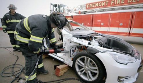
2

                                                                           Contents
Unit 1: What is Technology? ............................................................................................................................................... 3
   DEFINITIONS ................................................................................................................................................................... 4
   The Design Process ......................................................................................................................................................... 5
       Activity 1: Moveable toy or friendship card using templates and also split pins. ....................................................... 5
   Design considerations ..................................................................................................................................................... 8
       Activity 2 ................................................................................................................................................................... 10
       Activity 3 ................................................................................................................................................................... 11
Unit 2: Introduction to graphical communication ............................................................................................................ 11
       Practical Activity 4: Product packaging .................................................................................................................... 11
   Drawing conventions .................................................................................................................................................... 12
   Types of Lines ................................................................................................................................................................ 13
   Outlines ......................................................................................................................................................................... 13
   Construction Lines ......................................................................................................................................................... 14
   Hidden Details – Dotted Lines ....................................................................................................................................... 14
   Dimension ..................................................................................................................................................................... 14
   Scale .............................................................................................................................................................................. 15
   Graphic techniques: What is an oblique drawing? ...................................................................................................... 15
       Activity 5 ................................................................................................................................................................... 15
       Practical Activity 6 .................................................................................................................................................... 16
   Single vanishing point perspective ................................................................................................................................ 17
       Activity 7 ................................................................................................................................................................... 17
   Simple mechanisms: What are mechanisms? .............................................................................................................. 18
   What is a lever? ............................................................................................................................................................ 18
   Mechanical advantage ................................................................................................................................................. 20
       Activity 8: .................................................................................................................................................................. 21
   Linkage systems ............................................................................................................................................................ 21
       Activity 9: Identify the class of lever ......................................................................................................................... 23
   Pneumatics ................................................................................................................................................................... 25
   Hydraulics ..................................................................................................................................................................... 25
   Using pneumatics and hydraulics ................................................................................................................................. 25
       PRACTICAL ASSESSMENT TASK: PAT TERM 1 ............................................................................................................ 26

GM 2018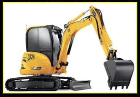
3

                    Unit 1: What is Technology?

Technology is the use of knowledge, skills, values and resources to meet people’s
needs and wants by developing practical solutions to problems, taking into consideration,
social and environmental factors. These solutions usually take the form of products.
Almost everything we use, from a pencil to a computer, is a product of technology.

Scope -Technology and the world of work
Technological skills and knowledge help to create different career paths and job
opportunities for people. Anyone who designs a product as part of their job does
Technology. For example, a chef who creates a new recipe does Technology. A
dressmaker who designs and makes a dress for weddings does Technology. We all use
technology. Many people use technology in the world of work. Examples of people who
work in Technology are artisans, engineers, surveyors, architects, graphic designers and
scientists.

                                Engineers

                                             Scientists

                                    Artisans

                                       Graphic Designers

                                Architects

                                             Surveyors

GM 2018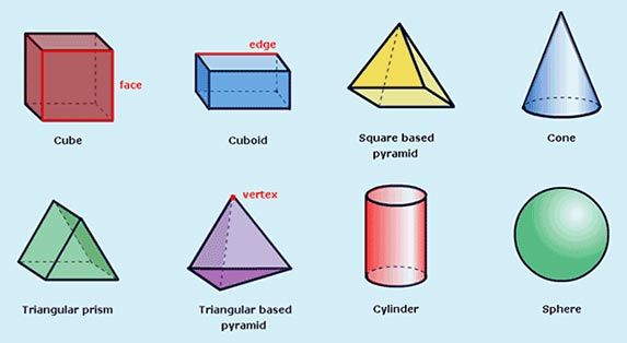
4

KEY WORDS:
   •    Technology – meeting people’s needs and wants.
   •    Design brief – a short statement that describes a need or problem.
   •    Design specifications – details about the product, such as its function and
        appearance.
   •    Constraints – things that limit your choices.
   •    Evaluation criteria – a set of questions about the design process and product.

                                       DEFINITIONS

 An engineer is a practitioner of                             Artisan is a worker in a skilled
 engineering, applying scientific                                trade, especially one that
 knowledge and mathematics to                                   involves making things by
 develop solutions for technical                                           hand.
           problems.

                                                           A Scientist is a person who
                                                            is trained in science and
                                                            whose job involves doing
       An Architect is a person                               scientific research or
       who plans, designs, and                             solving scientific problems.
             oversees the
       construction of buildings.

                                                        A land surveying professional
          A Graphic designer                            is called a land surveyor. They
         creates and combines                           determine the three-
          words, symbols and                            dimensional position of points
       images to create a visual                        and the distances and angles
        representation of ideas                         between them, like
        and messages through                            measurements on a road.
               visual art.

GM 2018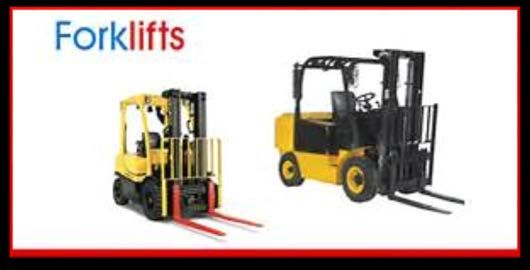
5

                                The Design Process

The design process is a set of steps we use when we plan how to make a product. The
steps in the design process enable you to develop solutions that solve problems. There
are five focus areas in the design process.
These steps are:
1) Investigate
2) Design
3) Make
4) Evaluate
5) Communicate

                                       Investigate

      Communicate
                                                                        Design
                                        Product

                                                                       Make
                   Evaluate

The diagram above shows the design process. The arrows show you that you can work
through the different focus areas in different ways and at different times. They also show
that you can return to a focus area after evaluating the technology.

   Activity 1: Moveable toy or friendship card using templates and also
                                        split pins.

INVESTIGATE and make a MOVEABLE TOY/ CARD using a template and split pins

Requirements: Cardboard, scissors, glue, split pins, colouring pencils and any other
materials, e.g. stickers.

GM 2018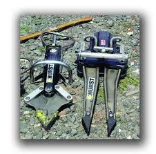
6

    Look carefully at the templates and images of TOYS AND CARDS. Follow the instructions
    on Worksheet 1 and then draw a toy, on cardboard, using the templates. Make sure you
    have enough cardboard left over to cut out parts of the toy that will be assembled using
    split pins.
•   Decorate your moveable toy or card.

    In our design process we are going to design a moveable card with an object using split
    pins and cardboard to cut out templates. We need to follow certain steps to design a
    moveable card. Use Worksheet 1 to complete this activity.

                                     Step 1: INVESTIGATE

    When you investigate, you gather information. You collect all the information you need to
    solve a problem. Then, you sort through the information and decide how you are going to
    use it. This process is called accessing (finding), processing (sorting) and using
    information. When you investigate, you need to keep a record of how and where you
    obtained your information. We call this acknowledging the information or referencing.

                                         Step 2: DESIGNING

    Once you understand a problem, you can start drawing up your design brief. A design brief
    is a short, clear statement that explains the problem and how to solve the problem.
    A design brief should include the following:
    •   What will you be making?
    •   How will it solve the problem?
    •   Any materials or resources needed

    GM 2018
7

After you have written your design brief, you should also list the specifications and
constraints for the project.

For example: Priyanka has nothing to hold her beautiful
flowers. Using creative thinking, a pair of scissors and some
paint, she changes a plastic bottle into a vase. The
specifications of a technology project list the requirements
that the solution must meet.

In our example, Priyanka would need to list the following specifications for her solution:
•   It needs to be able to hold a bunch of flowers.
•   It should be stable.
•   It needs to be waterproof.
•   It needs to be attractive to look at.

Constraints refer to anything that limits the designer when finding a solution to a problem.
Priyanka’s constraints could have been:
•   tools to make the vase
•   limited materials
•   no skills
•   time to make it

                                       Step 3: MAKING

After finalising your two initial rough freehand drawings, you should choose the best
design. Now, you do a detailed drawing of the product - this is your third drawing and 3D
design. Your final drawing should be neat, colourful, detailed and labelled.
The final design should include all details needed to make the product, including:
•   instructions
•   Dimensions/ measurements
•   materials needed
•   reasons for the choice you made

GM 2018
8

    Remember to draw up a step-by-step plan of how you intend on making your final product.
    You also need to list all the materials that you will need.

                                       Step 4: EVALUATING

     You should continually evaluate the design process to ensure a successful outcome. To
     evaluate means to consider or test something. You should evaluate whether you have
     identified the problem correctly. You should evaluate your design ideas. Here, you will
     make sure that your ideas meet all the specifications and constraints.

                                   Step 5: COMMUNICATING

•    You communicate through the design process.
•    This includes writing notes or making sketches.
•    Keep careful records of the components.
•    You may want to present your work on a poster or a presentation in your book.
     Another very useful way is a project report which contains all the notes and drawings for
     each step of the design process.

                                    Design considerations

     KEY WORDS:
        •   Fitness for purpose – a check that is performed
            on a product to ensure that it will meet the purpose for which it was designed.

     Everything that has ever been made was designed by someone. The first people on Earth
     were designing, even when they were making simple tools or shelter. Today, people make
     a career out of designing products and systems. When designing something, you need to
     consider a number of factors, which we refer to as design considerations. Let’s take a
     closer look at some of the design considerations you should keep in mind when designing
     a product or system.

     GM 2018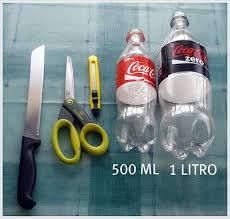
9

                                      WHO IS IT FOR?
 When you design your product or system, you always need to think of the people who
 will use it. We call this group of people your target group. For example, if you design a
 new chocolate –flavoured breakfast cereal, your target group might be children under 5.
 Or, if you design a new kind of beauty cream, your target might be women.

                                  WILL IT DO THE JOB?
 You need to evaluate your product or system to ensure that it does what it is set out to
 do. In other words, does it solve the problem or meet the need that you originally
 identified?

                                     WHAT IS IT FOR?
 You have to consider the purpose of the system or product. This will ensure that you
  can produce something that does what it is meant to do.

                                  IS IT COST EFFECTIVE?
 How much does the product cost to make?
 This will help you decide how much you can sell it for. Your product might solve a
 problem brilliantly and be perfectly suited to the people who need it, but be too
 expensive for those people to buy. So, you need to keep your costs down, but still
 produce something that is acceptable in terms of quality.

                                    IS IT EASY TO USE?
                                        (Ergonomics)
 Ergonomics is the study of designing products or systems that best suit fit for the
 human body. For example, some people sit for long hours in front of a computer.
 Therefore, they will want to sit in an office chair that is as comfortable as possible, but
 still suitable for computer work., so the office chair must have rotating wheels or an
 adjustable seat, for comfort.

                                  DOES IT LOOK GOOD?
Aesthetics is the study of how pleasing things are to look at.
GM 2018 are
 There        often many products that do the same job or serve the same purpose. In this
case, the shape, look and overall image of a product is what we look at.
10

                                       IS IT SAFE?
A product should be safe to use and should not harm the user, society or the
environment. You also need to consider the different people that will use the product.
Here, you need to think of people from minority groups or people with special needs, or
disabled people or elderly people or children.

                                          Activity 2

Read the pet shop owner’s problem below. Then answer the questions that follow.
                                  Step 1 – Design problem
The local pet shop owner has carried out a survey in which he found and saw a need for
automatic pet feeders when their owners go away on holiday.

                                    Step 2 – Design brief
Kaylee Naidoo is a pet shop owner who has been asked by her local customers to supply
an automatic animal /pet feeder. Some customers have holiday homes and go away on
weekends. They don’t always want to take their small pets such as dogs, cats, birds,
hamsters or mice with them because this is inconvenient. Small animals need very little
personal attention and can be left for short periods, as long as they are fed and sufficient
water is given.

                                         Questions

1. Name the product that needs to be designed.                                          (1)
2. Who is it for?                                                                       (1)
3. What is its purpose going to be?                                                     (1)
4. Suggest three things to ensure the product will be safe.                            (3)
5. Why is it important to ensure that the product looks good?                          (2)
6. State two ways you can ensure you don’t affect the environment negatively when
making your product.                                                                   (2)
                                                                                 Total: 10

GM 2018
11
Activity 3
In groups, discuss who does the work in the fields of technology listed below and write two
possible answers in your workbook.
Field of Technology Who does the work?
Medical
Construction
Farming
Education
Sports and Recreation
Mining
Unit 2: Introduction to graphical communication
Drawing your ideas is an important stage in the design process. You can use these
drawings to develop your ideas and tell others how to make the product you are designing.
This is known as graphical communication. Remember that a drawing needs to
communicate your ideas on paper. People who look at your drawings need to understand
what it is that you drew and why you drew it. So graphical communication is like a drawing
language.
What do we use graphics for?
Graphical communication involves sharing information and ideas using graphics. It’s easier
to explain an idea using a drawing than using words. We use drawings to jot down our
initial ideas - often as freehand sketches. These can be developed into working drawings,
3D (three-dimensional) oblique drawings, or even 3D artistic drawings.
Practical Activity 4: Product packaging
You will need:
• An empty package, such as a cereal box, a chips packet or a chocolate wrapper or any
empty packet of sweets.
• Your Technology workbook and your tablet.
GM 201812
What to do:
Read the questions and instructions, below, and answer the questions/locate (find) the
information by looking carefully at your wrapper or packet. You must write short notes
(rough copy) in your workbook to summarise the questions.
Open up a word document on your tablet and save it as follows: Your name, Activity 4.
Use your rough copy, or summarised notes, to type the information. (Number 9 must be
completed on A-4 white paper and must be pasted in your book.)
1) What is the name of the product you chose?
2) What brand does this product belong to?
3) Describe the logo of this brand.
4) What is the catch phrase used by this brand? Why would you buy it?
5) What does this catch phrase mean?
6) Describe the design of the product packaging.
Refer to its shape and size and the materials used to make it.
7) Can you think why the packaging was designed in this way?
8) Explain how you think the text, graphics and package design improve the product
appeal to consumers.
9) Draw the product package on a piece of white paper. Paste pieces of the wrapper or
package or part of it in your book.
• Show all the different elements of its design.
• Paste your drawing in your book.
Drawing conventions
KEY WORDS:
• Outlines – dark, continuous lines used as the outline of an object.
• Construction lines – thin, feint, continuous lines to construct other lines.
• Dimensioning – adding accurate measurements to a drawing.
• Hidden detail lines – dashed lines to show parts of an object.
GM 201813
Drawing provides a graphical language for communicating ideas and sharing information.
Designers use a standard set of rules called conventions when making drawings so that
they can be easily understood by everyone. Using these conventions, drawings are
described using lines, dimensions and angles.
Types of Lines
Designers use different types of lines to produce detailed line drawings of the products
they are designing.
These drawings can be free-hand sketches or 2D (two-dimensional) views. They are
drawn using accurate measurements so that engineers can use them to construct and
manufacture the items.
By convention, line drawings use three kinds of lines – outlines, construction lines and
hidden detail lines.
Outlines
______________________________________
• In 2D drawings, your outlines need to be thick and dark.
• They indicate the outline of an object, as well as all the parts that are visible from the
outside.
• Outlines can be straight or curved.
• You can use a dark 2H or 3H pencil or a black pen for outlines.
• Thick lines are normally used to show when one side of a 3D drawing is visible.
Width
A 3-D
Height pencil case
GM 201814
Construction Lines
• Construction lines are thin, continuous lines that are used to help construct other lines. In
2D and 3D drawings, these construction lines need to be thin and feint, which means they
are lighter in colour than outlines.
• Lines that join surfaces are also drawn using thin lines and construction lines can be
straight or curved.
Hidden Details – Dotted Lines
---------------------------
• Hidden detail lines are dashed lines. These lines are used to show the parts of the product
that are out of sight or hidden from view.
Dimension
Dimension means adding measurements to a drawing. Its purpose is to give a clear and
accurate description of the product that is to be made.
When you dimension a drawing you must follow these rules:
• The three main dimensions in a drawing are the width, depth and height.
• Dimension lines are continuous, light-coloured lines that are used to show the distance
between two points.
• At either side of the dimension lines are arrowheads.
• The dimensions are written above the dimension line.
• All measurements are in millimetres (mm).
• You can also draw two-dimensional (2D) drawings.
• These show the height and length of a shape or object.
You can also have drawings that are three
dimensional (3D). Three-dimensional drawings
have height, length and depth as in the examples
below.
GM 201815
Scale
When you draw an object, no matter how small or big, you need to draw it with the same
proportions as the original object. This is called scale drawing.
When someone sees your scale drawing, they will understand that you have:
• Measured the size of the real object.
• Reduced the measurements if it is a large object or enlarged them from small objects.
WE WRITE SCALE AS A RATIO:
Scale (the length in the drawing): the matching length in reality where 1mm means or
represents 10mm or scale is 1:10, or e.g. the scale of a car is 3600 mm but the scale
drawing is 20 times smaller, e.g. 1:20. (Refer to worksheet of car)
Graphic techniques: What is an oblique drawing?
An oblique projection is a way of drawing a 3D object in which the object is drawn with the
front view facing directly towards the observer, showing the true shape of the object. In an
oblique projection, circular features like round holes can be drawn on this front face as true
circles. In other types of 3 D drawings, circular features must be drawn as ellipses. To
show the 3D effect, parallel lines are drawn from the front face at an angle of 45º and are
joined to create the 3D shapes.
Activity 5
Drawing oblique drawings
You will need an H or HB pencil, 30 cm ruler, and a sheet of squared (quadrant) paper.
Use the given worksheet to draw a cube by following the steps below.
GM 201816
Follow these steps to make an oblique drawing:
• Measure the object that you will draw.
• Choose a scale for your object, e.g. 10 cm: 1 block (on the quadrant paper)
• Draw the front view of the object. Count out the correct number of blocks.
• Using the lines on the oblique paper, draw feint 45° lines to the back.
• These lines give your object depth.
• In oblique drawings, measure the depth lines to half their size.
• Count out half the squares for the depth of the object. Mark it.
• Complete the drawings by joining all horizontal lines.
Practical Activity 6
Free-hand sketches
As you begin to design a product or system, it is often helpful to make a few simple free-
hand sketches. Free-hand sketches can be 2D or 3D.
Follow these steps when making free-hand sketches:
Step 1: Use sharp pencils (HB) and paper
Step 2: Never push a pencil – always pull it.
Step 3: Keep your wrist and arm in contact with the paper or table at all times.
Step 4: Draw lines from left to right if you are right-handed. Draw lines from the right
to the left if you are left-handed.
Practise free-hand sketching by copying these drawings in your book:
Drawing 2: A television
Drawing 1: A shoe
GM 201817
Drawing 3: A doll Drawing 4: A car
Single vanishing point perspective
Single vanishing point perspective drawings make an object look more realistic. In these
drawings, the objects become smaller along lines called vanishing lines. These lines finally
meet at a point in the distance. This point is called the vanishing point (VP).
Single VP drawings use one vanishing point. The VP is always at eye level to the left or
right. Vertical lines are always drawn vertically.
Activity 7
Use the worksheet to draw a block with a single VP. Follow instructions on given
worksheet.
GM 201818
Simple mechanisms: What are mechanisms?
KEY WORDS:
• Mechanism – a set of moving parts that are used to make work easier.
• Lever – a simple mechanism made of a bar that turns around a fixed point.
• Fulcrum – the point of movement or pivot on which the arm of a lever moves.
A mechanism consists of a set of moving parts that are used to make work easier so that
we use less energy. Machines all contain mechanisms. For example, a bicycle is a
machine that uses mechanisms such as wheels and axles and gears to make it easier for
us to ride from one place to another.
What is a lever?
Think about when you used to play on the see-saw in the park when you were little. This is
an example of a simple machine called a lever.
A pair of scissors in figure 1, a stapler in figure 2, a pair of tweezers in figure 3 and a
wheelbarrow in figure 4 are familiar examples of levers. All of these levers are machines
that help to make our lives simpler.
Figure 1 Figure 2 Figure 3 Figure 4
How a lever works
• The fulcrum (pivot): This is the part where the lever will balance or turn.
• Load: This is the object that is being moved or lifted.
GM 201819
• Effort: This is the force that is used to move the load or the resistance with a board, a
handle or a bar that you can push or pull.
• When you push down with a force on one end of the lever, you are putting in effort. The
effort you put in will cause the other side of the lever to lift up, causing whatever was on
the other side to lift or move. The weight of the object you are trying to move is the load. A
small effort can move a large load when you use a lever.
First class levers: The fulcrum is between the effort and the load e.g. in a crowbar or a
see-saw. (F-E-L)
Figure 5 Figure 6
Second class levers: The load is now in the middle of the fulcrum and the effort, e.g. a
paper cutter and wheelbarrow. (F-L-E OR E-L-F)
Figure 7 Figure 8
Third class levers: The effort is in the middle of the load and fulcrum e.g. a rake and an ice
hockey stick. (L-E-F)
Figure 10
Figure 9
Mechanisms are not freestanding, but are found within structures. Mechanisms can only
work if one form or another of energy is exerted upon them.
GM 201820
We call this energy the input, which gets the process underway, and results in an output.
INPUT PROCESS OUTPUT
Example:
Let’s investigate the above with an example. Pick up your scissors. While you just look at
them, they can do nothing for you, but if you exert a force on them and push the two
handles together, you can cut paper. The power/ force that you use to push the handles
together is the input. The process is that the blades of the scissors move towards one
another and the output is the paper that is cut.
Mechanical advantage
The use of a lever gives one mechanical advantage. You are able to move or lift
something with the help of a lever that you wouldn’t be able to without a lever. The
advantage is determined by the length of the bar (lever), the position from the fulcrum and
the position from the force and the load. What happens if you change the distance
between the fulcrum and the force?
GM 201821
The screwdriver acts as a lever that can take a lid off a tin of paint. If you use a short
screwdriver to open a very tight lid and then use a longer screwdriver, what do you think
the difference will be?
The screwdriver lever helps you to open the tin because it multiplies the force or effort that
you place on the screwdriver. A lever multiplies the force it applies to a load through
something called mechanical advantage. A mechanism gives us a mechanical advantage
by multiplying the input force applied to a mechanism into a much greater output force.
Activity 8:
How to work out the mechanical advantage (MA):
MA = load ÷ force
In this example:
MA = 600N ÷ 100N
= 6 The mechanical advantage is 6. The greater the mechanical advantage, the
more the lever helps you. Now try the following to work out the MA.
1) 12000 ÷ 40=
2) 450 ÷ 3=
3) 945 ÷ 5=
4) 678 ÷ 3=
5) 12000 ÷ 80=
Linkage systems
KEY WORDS:
• Linkage – two or more levers that are joined.
• Paired link lever – two levers that are joined, and work together.
• Complex linkage – a number of levers joined together.
A linkage is made of two or more levers that are joined. We call two levers that are joined
paired or linked levers. With a linkage system, one or more of the rods will have a fixed
GM 201822
pivot around which it moves and the other rods will be joined with moving pivots. Linkages
are used to:
1. Change the direction of movement;
2. Change the distance of movement;
3. Allow parts to move parallel to one another;
4. Allow two or more items to move at the same time.
Examples where linkages are used:
Linkages are used as indicated below:
To view more linkages and mechanisms and how they work, type the following hyperlink:
www.technologystudent.com/cams/link1.htm
Linkages and first- class levers
The fulcrum is in the centre of a first- class lever system. A fulcrum is a pivot or support.
Examples are: a pair of scissors (figure 1) pair of pliers (figure 2), a hedge-trimming
shears (figure 3)
Figure 1 Figure 2 Figure 3
GM 201823
Linkages and second-class levers
The hole or paper punch has been around for many years. Benjamin Smith patented and
improved the hole punch in 1885. The single hole punch made only one hole. Single hole
punches are still used today and are very useful, especially for technology.
Images of a single- hole punch.
Many years later, the punch you find in schools and offices was developed. This is a
double punch, designed to punch two holes at once. The paper can then easily be filed
into a ring-binder file.
Image of a double- hole punch
Linkages and third -class levers
Third-class levers are quite common. Remember, a third-class lever
cannot give you mechanical advantage. This means that the force that
you apply is always going to be greater than the load. You can use
third-class levers to pick up objects. For example, tweezers are used
to pick up really small objects. Another example of a third-class lever is
the staple remover. If you have ever tried taking a staple out of a thick
book, the staple remover helps you to do this job more easily.
Activity 9: Identify the class of lever
Carefully study the pictures of different levers below and write the answers in your book.
1.
2.
GM 201824
4.
3.
5.
6. 7.
8.
9.
1) Identify where the load, the effort/ force and the fulcrum is in each picture.
2) Write this in the format as shown above using arrows to show how the lever works. For
example: load → effort/force → fulcrum / (L-E-F)
3) Now identify the class of lever in each case.
4) Make a symbolic drawing for each. Use a symbol, e.g. a triangle.
View the power point presentation on
Hydraulics and pneumatics and how this works
Grade 7 Technology
GM 201825
Pneumatics
Pneumatics or pneumatic systems are machines that are compressed air or gas. The air in
pneumatic systems is compressed with a pump. When you push on the handle of a bicycle
pump, for example, you are compressing the air and forcing it into a smaller space.
Compressed air enter the base of a pneumatic cylinder it pushes on the piston and makes
the piston rod extend. Air on the other side of the piston escapes into the atmosphere.
When compressed air enters the rod end of a pneumatic cylinder it makes the rod retract.
Click on the following hyperlink to watch a video explaining more about hydraulics and
pneumatics: www.youtube.com/watch?v=YlmmRa-9zDF8
Hydraulics
Hydraulic systems use liquids such as oil and water, to work machinery. Liquids are used
because theyare incompressible and can’t be squashed. In a hydraulic system oil replaces
compressed air to transmit motion and force. On any construction site or repair centre you
will see hydraulically worked machinery in the form of bulldozers, front-end loaders,
forklifts and a car lift.
Using pneumatics and hydraulics
Pneumatics and hydraulic systems do the same thing as levers- it makes the work easier
for us by multiplying a force. Many of them are able to lift incredible loads with just small
effort.
A hydraulic car jack can lift a heavy car.
Hydraulic and pneumatic systems basically work in the same way. The only difference is
that hydraulics uses an incompressible liquid (such as oil), while pneumatics uses
compressed air.
GM 201826
As you prepare to design and make your Jaws-of-Life system, you will need to practically
investigate how pneumatic and hydraulic systems give us a mechanical advantage.
The following investigations on how pneumatic and hydraulic systems work will be done
practically.
PRACTICAL ASSESSMENT TASK: PAT TERM 1
TOPIC: Mechanical systems and control
CONTEXT: JAWS-OF-LIFE: Rescue system
CONTENT: levers, linkages, hydraulics, pneumatics.
KEY WORDS:
• Pneumatic system – a mechanical system that uses compressed air to do tasks
such as make things move.
• Hydraulic system – a mechanical system that uses liquids under pressure to do
tasks such as make things move.
• Force – an influence that can move an object, usually a push or pull.
GM 201827
The problem scenario
The motor car is an invention that has had major influence on society. People are able to
travel greater distances than before, and are able to do so faster and far more comfortably.
But the motor car has also had a negative effect on society. In South Africa, more than
14 000 people die in car accidents every year.
In our holiday seasons, many South Africans travel on our major highways to holiday
destinations. They set off excited and enthusiastic about a few days of holiday and rest.
Sadly, because of the number of cars on the road, accidents happen. Sometimes, people
are trapped in a car and cannot get out. A useful machine that helps us to rescue people in
this situation is the Jaws-of –Life system.
Have you ever tried to cut through 8-10 sheets of paper or a thick piece of cardboard? If
you have, you will know how difficult this is to do. You need to apply a lot of force to the
scissors to cut through these objects because they are so thick. Cardboard is very thick
and not easy to cut at all.
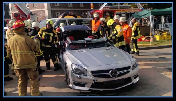
Emergency rescue workers often need to cut through the frame of a car or twisted
wreckage to free victims of accidents. A car frame is extremely thick, so they need very
special tools. They usually use special hydraulic cutters called Jaws-of-Life. These cutters
look like metal jaws. The Jaws-of-life is made of several types of piston-rod and hydraulic
parts, such as cutters, spreaders and reams. One of the uses is to force open vehicles
involved in accidents.
The hydraulic cutter consists of two basic parts: the lever system at the front and the
hydraulic system at the back. The blades of the cutter are linked levers.
A black rubber protective sheath covers the moving parts to make it safe for the operator
to use. Underneath the sheath are more linked levers. These, push the blades closed, at
the front of the hydraulic cutter.
Use the following links to find more information or images.
www.jawsoflife.com/
www.howstuffworks.com/car-driving-safety/accidents
www.youtube.com/watch?v=OmWncPNzmv4
GM 201828
Requirements for the Jaws-of-Life system
• Base it on levers and linkages.
• It should be powered by a hydraulic-syringe system.
• Make the system using available materials, such as cardboard or wooden ice-cream
sticks, new syringes (without needles), tubing and nuts and bolts.
• The linkages should be able to move smoothly. The effort to move the linkages should
come from the hydraulic system.
Something interesting
The first Jaws-of-Life tool was first used in 1963 to rescue racing car drivers. It was
transported on the back of a pick-up truck because it was so big! Since then, these tools
have been refined and improved, but we continue to use this name to refer to all hydraulic
rescue tools.
Designing a rescue system
Write a design brief, by using a list of questions, to list the specifications and constraints
for your jaws-of-life system. Make a simple working model using available materials.
Questions can include:
• What is it that I have to make?
• What is it used for?
• How big does it need to be?
• What will it be made from?
• What tools do I need to be able to make it?
• How much will it cost to make the model?
GM 201829
Before you write your design brief, write down exactly what it is you have to do to solve the
problem. Constraints are the things that limit your choices for solving the problem. They
include the things that you must do or use when you make the solution, as well as the
things that you may not do or use to make the solution. For instance, constraints could be:
• The materials you may or may not use
• The tools you may or may not use
• The time you have to complete the task.
Now, plan and write a design brief for your model.
After drawing two freehand (rough) sketches, you need to make a clear and precise 3D
drawing in oblique projection to show how you will design your hydraulic rescue tool. Make
sure you use the correct conventions, especially dark and feint lines where necessary.
Make working drawings in 2D that show one view of your hydraulic rescue tool. Include the
dimensions to scale.
• Make a list of all the materials you will need.
• Make a list of all the tools you will need.
• Make notes on your decisions.
• List any safety precautions you might need to consider when making your Jaws-of-life
system.
GM 201830
How to make a pneumatic system
You will need three plastic syringes without needles – two of equal volume and one
smaller one; a short length of plastic tubing which fits snugly over the ends of each
syringe; a bowl of water, a matchbox filled with a few stones; a ruler.
Pull out the plungers from the two equal-sized syringes until they are both halfway up the
syringe chambers. Connect the syringes using the plastic tubing. This is a pneumatic
system, because the syringes are both filled with air.
Investigate:
1. Hold your thumbs on both plungers, and apply pressure to one of the plungers. This is
the input plunger. What do you feel? Repeat this using the other plunger as the input
plunger. Record your results in your workbook.
2. Place the matchbox on your measuring sheet, to the right of the line. Align the edge of
the matchbox with this line. Push the plunger of one of the syringes all the way in, and
place its plunger against the right hand edge of the matchbox. The other syringe will
have its plunger out.
3. Push the plunger that is out. That is the input syringe. Observe what happens when
you do this.
GM 201831
4. When you push down the plunger, force is transferred from the input syringe to the
output syringe. It should move the matchbox leftwards, over the line.
How to make a hydraulic system
Pull out the plungers from the two equal-sized syringes. Place them in a bowl of water, so
that the syringe chambers fill up with water. Working under water, push the plungers into
the syringes until they are halfway up the syringe chambers. Put the tubing under the
water, and connect the ends to both syringes, making sure that there is no air in the
system. This is a hydraulic system, because both syringes and tubing are filled with water.
Now, have fun designing your own Jaws-of-life simple model and the drawing of the
images for your first PAT (Practical Assessment Task). Use the printed worksheets and
rubrics to complete the activities.
GM 2018You can also read