Bridge Railing Manual - Version 1.1 - Maryland State Highway Administration
←
→
Page content transcription
If your browser does not render page correctly, please read the page content below
Bridge Railing Manual

Version 1.1                    Last Modified: March 9, 2021
Version                               Update from Previous Version
          Section 1.3 updated to include additional clarifying information regarding Standard
          No. 26. Section 2.7 updated to include guidance on the treatment of existing bridge
  1.1
          rail and guidance on existing structure protection. Section 4.2 updated to reflect SHA
          crash testing.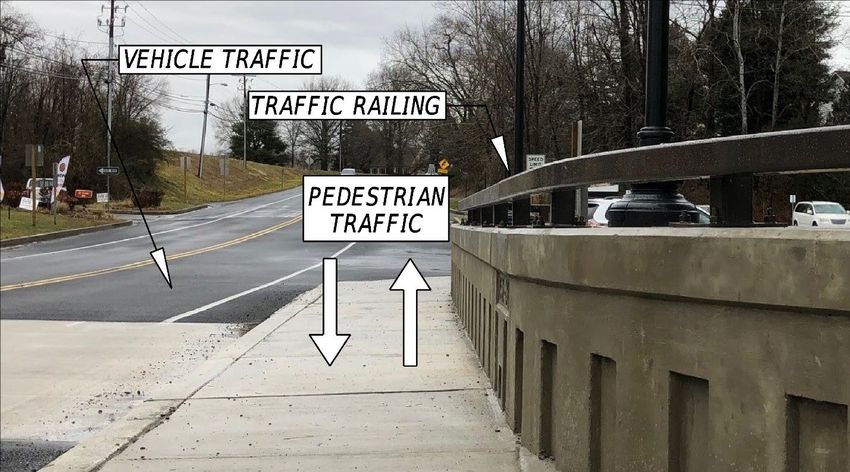
Bridge Railing Manual

Table of Contents
Chapter 1 Introduction .............................................................................................................................. 1-1
   1.1 Crashworthy Requirements ............................................................................................................. 1-1
   1.2 Barrier Strength Selection ................................................................................................................ 1-2
   1.3 Bridge Rail Limits .............................................................................................................................. 1-3
Chapter 2 Design Considerations .............................................................................................................. 2-1
   2.1 Bridge Users ..................................................................................................................................... 2-1
   2.2 Bridge Railing Applications............................................................................................................... 2-1
   2.3 Bridge Rail Ends ................................................................................................................................ 2-4
   2.4 Fencing ............................................................................................................................................. 2-6
       2.4.1 Fencing Locations ...................................................................................................................... 2-6
       2.4.2 Fence Post Spacing .................................................................................................................... 2-7
   2.5 Bridge Rails on Retaining Walls ........................................................................................................ 2-7
   2.6 Bridge Rail Selection Coordination .................................................................................................. 2-9
   2.7 Existing Structures............................................................................................................................ 2-9
       2.7.1 Treatment of Existing Bridge Rail .............................................................................................. 2-9
       2.7.2 Existing Structure Protection .................................................................................................. 2-12
Chapter 3 Bridge Rail Selection ................................................................................................................. 3-1
   3.1 MDOT SHA Bridge Rails .................................................................................................................... 3-1
   3.2 Use of Bridge Rails other than MDOT SHA Bridge Rails ................................................................... 3-7
Chapter 4 Temporary Barriers .................................................................................................................. 4-1
   4.1 Design Considerations...................................................................................................................... 4-1
   4.2 MDOT SHA Standard Low Deflection Applications .......................................................................... 4-3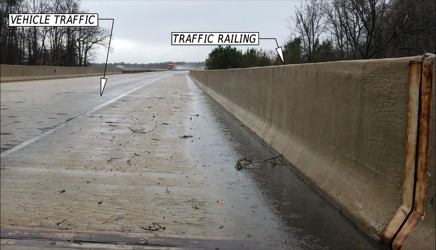
Bridge Railing Manual

Chapter 1 Introduction
The Maryland Department of Transportation has developed this Bridge Railing Manual to document
national policy and practice and to emphasize standards and practices that have proven successful in this
state. This manual applies to all Maryland Department of Transportation State Highway Administration
(MDOT SHA) administered contracts as well as all contracts receiving federal funding through MDOT SHA.
This manual incorporates guidance that is currently found in the following National publications and
references:
    • The 2018 AASHTO A Policy on Geometric Deign of Highways and Streets;
    • The 2016 AASHTO Manual for Assessing Safety Hardware;
    • The 2011 AASHTO Roadside Design Guide;
    • The 2004 AASHTO Guide for the Planning, Design, and Operation of Pedestrian Facilities;
    • The 2017 AASHTO LRFD Bridge Design Specifications;
    • Various Research Reports; and
    • Guidance contained in memos and letters published by the FHWA.

As this manual is applied throughout the design process, it is critical for the designer to always be
cognizant and to actively consider the principles of the forgiving roadside environment. The forgiving
roadside environment concept was first introduced by AASHTO in 1974 in the second edition of their
Highway Design and Operational Practices Related Highway Safety Manual. The two most important
principles of the forgiving roadside environment that apply to this manual are as follows:
    1. Provide errant vehicle with an opportunity to regain control before striking a fixed object along
        the roadside.
    2. The traffic barrier which is installed to shield an obstruction must be less hazardous than the
        obstruction which it is meant to protect.

In the context of creating a forgiving roadside, The AASHTO Roadside Design Guide documents an order
of preference for reducing roadside obstacles as follows:
     1. Remove the obstacle.
     2. Redesign the obstacle so it can be safely traversed.
     3. Relocate the obstacle to a point where it is less likely to be struck.
     4. Reduce the impact severity by using an appropriate breakaway device.
     5. Shield the obstacle with a longitudinal traffic barrier designed for redirection or use a crash
        cushion.
     6. Delineate the obstacle if the previous alternatives are not appropriate.

1.1 Crashworthy Requirements
All traffic railings that are constructed on MDOT SHA administered contracts as well as all contracts
receiving federal funding through MDOT SHA shall be structurally and geometrically crashworthy for the
application in which they are applied. In addition, the traffic barrier system must either be transitioned
to an acceptable highway approach traffic barrier or continued to a point where it can be safely
terminated off the structure.

Roadside safety first came into focus in the 1960s. The first documented procedures for full-scale vehicle
crash testing were contained in Highway Research Correlation Services Circular 482 which was a one-page
paper published in 1962. In an August 28th, 1986 memo, the Federal Highway Administration (FHWA)

1-1: Introduction                                                           Last Modified: March 9, 2021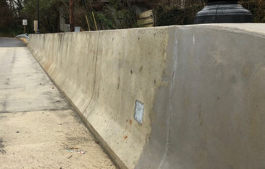
Bridge Railing Manual

issued a policy requiring that all bridge rails that are used on the National Highway System (NHS) or the
Interstate Highway System (IHS) must be crash tested. In the time since, crash testing procedures and
guidelines as well as FHWA requirements and policies have changed multiple times, however, the
importance of crash testing has remained a constant.

In 2009, AASHTO published the Manual for Assessing Safety Hardware (MASH) which superseded NCHRP
Report 350 Recommended Procedure for Safety Performance Evaluation of Highway Features as the
guidelines for roadside safety hardware performance evaluation. In 2016, AASHTO published the second
edition of the MASH manual as well as agreed to a joint implementation agreement with the FHWA. The
joint implementation agreement outlined the sunset dates for NCHRP Report 350 compliant roadside
safety hardware and the sunrise dates for MASH 2016 compliant roadside safety hardware for work
performed on the NHS. The January 7th, 2016 agreement stated that all “bridge rails, transitions, all other
longitudinal barrier (including portable barriers installed permanently), all other terminals, sign supports,
and all other breakaway hardware” would be MASH 2016 compliant for contracts let after December 31st,
2019.

On May 26, 2017, the FHWA issued an open letter to the states which stated that “The FHWA’s Federal-
aid eligibility letters are provided as a service to the States and are not a requirement for roadside safety
hardware to be eligible for federal-aid reimbursement.” This letter also went on to state, “Since its official
launch questions about the AASHTO MASH criteria have been identified by a range of stakeholders. Until
such time these questions are answered and the transportation community has more experience with
AASHTO MASH requirements, FHWA will require manufacturers and States to run all AASHTO MASH
recommended crash tests in order to qualify for a FHWA Federal-aid eligibility letter.” In addition, a letter
from the FHWA to its Division Administrators issued on April 9, 2018 stated that “An eligibility letter is not
a requirement for roadside safety hardware to be determined eligible for Federal funding. Roadside
safety hardware is eligible for Federal funding if it has been determined to be crashworthy by the user
agency (i.e. State DOT).” This manual is intended to document the bridge railings which are considered
crashworthy by the Maryland Department of Transportation.

1.2 Barrier Strength Selection
The barrier application that is selected for installation should be selected based upon the Test Level (TL)
criteria established in the latest edition of the MASH manual. The MASH manual currently defines six
different Test Levels for longitudinal barriers. It is important to note that bridge rails are included in
MASH’s longitudinal barrier designation. The recommended Test Matrices for longitudinal barriers are
described in Figure 1-1.

1-2: Introduction                                                              Last Modified: March 9, 2021
Bridge Railing Manual

             MASH Test                                               Impact            Impact Angle       Acceptable Impact
Test Level                           Test Vehicle
               No.                                                 Speed (mph)           (degrees)         Severity (kip-ft)
               1-10             Passenger Car 2420-lb                  31                   25                   ≥13
    1
               1-11              Pickup Truck 5000-lb                  31                   25                   ≥27
               2-10             Passenger Car 2420-lb                  44                   25                   ≥25
    2
               2-11              Pickup Truck 5000-lb                  44                   25                   ≥52
               3-10             Passenger Car 2420-lb                  62                   25                   ≥51
    3
               3-11              Pickup Truck 5000-lb                  62                   25                  ≥106
               4-10             Passenger Car 2420-lb                  62                   25                   ≥51
    4          4-11              Pickup Truck 5000-lb                  62                   25                  ≥106
               4-12          Single-Unit Truck 22,000-lb               56                   15                  ≥142
               5-10             Passenger Car 2420-lb                  62                   25                   ≥51
    5          5-11              Pickup Truck 5000-lb                  62                   25                  ≥106
               5-12         Tractor-Van Trailer 79,300-lb              50                   15                  ≥404
               6-10             Passenger Car 2420-lb                  62                   25                   ≥51
    6          6-11              Pickup Truck 5000-lb                  62                   25                  ≥106
               6-12         Tractor-Tank Trailer 79,300-lb             50                   15                  ≥404
                                    Figure 1-1: MASH Test Matrix for Longitudinal Barriers

    Figure 1-2 summarizes the guidance that the 2017 AASHTO LRFD Bridge Design Specifications, 8th Edition
    provides on selecting the appropriate Test Level criteria for a bridge rail application.

Test Level                                               AASHTO Guidance
             Taken to be generally acceptable for work zones with low posted speeds and very low-volume, low-
  TL-1
             speed local streets.
             Taken to be generally acceptable for work zones and most local and collector roads with favorable
  TL-2       site conditions as well as where a small number of heavy vehicles is expected and posted speeds are
             reduced.
             Taken to be generally acceptable for a wide range of high-speed arterial highways with very low
  TL-3
             mixtures of heavy vehicles and with favorable site conditions.
             Taken to be generally acceptable for the majority of applications on high-speed highways, freeways,
  TL-4
             expressways, and Interstate highways with a mixture of trucks and heavy vehicles.
             Taken to be generally acceptable for the same applications as TL-4 and where large trucks make up a
  TL-5       significant portion of the average daily traffic or when unfavorable site conditions justify a higher level
             of rail resistance.
             Taken to be generally acceptable for applications where tanker-type trucks or similar high center of
  TL-6
             gravity vehicles are anticipated, particularly along with unfavorable site conditions.
                                          Figure 1-2: Test Level Selection Guidance

    1.3 Bridge Rail Limits
    All MDOT SHA administered contracts as well as all contracts receiving federal funding through MDOT
    SHA shall protect adjacent roadside hazards in accordance with the AASHTO Roadside Design Guide and
    with the guidance that is contained in this manual. For purposes of this manual, structures have been
    categorized into four different applications based upon how protection of adjacent hazards should be
    considered:

    1-3: Introduction                                                                        Last Modified: March 9, 2021
Bridge Railing Manual

    •   Bridges – These structures are required to use bridge railing in accordance with this manual along
        the full length of the structure. MDOT SHA requires that all permanent bridge railing on high-
        speed roadways meet the requirements of a TL-5 bridge railing with the exception of locations
        where an open rail is desired for aesthetic purposes or where a TL-5 rail cannot be installed due
        to accelerated bridge construction techniques. At these exception locations on high-speed
        roadways, a TL-4 compliant bridge rail may be installed. For purposes of this discussion, a high-
        speed roadway is defined as any roadway where the higher of either the design speed or the
        posted speed is 50 mph and above. The bridge rail end as well as any other associated slopes
        which require protection should be protected as required by this manual and the AASHTO
        Roadside Design Guide.
    •   Roadways elevated through use of retaining structures – These structures require that bridge
        rail be installed along retaining walls where fall off protection is required. MDOT SHA requires
        that all permanent bridge railing on high-speed roadways meet the requirements of a TL-5 bridge
        railing with the exception of locations where an open rail is desired for aesthetic purposes or
        where a TL-5 rail cannot be installed due to accelerated bridge construction techniques. At these
        exception locations on high-speed roadways, a TL-4 compliant bridge rail may be installed. For
        purposes of this discussion, a high-speed roadway is defined as any roadway where the higher of
        either the design speed or the posted speed is 50 mph and above. Section 2.5 of this Manual
        provides information about the application of bridge rail along these elevated roadways. The
        bridge rail end, as well as any other associated slopes which require protection, should be
        protected as required by this manual and the AASHTO Roadside Design Guide.
    •   Structures between 18’-6” and 40’-0” – If geometrically feasible, these structures should provide
        bridge railing in accordance with this manual along the full length of the structure, however, on
        structures carrying very low mixtures of heavy vehicles and where the distance between the
        normal termination point of thrie beam on the approach and trail ends is between 18’-6” to 40’-
        0” the thrie beam can be carried across the entire parapet face. In these cases, the inside face of
        the concrete barrier shall be notched to receive the thrie beam so that its face is even with that
        of the face of the concrete barrier. Transition to W-beam traffic barrier off both ends of the
        barrier.
    •   Buried structures or structures shorter than 18’-5” – These structures are small structures where
        it is preferable to use traditional W-beam traffic barrier to protect the adjacent roadside hazard
        (typically fall off protection or protection from blunt concrete end walls). If the structure is deep
        enough, W-beam traffic barrier can be installed above the structure. If the structure is too shallow
        to allow for the installation of W-beam traffic barrier above the structure, then the structure could
        be spanned with a long-span traffic barrier system in accordance with MDOT SHA’s Book of
        Standards – For Highway & Incidental Structures, Standard No. 605.26 entitled “Traffic Barrier W
        Beam Post Placement Details for Spanning 12’-2” to 18’-5” Openings”. Unlike past versions of
        Standard No. 605.26, the current standard does not require nesting the rail.

1-4: Introduction                                                             Last Modified: March 9, 2021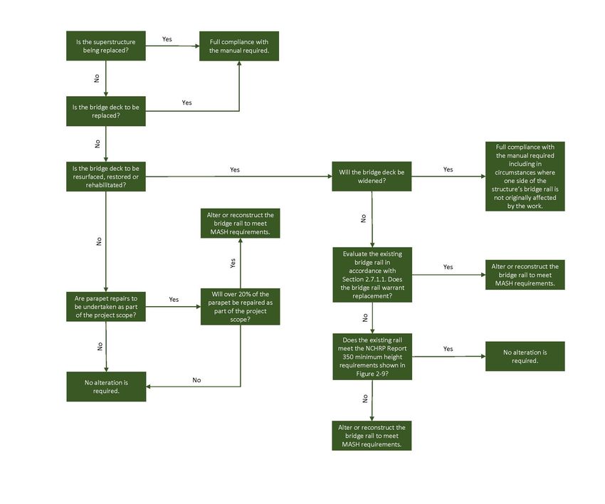
Bridge Railing Manual

Chapter 2 Design Considerations
This chapter is intended to provide guidance on several design considerations associated with the
placement of bridge railing.

2.1 Bridge Users
When bridge railing is to be installed, the designer must consider the bridge rail users and their unique
requirements and characteristics. For purposes of this manual, roadway users have been broken into
three categories based on their unique design requirements and needs:
    • Vehicle Traffic – this category includes all motorized vehicles. Vehicular traffic can be further
        broken down based upon the AASHTO Manual for Assessing Safety Hardware defined Test Level
        criterion.
    • Pedestrian Traffic – this category includes all pedestrian users. It is also important to note that in
        accordance with the American’s with Disabilities Act (ADA), any bridge that can be accessed by
        those with disabilities must be designed to meet current ADA requirements.
    • Bicycle Traffic – this category includes all bicycle users.

2.2 Bridge Railing Applications
The Maryland Department of Transportation defines four different bridge rail applications based upon
their installation configurations. The four different bridge rail applications that MDOT SHA recognizes are
described below:
    • Traffic Railing – A traffic railing is a bridge railing that has been designed and crash tested to
         withstand vehicular impact loading. This bridge railing type is to be used adjacent to vehicular
         traffic on bridges. The traffic rail that is selected shall be crashworthy for the design traffic which
         will utilize the facility.
    • Pedestrian Railing – A pedestrian railing must be used adjacent to all pedestrian walkways on
         bridge structures. The pedestrian railing must meet the requirements contained in the AASHTO
         LRFD Bridge Design Specifications manual for both height and clear-opening criteria. The AASHTO
         LRFD Bridge Design Specifications manual requires that all pedestrian railing must be a minimum
         of 42” (3’-6”) in height measured from the top of the walkway. The clear opening between
         horizontal and vertical members of the pedestrian bridge railing must be small enough to not
         allow a 6” diameter sphere to pass through the bottom 27” of the railing. Above this 27” height,
         the clear opening shall be small enough that it shall not allow an 8” diameter sphere to pass
         through the railing. A safety toe rail or curb should also be provided. Note, most pedestrian
         railings have not been crash tested and have not been designed to withstand vehicle impact loads.
    • Bicycle Railing – A bicycle railing must be used on all bridges that are specifically designed to carry
         bicycle traffic and at locations where a significant portion of the traffic using the facility will be
         bicycle traffic. The height of the railing as well as the openings of the railing shall conform to the
         guidance provided in the Pedestrian Railing section.
    • Combination Railing – A combination railing is defined as a bridge railing which meets the
         requirements of both a traffic railing and either a pedestrian or bicycle railing. A combination rail
         is typically installed behind a raised curb and sidewalk. Combination rails installed behind a raised
         curb are only used on low-speed roadways which are defined as a roadway with either the higher
         of the design speed or the posted speed being 45 mph or below.

2-1: Design Considerations                                                      Last Modified: March 9, 2021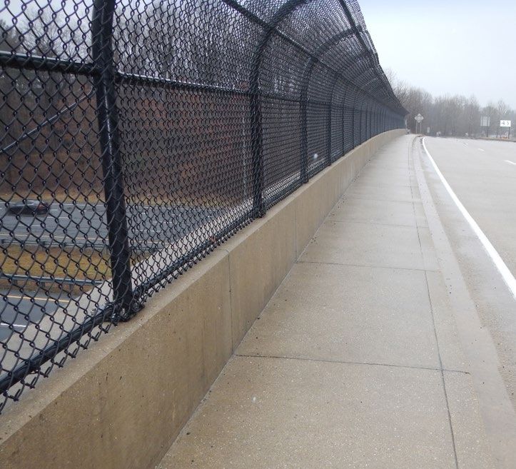
Bridge Railing Manual
Figure 2-1 to Figure 2-3 visually describe the various configurations of bridge rail applications. MDOT
SHA’s standard bridge railing is documented in Chapter 3 of this manual.
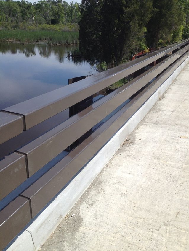
Figure 2-1: Roadway with No Pedestrian Facilities
Figure 2-1 depicts traffic railing installed adjacent to vehicle traffic on a roadway where there are no
pedestrian accommodations. The traffic railing should be selected based on the requirements contained
in this section as well as Section 1.2 and Section 1.3.
2-2: Design Considerations Last Modified: March 9, 2021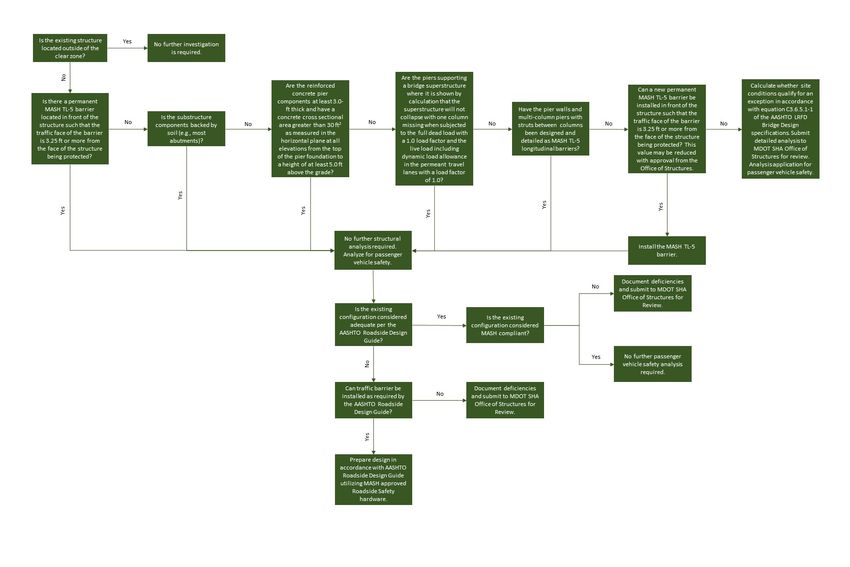
Bridge Railing Manual

                              Figure 2-2: Low-Speed Roadway with Pedestrian Facility

Figure 2-2 depicts bridge railing installed behind a raised curb on a low-speed roadway where there are
pedestrian accommodations. The bridge railing that is installed must be a combination rail which acts as
both a traffic railing and either a pedestrian or bicycle railing. The minimum offset distance of 5’-8”
between the face of the curb and the railing face is a critical dimension and should not be violated. If this
dimension must be violated, then proper justification must be provided to the Office of Structures for
approval.

2-3: Design Considerations                                                             Last Modified: March 9, 2021
Bridge Railing Manual
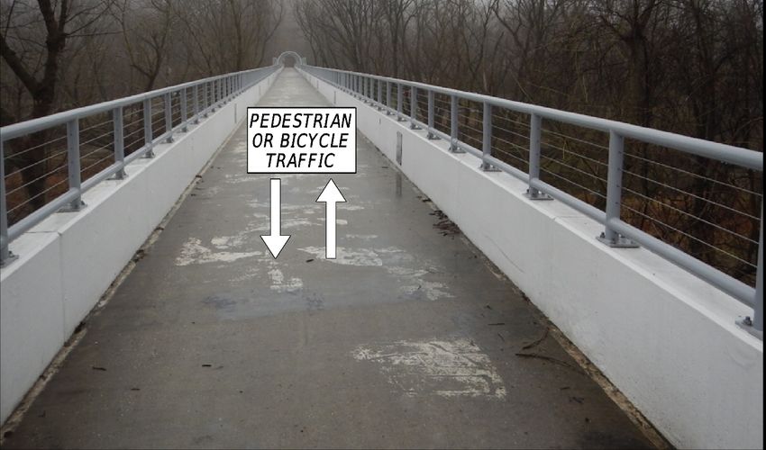
Figure 2-3: Pathway Designated for Non-Vehicular Traffic
Figure 2-3 depicts pedestrian or bicycle railing installed on a bridge where vehicular traffic is prohibited
and therefore, traffic railing is not required.
2.3 Bridge Rail Ends
The end of a bridge rail adjacent to the traveled way presents a roadside hazard which must be made
crashworthy in accordance with this manual as well as the guidance contained in the AASHTO Roadside
Design Guide. Any bridge rail end location that deviates from the requirements of this manual must
submit a proposed solution or mitigation to the Director of the Office of Structures for approval.
The most common and effective way to protect the end of a bridge rail is to connect the bridge rail to the
adjacent barrier leading up to the structure. When the bridge rail is connected to an adjacent W-beam
traffic barrier, it is essential to install a proper stiffness transition between the two systems as well as to
transition the shape and size of the bridge rail to ensure crashworthiness of the system.
A stiffness transition is required to produce a gradual stiffening of the system to eliminate vehicular
pocketing, snagging, or penetration. The bridge rail shape and size must also be transitioned to reduce
any potential snag points or any abrupt changes in geometry which could affect the rail’s crashworthiness.
Crash testing has shown that these transition locations are sensitive systems and therefore, when a
crashworthy stiffness transition is required at the end of the bridge rail, the stiffness transition as well as
the end post layout shall conform to the MDOT SHA detail for the bridge rail application. Chapter 3 of this
2-4: Design Considerations Last Modified: March 9, 2021Bridge Railing Manual
manual provides a description of the end posts as well as the stiffness transitions that shall be used on
each bridge rail application.
A crashworthy stiffness transition shall be installed on all approach ends to the bridge rail and on the trail
end of the bridge rail on all conventional undivided two-way roadways. The trail end stiffness transition
should then connect to a crashworthy and appropriate end treatment. On divided one-way roadways, a
stiffness transition to protect the trail end of the bridge rail is not required unless there are mitigating
circumstances present.
For structures carrying two-way traffic with no traffic barrier on the approach roadway and aesthetics is
of concern, consider tapering the end post barrier on all four ends, away from the highway until the offset
is beyond the clear graded area where a traffic barrier would no longer be warranted based on the flare
rate requirements of the AASHTO Roadside Design Guide. This application is shown below as Figure 2-4.
If aesthetics is not a main feature of the bridge, the appropriate stiffness transitions noted above and end
treatments shall be included on all four ends.
Figure 2-4: Tapered End Posts at Locations where Aesthetics is a concern and there is no Adjacent Traffic barrier
At location where sidewalk is installed adjacent to an end post, consideration must be given to the
treatment of the sidewalk and end post. Where there is adjacent W-beam traffic barrier, maintain the
sidewalk width with no offset between the sidewalks and curb for 25’ minimum beyond end of end post.
Where there is no traffic barrier on the adjacent highway, an option when right-of-way is available is to taper
the parapet away from the highway (25’ minimum taper length) until the offset is 10’ minimum on approach
and trail ends.
2-5: Design Considerations Last Modified: March 9, 2021Bridge Railing Manual
2.4 Fencing
Fencing or protective screenings should be placed on top of certain structures to prevent individuals from
throwing debris from the structure. Maryland State Highway Administration maintains details for
attaching fencing to bridge traffic barrier in Category 4, Chapter 3 of MDOT SHA’s online version of the
Book of Standards – For Highway & Incidental Structures. Fencing shall be added to structures in
accordance with Section 2.4.1 of this manual. Fence posts shall be spaced in accordance with Section
2.4.2 of this manual.
2.4.1 Fencing Locations
Fencing can affect a system’s performance and crashworthiness and should only be placed where
absolutely needed. Fencing or protective screening shall be added to structures in accordance with Figure
2-5. Use anti-climb shields at locations as needed.
Fencing Application MDOT SHA Guidance
A bridge shall contain fencing when there is a roadway or pedestrian facility
underneath. If the bridge is on a controlled access highway then no fencing
Bridges over Roadways and/or
is required, unless there is a history of problems with ‘overhead bombing”
Pedestrian Facilities
(items being thrown from the structure) or where the potential of
‘overhead bombing’ exists.
Bridges over electrified railroads shall have protective barrier on spans over
railroad and vertical safety fencing on each adjacent approach span. If the
remainder of the bridge requires less than 100 ft. of additional fencing per
side, then the remainder of the bridge shall also be fenced.
Bridges over Railroads
Bridges over non-electrified railroads which consist of only a main span and
two flanking spans shall have the entire bridge fenced. All other bridges in
this category shall have only the span over the railroad fenced; however, if
the bridge is on a controlled access highway then no fencing is required.
Bridges over environmental features do not require fencing unless there are
Bridges over Environmental known problems of ‘overhead bombing’ (items being thrown from the
Features (streams, rivers, structure) or where the potential of ‘overhead bombing’ exists.
wetlands, etc.) Consideration should be given to the land use below the structure (i.e.
parkland, marina, etc.)
The proposed locations for these structures shall be evaluated for potential
safety problems. Consideration should be given to the proximity of the
structure to dwellings, schools, businesses, etc; the possibility of access to
the structure; the proximity of right-of-way or other fencing, barriers, etc.;
Retaining walls, culvert wing
as well as any other factors which may apply.
walls, headwalls and roadway
barrier adjacent to structures
If fencing is warranted, a type of fence shall be selected which will be
consistent in appearance to other features in the immediate vicinity. Also,
consideration should be given to the height of the fence (three foot
minimum).
Figure 2-5: Fencing Attachment Guidance
2-6: Design Considerations Last Modified: March 9, 2021Bridge Railing Manual
2.4.2 Fence Post Spacing
The fence post spacing on a bridge rail shall be in accordance with this manual. The following guidelines
for post spacing are provided and illustrated in Figure 2-6:
• All post spacings shall be equal on each individual span.
• Fence shall be continuous across all supports.
• Fence post spacing should range from 6’-0” minimum to 8’-0”. Effort should also be made to
make spacing of posts for all spans nearly as equal as possible.
• The fence post spacing over the bridge joint shall be equal to the spacing of one of the adjacent
bridge spans.
• Fence shall extend onto bridge wing walls and retaining walls until the potential drop from the
top of barrier to the ground below is 8’-0” or less. There must, however, be at least two fence
posts on a given wing wall.
Figure 2-6: Fence Spacing on Bridges
2.5 Bridge Rails on Retaining Walls
Roadways that are elevated on retaining wall structures require the use of longitudinal barrier in
accordance with the AASHTO Roadside Design Guide. The longitudinal barrier that is installed shall be a
standard MDOT SHA approved bridge rail. MDOT SHA’s standard bridge rails are included in this manual
in Chapter 3. When a reinforced concrete TL-5 bridge rail is used on top of a reinforced concrete retaining
wall, the bridge rail shall be attached to the retaining wall as shown in Figure 2-7 below. If bridge rail is
used on top of other retaining walls (MSE, post and plank, etc.), the bridge rail shall be attached to a
moment slab atop the wall in accordance with Figure 2-8. The reinforced concrete retaining wall and/or
moment slab shall be properly designed for all loads in accordance with the governing AASHTO LRFD
Bridge Design Specifications.
2-7: Design Considerations Last Modified: March 9, 2021Bridge Railing Manual
Figure 2-7: Parapet Attachment for Walls with 1'-0" Stem Thickness
Figure 2-8: Barrier Doweled into Moment Slab
2-8: Design Considerations Last Modified: March 9, 2021Bridge Railing Manual
2.6 Bridge Rail Selection Coordination
Bridge rail selection should be coordinated closely with certain MDOT SHA sections for particular
applications. Below is a list of applications which require close coordination with MDOT SHA sections:
• Structures that are on scenic byways or that are over an environmental feature will require both
internal and external stakeholder coordination in the selection of an appropriate crash tested
parapet or railing.
• If the roadway approaches do not have sidewalks, and the bridge is located within 1 mile of a
school, park or playground, or is located within 1/2 mile of a developed area (residential or
commercial), the bridge is a candidate for 5’-8” sidewalks and should be coordinated with both
internal and external stakeholders. A developed area would consist of several homes grouped
together along a section of highway, whereas a non-developed area could consist of woods or
fields alongside of the road with only a few scattered homes set back from the edge of road. The
Office of Planning and Preliminary Engineering (OPPE) should be contacted to determine if there
are any future improvements planned for this area that would require widening the bridge.
2.7 Existing Structures
Consideration must be given to upgrading the existing parapet to a crash tested barrier alternative and to
providing adequate structure protection during bridge rehabilitations.
2.7.1 Treatment of Existing Bridge Rail
This section provides guidance on the treatment of existing bridge rails that are to be impacted by a bridge
rehabilitation. In general, location specific consideration should be given to upgrading the existing bridge rail
with any proposed upgrades being commensurate with the scope of the overall project.
2.7.1.1 Evaluation of Existing Bridge Rail
Assessing the adequacy and crashworthiness of the existing bridge rail is a complex task requiring many
considerations. This section is intended as a discussion and is not meant to be an all-inclusive list of all items
to be evaluated and considered when assessing the integrity of an existing bridge railing:
• Existing Bridge Rail Geometry - The existing bridge rail geometry should be evaluated for its snag
potential to the wheel, bumper or hood of an impacting vehicle which can lead to occupant
compartment deformation, higher occupant forces and vehicle instability. Tools for evaluating the
geometry of the existing bridge rail include Section 13 of the AASHTO LRFD Bridge Design
Specifications as well as researching and reviewing past crash tests.
• Structural Integrity - When considering upgrading an existing bridge rail, a key consideration must
be the existing structural integrity of the application. In addition to considering the resistance
strength provided by the existing bridge rail, the existing structure must be evaluated to
determine if it can support an upgraded bridge rail application. The existing bridge slab, curb
component if present and the bridge abutment wingwall should be evaluated for condition,
structural strength as well as ability to accept new anchor bolts or dowels.
• Stiffness Transitions - Upgrades to the existing approach traffic barrier and to the bridge rail stiffness
transitions should be considered on all project types. There are many available options for
consideration based upon the site-specific constraints present. The Office of Structures is available
for support and consultation on these site-specific applications.
• Bridge Rail Height – Bridge rail is intended to provide stability to an impacting vehicle during a
collision to reduce vehicle overturn and rollover. The key contributor to the stability provided by the
2-9: Design Considerations Last Modified: March 9, 2021Bridge Railing Manual
bridge rail is the bridge rail’s height. NCHRP Report 350 and MASH complaint bridge rails have
different minimum heights due to the different design vehicles utilized for evaluation by the
respective criteria. Figure 2-9 contains the minimum height requirements for both NCHRP Report
350 complaint and MASH compliant bridge rails.
Bridge Rail Application NCHRP Report 350 Minimum MASH Minimum Bridge Rail Height
Bridge Rail Height (inches) (inches)
Traffic Railing, TL-2 and Lower 27 27
Traffic Railing, TL-3 27 29
Traffic Railing, TL-4 32 36
Traffic Railing, TL-5 42 42
Pedestrian or Bicycle 42 42
Figure 2-9: Minimum Bridge Rail Height Requirements
2.7.1.2 Treatment of Existing Rail Policy
The FHWA requires that all bridge rail installed on the NHS as part of new construction or reconstruction
projects be MASH compliant. The FHWA’s current policy is to encourage agencies to update existing roadside
safety hardware to comply with current MASH standards when the system has reached the end of its useful
service life or as it becomes damaged beyond repair. In addition, the FHWA encourages States to create their
own policies for upgrading safety hardware. Accordingly, MDOT SHA has developed Figure 2-10 to provide
guidance for the treatment of existing bridge railing based upon the scope of a proposed improvement. It is
important to note that stiffness transitions from the approach guardrail to the bridge rail may still be
upgraded even when the bridge rail is not required to be upgraded.
2.7.1.3 Deviation from Policy Documentation
Deviations from the guidance contained in Figure 2-10 must be adequately documented and must be
approved by MDOT SHA’s Director of the Office of Structures. When meeting full MASH compliance is
not feasible, consideration should still be given to upgrading the existing bridge rail as long as this work is
within the reasonable scope of the project. In all cases, the benefit as well as the cost of the improvement
should be considered as part of the documentation.
Factors that should be evaluated, considered and documented include the following:
• The condition of the existing parapet including the existing bridge rail’s strength resistance to an
impact.
• Potential impacts to traveled way widths.
• Whether traffic on the bridge is one-way or two-way.
• The posted speed at the bridge as well as any mitigating factors to vehicle free flow speed
including the proximity to adjacent intersections protected by stop signs or traffic signals.
• The functional classification of the roadway, the average daily traffic (ADT), and percentage of
truck traffic.
• The accident history of the location.
• Risk of vehicle fall over to the vehicle as well as to any vehicular or pedestrian facility underneath.
• The geometry of the approach roadway and in particular the sight distance especially for any
retrofit which would require reducing the effective shoulder width or lane width.
2-10: Design Considerations Last Modified: March 9, 2021Bridge Railing Manual
Figure 2-10: Treatment of Existing Bridge Rail
2-11: Design Considerations Last Modified: March 9, 2021Bridge Railing Manual
2.7.2 Existing Structure Protection
Existing bridge abutments and bridge piers located within the clear zone as defined by the AASHTO
Roadside Design Guide must be investigated for both passenger vehicle safety as well as for bridge
structure safety. For purposes of this section, passenger vehicle safety and bridge structure safety are
defined as follows:
• Passenger Vehicle Safety – Provide a roadside safety configuration in compliance with the
guidance contained in the AASHTO Roadside Design Guide. At locations where roadside safety
hardware is required, the hardware should be MASH compliant.
• Bridge Structure Safety – Bridge structures should be designed or protected to prevent collapse
during truck impact loading. Bridge structure safety can be achieved by either providing structural
resistance or by redirecting or absorbing the collision load.
All existing structures that are affected by an MDOT SHA administered project should be evaluated in
accordance with Figure 2-11.
Deviations from the guidance contained in Figure 2-11 must be adequately documented and must be
approved by MDOT SHA’s Director of the Office of Structures. In all cases, the benefits as well as the cost
of the improvement should be considered as part of this documentation. Factors that should be evaluated,
considered and documented include the following:
• The condition of the existing abutment or piers and their ability to withstand impact loading.
Documentation should cite sources of the information contained.
• Consider the impact to traveled way width if bridge structure safety were to be achieved by
redirecting or absorbing collision load with a traffic barrier.
• The posted speed at the bridge as well as any mitigating factors to vehicle free flow speed
including the proximity to adjacent intersections protected by stop signs or traffic signals.
• The functional classification of the roadway, the average daily traffic (ADT), and percentage of
truck traffic.
• The accident history at the location.
• The passenger vehicle safety hardware provided at the location in both the existing and the
proposed condition.
• The geometry of the approach roadway and in particular the sight distance especially for any
retrofit which would require reducing the effective shoulder width or lane width.
2-12: Design Considerations Last Modified: March 9, 2021Bridge Railing Manual
Figure 2-11: Existing Structure Protection
2-13: Design Considerations Last Modified: March 9, 2021Bridge Railing Manual Chapter 3 Bridge Rail Selection This chapter documents MDOT SHA’s bridge railings as well as provides application guidance for each bridge rail. The MDOT SHA bridge railings outlined in this manual should be the first bridge railings considered; however, in some instances another bridge barrier type may be required based on the unique challenges of a location. Section 3.2 of this chapter documents the process that must be followed when a bridge railing other than the MDOT SHA bridge railings outlined in this manual is proposed for use. 3.1 MDOT SHA Bridge Rails The Maryland Department of Transportation – State Highway Administration (MDOT SHA) Office of Structures currently maintains a manual of structural details that contains various bridge rails. This manual can be accessed through the on-line MDOT SHA Book of Standards for Highway and Incidental Structures, Category 4. Below is a discussion of each MDOT SHA bridge rail detail. 3-1: Bridge Rail Selection Last Modified: March 9, 2021
Bridge Railing Manual

                                         42” F-Shape Parapet (SUP-TB(42F))
Section 2.2 Classification:     Traffic Barrier
MASH Test Level Approval:       TL-5
                                This traffic barrier is generally the default barrier for MDOT SHA structure use. It
                                shall be used provided the following conditions are met:
                                    • No sidewalks;
Suggested Application
                                    • Not a single slope barrier application location (see single slope barrier
Locations:
                                         suggested application locations; and
                                    • Not a tube rail barrier application location (see tube rail barrier suggested
                                         application locations).
                                The barrier must be 42” for MASH TL-5 compliance. The 3” toe allows for future
Height Requirements:            overlays, however, with any decrease in height, the barrier is considered a TL-4
                                application and not a TL-5 application.
                                This application requires an end post in accordance with MDOT SHA SUB-EP(42F)
Transition Requirements:
                                and a full stiffness transition in accordance with MD 605.41.

   3-2: Bridge Rail Selection                                                     Last Modified: March 9, 2021
Bridge Railing Manual
Single Slope Parapet (SUP-TB(SS))
Section 2.2 Classification: Traffic Barrier
MASH Test Level Approval: TL-5
• Interstates;
• Interstate ramps; and
Suggested Application
• Highways with more than two travel lanes in a given travel direction
Locations:
(excluding acceleration/ deceleration lanes) with a posted speed greater
than or equal to 50 mph.
The barrier must be 42” for MASH TL-5 compliance. The single slope face allows
Height Requirements: for future overlays, however, with any decrease in height, the barrier is
considered a TL-4 application.
This application requires an end post in accordance with MDOT SHA SUB-EP(42SS)
Transition Requirements:
and a full stiffness transition in accordance with 605.41.
3-3: Bridge Rail Selection Last Modified: March 9, 2021Bridge Railing Manual
Parapet with Sidewalk (SUP-TB(SW))
Section 2.2 Classification: Combination Barrier
MASH Test Level Approval: TL-2
The Parapet with Sidewalk barrier should only be used at low-speed locations
where pedestrian facilities are present and where the posted speed is 45 mph or
less.
Suggested Application
Locations: This bridge rail meets all the requirements to be considered a pedestrian railing
and/ or a bicycle railing.
The sidewalk width should be installed at a minimum of 5’-8” in width.
The barrier must be 42” in height to be considered acceptable as a pedestrian or
Height Requirements:
bicycle rail.
This application requires an end post in accordance with MDOT SHA SUB-EP(SW)-
Transition Requirements:
101 and a full stiffness transition in accordance with 605.41.
3-4: Bridge Rail Selection Last Modified: March 9, 2021Bridge Railing Manual
Tube Rail Parapet (SUP-TB(TR))
Section 2.2 Classification: Traffic Barrier
MASH Test Level Approval: TL-4
• Locations, other than Interstates, where accelerated bridge construction
techniques preclude the use of a concrete barrier.
• Low-speed locations where an open rail is desired for viewing scenic
Suggested Application vistas and bridge length is generally less than 200 ft. A low-speed
Locations: roadway is defined as any roadway where the posted speed is less than
50 mph.
Exceptions to the above must be approved by the Director of the Office of
Structures.
No overlays shall occur in front of this rail that would reduce the height of the
Height Requirements:
curb to less than 7”.
This application requires a bridge rail end and a stiffness transition consistent
Transition Requirements:
with MDOT SHA’s drawing SUP-TB(TR)-102.
3-5: Bridge Rail Selection Last Modified: March 9, 2021Bridge Railing Manual
Thrie Beam Attached to Vertical Wall (SUP-TB(34T))
Section 2.2 Classification: Traffic Barrier
MASH Test Level Approval: TL-3
This traffic barrier should be used on roadways with very low mixtures of heavy
Suggested Application
vehicles and where the distance between the normal termination point of thrie
Locations:
beam on the approach and trail ends is between 18’-6” to 40’-0”.
Future overlays in front of this application are acceptable. The barrier must
Height Requirements:
maintain a 29” height in order to be considered MASH TL-3 compliant.
Transition Requirements: A full stiffness transition in accordance with MD 605.41-01.
3-6: Bridge Rail Selection Last Modified: March 9, 2021Bridge Railing Manual
3.2 Use of Bridge Rails other than MDOT SHA Bridge Rails
Bridge railing other than the bridge rails presented in this chapter are acceptable on Maryland Roadways
with the approval of MDOT SHA’s Office of Structures. Bridge rails that are submitted to the Office of
Structures for consideration for use on a project should consider the following items in their submittal:
• Describe the conditions that are present which prohibit a standard bridge rail from being used.
• Describe whether the proposed bridge rail has been successfully crash tested under MASH crash
test criteria.
• Describe whether the bridge rail has been approved for specific uses by the FHWA and whether
this approval was based on full-scale crash testing or upon other methods.
• If full-scale crash testing or FHWA approval has not been issued, please describe what previous
analysis has been performed to justify its use.
• Provide any other relevant justification or reasoning for the proposed bridge rail’s use.
3-7: Bridge Rail Selection Last Modified: March 9, 2021Bridge Railing Manual
Chapter 4 Temporary Barriers
All temporary barrier that is installed during construction must be crashworthy during all phases based
upon the criteria presented in the AASHTO Manual for Assessing Safety Hardware.
4.1 Design Considerations
In addition to passing all necessary crash testing evaluation criteria, another key element to consider when
prescribing temporary barrier as a positive work zone protection device is the associated deflection of the
barrier when the system is struck. The distance the barrier will slide when impacted is a function of the
vehicle speed as well as the characteristics of the temporary barrier which is struck.
There are three primary measurements for barrier deflection which are defined below:
• Dynamic Deflection – the maximum amount that a point on the barrier system translates at any
time during an impact.
• Permanent Set – the maximum amount that one point translates on the barrier and then sets to
its final position.
• Working Width – The maximum post-crash lateral deflection measured from the barrier face prior
to the crash to any part of a barrier system or vehicle post-crash.
Figure 4-1: Barrier Deflection
4-1: Temporary Barriers Last Modified: March 9, 2021Bridge Railing Manual
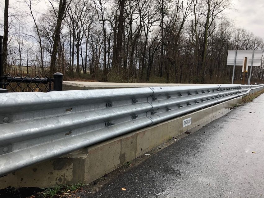
Temporary barrier can be either anchored or unanchored to the roadway. Anchored barrier deflects less
than unanchored barrier; however, it is more costly and typically requires intrusive anchors or pins to be
installed into the underlying pavement. In addition, crash-test performance is considerably better for the
vehicle and the occupant with unanchored barrier.
Temporary barriers are crash tested to the same Test Levels that were presented in Section 1.2 of this
manual. Based on their temporary nature, work zone devices are typically tested to withstand TL-3
prescribed forces. As such, it is MDOT SHA’s practice to consider Test Level 3 forces when accounting for
the deflection of temporary barrier into the work zone. Figure 4-2 captures the amount of buffer space
that MDOT SHA prefers behind barrier to the active work zone.
Deflection Space Provided behind Temporary
Roadway Surface Temporary Barrier Treatment
Barrier (ft)
Unanchored 5’ *
Portland Cement Concrete
Anchored 1’**
Unanchored 5’ *
Bituminous Concrete
Anchored 1.5’
Figure 4-2: Work Zone Buffer Space
* It should be noted that the 5’ buffer space prescribed for unanchored temporary barrier in Figure
4-2, is based upon the deflection of the non-proprietary pin and loop connection.
** 12” deflection behind the Portland Cement Concrete anchored temporary barrier is based on
MDOT SHA’s observation of historical performance.
The leading end of temporary barrier runs shall also be protected. In general, there are four ways to
protect temporary barrier end segments:
• Connect to an existing shielding system – This is MDOT SHA’s preferred practice when there is
permanent barrier in the vicinity of the temporary installation. A stiffness transition must be used
to connect the temporary barrier to permanent barrier installations. There have been several
systems developed and tested for MASH compliance that connect portable concrete barrier to W-
beam traffic barrier, reduced deflection portable concrete barrier, and permanent concrete
barrier.
• Overlap the temporary barrier behind a permanent shielding system – This method is not
preferred but is acceptable on a case by case basis. In this option, the temporary barrier system
is designed to overlap with a permanent installation. In these cases, the dynamic deflection and
the beginning length of need points of the permanent and temporary barrier system must be
considered when prescribing an overlap distance and offset.
• Install an appropriate End Treatment (Terminals, Crash Cushions) – Where there is no
permanent barrier in the vicinity or a connection cannot be made to a permanent system, a MASH
compliant end treatment can be prescribed from Maryland’s Qualified Products List.
• Flare outside the Clear Zone –The end treatment may be omitted in cases where the temporary
barrier can be flared an appropriate distance outside of the clear zone. Flare rates should be in
accordance with the current edition of the AASHTO Roadside Design Guide.
4-2: Temporary Barriers Last Modified: March 9, 2021Bridge Railing Manual
4.2 MDOT SHA Standard Low Deflection Applications
In addition to freestanding temporary barrier, The Maryland Department of Transportation – State
Highway Administration (MDOT SHA) Office of Structures currently maintains details of low deflection
temporary barrier applications. Below is a discussion of each MDOT SHA low deflection temporary barrier
detail.
Low Deflection Pinned to Asphalt (MOT-XXX)
This application is intended to be used on asphalt pavement surfaces and
Application Locations: adjacent to constrained work zones. The asphalt pavement must be at least 4” in
depth in order to function as intended.
MASH Test Level Approval: TL-3
The system consists of the following components:
• The barrier segments are 12’-6” long and have three anchors per barrier
segment.
• The temporary barrier segments are connected with a pin and loop
System Components: connection.
• The barrier segments are 24” wide.
• The system is anchored to the road with 48” long pins anchored at a 40°
angle relative to the road surface. This pin extends approximately 18”
behind the back toe of the barrier into the work zone.
The tested dynamic deflection was as follows:
• Permanent Set: 17.0”
System Deflection:
• Dynamic Deflection: 17.8”
• Working Width: 29.9”
MDOT SHA Required
18” measured from the back toe of the barrier.
Offset to Work Zone:
4-3: Temporary Barriers Last Modified: March 9, 2021Bridge Railing Manual
Low Deflection Pinned to Concrete Bridge Deck (MOT-101)
This application is intended to be used on concrete pavement surfaces or bridge
Application Locations:
decks adjacent to constrained work zones.
MASH Test Level Approval: TL-3 (Based on past performance for MDOT SHA. Crash testing is underway.)
The system consists of the following components:
• The barrier segments are 12’-0” long and have two anchors per barrier
segment.
• The temporary barrier segments are connected with a pin and loop
connection.
System Components:
• The single face barrier segments are 17” wide while the double face
barrier segments are 24” wide.
• An angle is welded to a plate which is fit around the toe of the barrier
and the road surface. A bolt is anchored into the barrier segment as well
as bolted through the road.
Unknown. This system is currently being evaluated and will subsequently be
System Deflection: crash tested. Based on past performance, it is assumed the system will deflect
12” during an impact.
MDOT SHA Required
12” measured from the back toe of the barrier.
Offset to Work Zone:
4-4: Temporary Barriers Last Modified: March 9, 2021You can also read