CAN-Gateway Configurator V6 - for CAN@net NT and CANbridge NT USER MANUAL - Ixxat
←
→
Page content transcription
If your browser does not render page correctly, please read the page content below
CAN-Gateway Configurator V6
         for CAN@net NT and CANbridge NT

                              USER MANUAL
                     4.02.0332.20001 1.6 en-US ENGLISH
Important User Information
Disclaimer
The information in this document is for informational purposes only. Please inform HMS Networks of any
inaccuracies or omissions found in this document. HMS Networks disclaims any responsibility or liability for any
errors that may appear in this document.

HMS Networks reserves the right to modify its products in line with its policy of continuous product development.
The information in this document shall therefore not be construed as a commitment on the part of HMS Networks
and is subject to change without notice. HMS Networks makes no commitment to update or keep current the
information in this document.

The data, examples and illustrations found in this document are included for illustrative purposes and are only
intended to help improve understanding of the functionality and handling of the product. In view of the wide range
of possible applications of the product, and because of the many variables and requirements associated with any
particular implementation, HMS Networks cannot assume responsibility or liability for actual use based on the data,
examples or illustrations included in this document nor for any damages incurred during installation of the product.
Those responsible for the use of the product must acquire sufficient knowledge in order to ensure that the product
is used correctly in their specific application and that the application meets all performance and safety requirements
including any applicable laws, regulations, codes and standards. Further, HMS Networks will under no circumstances
assume liability or responsibility for any problems that may arise as a result from the use of undocumented features
or functional side effects found outside the documented scope of the product. The effects caused by any direct or
indirect use of such aspects of the product are undefined and may include e.g. compatibility issues and stability
issues.

CAN-Gateway Configurator V6 User Manual                                                       4.02.0332.20001 1.6 en-US

Table of Contents                                                                                                                         Page

1    User Guide ........................................................................................................................... 5
     1.1      Related Documents ..........................................................................................................5
     1.2      Document History ............................................................................................................5
     1.3      Trademark Information .....................................................................................................5
     1.4      Conventions....................................................................................................................6

2    Product Description ............................................................................................................ 7
     2.1      Operational Modes CANbridge NT ......................................................................................7
              2.1.1       Repeater/Star Coupler ............................................................................................ 7
              2.1.2       Bridge................................................................................................................ 8
     2.2      Operational Modes CAN@net NT........................................................................................8
              2.2.1       ASCII Gateway Mode .............................................................................................. 8
              2.2.2       Local CAN Bridge Mode........................................................................................... 9
              2.2.3       CAN-Ethernet-CAN Bridge Mode ................................................................................ 9
              2.2.4       VCI Interface Mode.............................................................................................. 11
              2.2.5       ECI Interface Mode .............................................................................................. 11
     2.3      Add-Ons for Customer Specific Expansions ......................................................................... 11
              2.3.1       Lua ADK ........................................................................................................... 11
              2.3.2       C-API ixcan ........................................................................................................ 11

3    Installation......................................................................................................................... 12
     3.1      Installing the Software .................................................................................................... 12
     3.2      Checking and Updating the Device Firmware ...................................................................... 12
              3.2.1       Checking the Device Firmware ................................................................................ 12
              3.2.2       Updating the Device Firmware ................................................................................ 13

CAN-Gateway Configurator V6 User Manual                                                                            4.02.0332.20001 1.6 en-US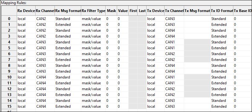
4 Connecting the Device in Use........................................................................................... 14
5 Configuring the Device...................................................................................................... 16
5.1 Basic Configuration Steps ................................................................................................ 16
5.1.1 CANbridge NT .................................................................................................... 16
5.1.2 CAN@net NT Interface Modes (ASCII, VCI, ECI)............................................................. 16
5.1.3 CAN@net NT Bridge Mode (Local CAN, CAN-Eth-CAN) .................................................... 17
5.1.4 Downloading the Configuration with Linux.................................................................. 18
5.2 General Settings ............................................................................................................ 19
5.2.1 Lua ADK ........................................................................................................... 19
5.2.2 Syslog .............................................................................................................. 20
5.2.3 MQTT .............................................................................................................. 20
5.2.4 Remote Access ................................................................................................... 20
5.2.5 Expert Mode...................................................................................................... 20
5.2.6 CAN Tunnel ....................................................................................................... 20
5.3 CAN Ports ..................................................................................................................... 22
5.3.1 Baud Rate Settings............................................................................................... 22
5.3.2 User Defined Baud Rates ....................................................................................... 24
5.3.3 Automatic Baud Rate Detection ............................................................................... 26
5.4 Communication Error Severity.......................................................................................... 27
5.5 Syslog Configuration ....................................................................................................... 28
5.5.1 Severity Level..................................................................................................... 28
5.5.2 Enabling the Syslog Configuration ............................................................................ 29
5.5.3 Defining Syslog Messages ...................................................................................... 29
5.6 MQTT Configuration ....................................................................................................... 30
5.6.1 Enabling the MQTT Configuration............................................................................. 31
5.6.2 Configuring MQTT/CAN Bridging .............................................................................. 32
5.6.3 Defining MQTT Messages ...................................................................................... 32
5.7 Action Rules .................................................................................................................. 34
5.7.1 Importing and Exporting Configurations ..................................................................... 34
5.7.2 Defining a Rule ................................................................................................... 34
5.7.3 Testing IF Events ................................................................................................. 39
5.7.4 Verify Configured Action Rules ................................................................................ 39
5.8 Mapping Table .............................................................................................................. 40
5.8.1 Configuration..................................................................................................... 41
5.8.2 Mask/Value Filter ................................................................................................ 42
5.8.3 Examples .......................................................................................................... 43
5.9 J1939 Mapping Table...................................................................................................... 44
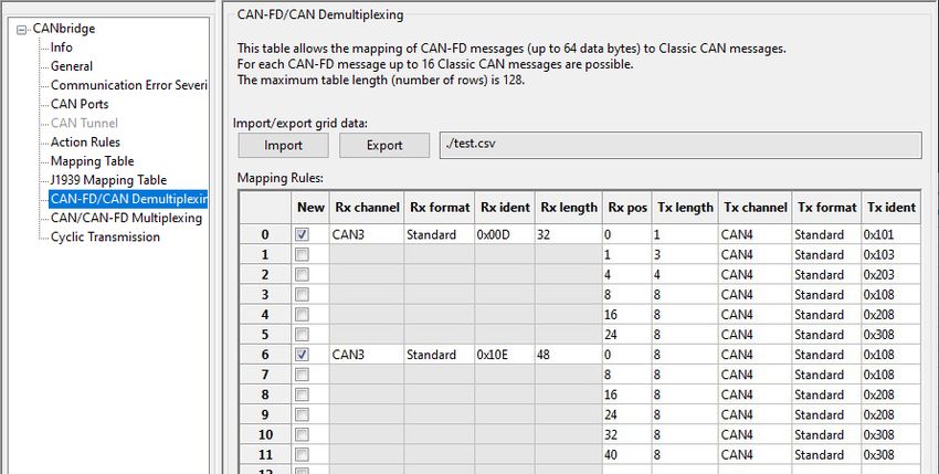
5.10 CAN FD/CAN Demultiplexing ............................................................................................ 46
5.11 CAN/CAN FD Multiplexing................................................................................................ 47
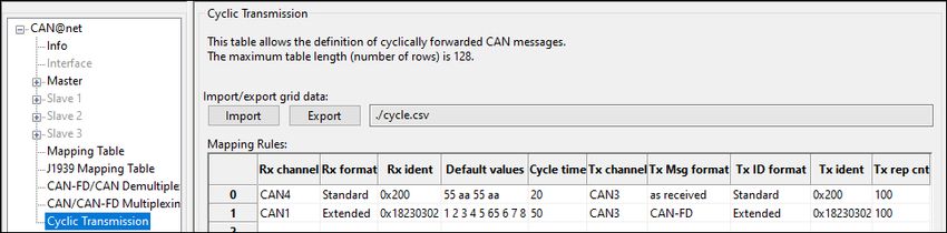
5.12 Cyclic Transmission......................................................................................................... 49
CAN-Gateway Configurator V6 User Manual 4.02.0332.20001 1.6 en-US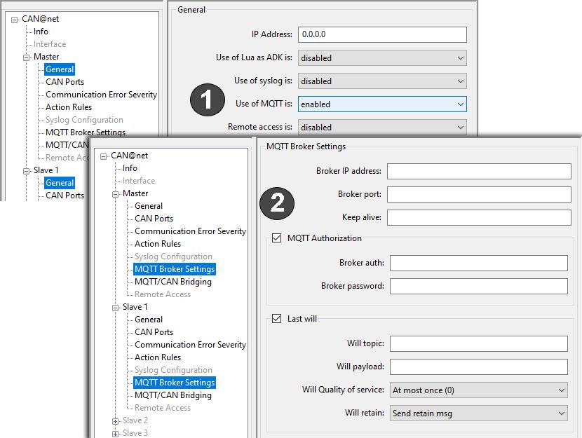
6    Dashboard ......................................................................................................................... 51

7    Command Line Program ................................................................................................... 52

8    Reset to Factory Settings .................................................................................................. 54

9    Security Settings................................................................................................................ 55

A    Lua License......................................................................................................................... 57

CAN-Gateway Configurator V6 User Manual                                                                        4.02.0332.20001 1.6 en-US

This page intentionally left blank
User Guide                                                                                                                   5 (58)

1              User Guide
               Please read the manual carefully. Make sure you fully understand the manual before using the
               product.

1.1            Related Documents
                Document                                                                                 Author
                User Manual CAN@net NT 100/200/420                                                       HMS
                User Manual CANbridge NT 200/420                                                         HMS
                Software Design Guide CAN@net NT 100/200/420 Generic Protocol for Gateway Mode           HMS
                User Manual CAN@net NT/CANbridge NT Lua ADK                                              HMS
                User Manual CAN@net NT C-API                                                             HMS

1.2            Document History
                Version    Date                    Description
                1.0        April 2018              First release
                1.1        June 2018               Minor corrections in chapter Action Rules
                1.2        January 2019            New CAN Gateway Configurator version, corrections and additional information in
                                                   chapters MQTT and J1939 mapping
                1.3        March 2019              Layout changes
                1.4        March 2020              Added service pack 2 functions
                1.5        December 2020           Adjusted links
                1.6        June 2021               Added UDP, mapping table changes (Tx Msg Format)

1.3            Trademark Information
               Ixxat® is a registered trademark of HMS Industrial Networks. All other trademarks mentioned in
               this document are the property of their respective holders.

CAN-Gateway Configurator V6 User Manual                                                                 4.02.0332.20001 1.6 en-US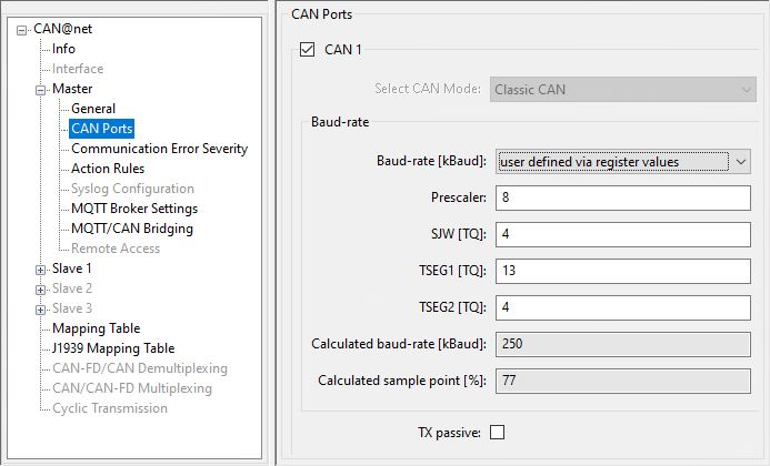
User Guide                                                                                                                   6 (58)

1.4            Conventions
               Instructions and results are structured as follows:
               ►     instruction 1
               ►     instruction 2
                     →     result 1
                     →     result 2
               Lists are structured as follows:
               •     item 1
               •     item 2
               Bold typeface indicates interactive parts such as connectors and switches on the hardware, or
               menus and buttons in a graphical user interface.
                This font is used to indicate program code and other
                kinds of data input/output such as configuration scripts.

               This is a cross-reference within this document: Conventions, p. 6
               This is an external link (URL): www.hms-networks.com

               Safety advice is structured as follows:

                             Cause of the hazard!
                             Consequences of not taking remediate action.
                             How to avoid the hazard.

               Safety signs and signalwords are used dependent on the level of the hazard.

                         This is additional information which may facilitate installation and/or operation.

                             This instruction must be followed to avoid a risk of reduced functionality and/or damage
                             to the equipment, or to avoid a network security risk.

                             Caution
                             This instruction must be followed to avoid a risk of personal injury.

                             WARNING
                             This instruction must be followed to avoid a risk of death or serious injury.

CAN-Gateway Configurator V6 User Manual                                                                   4.02.0332.20001 1.6 en-US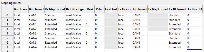
Product Description                                                                                                         7 (58)

2              Product Description
                        To use all features the latest version of the CAN-Gateway Configurator as well as the latest firmware of
                        the CAN NT device must be installed. For information about firmware versions below V6 contact Ixxat
                        support.

               With the CAN-Gateway Configurator the following products can be configured:
               •      CANbridge NT 200
               •      CANbridge NT 420
               •      CAN@net NT 100
               •      CAN@net NT 200
               •      CAN@net NT 420
               Depending on the device in use different operating modes and configuration options are possible.
               The different features are described in detail in the chapters of the respective feature in
               Configuring the Device, p. 16.

               For hardware information and how to connect the device observe the user manuals of the
               respective devices.

2.1            Operational Modes CANbridge NT
2.1.1          Repeater/Star Coupler
               The CANbridge NT 200 can be configured as Repeater and the CANbridge NT 420 as Star Coupler.
               In the Repeater/Star Coupler mode all messages are transmitted unchanged to the other ports in
               Classic CAN mode. Filters, CAN-ID modifications and CAN-FD mode are not possible.

               The following settings and features are possible:
               •      Expert mode
               •      Communication Error Severity
               •      Action Rules

CAN-Gateway Configurator V6 User Manual                                                                 4.02.0332.20001 1.6 en-US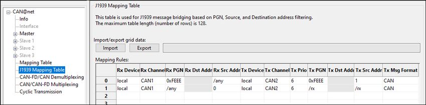
Product Description                                                                                            8 (58)

2.1.2          Bridge
               The Bridge mode allows free configuration of the transmission of CAN messages. With the
               CANbridge NT 420 NT bridging between Classic CAN and CAN FD is possible.

               The following settings and features are possible:
               •        Use of Lua ADK
               •        Expert mode
               •        Communication Error Severity
               •        Action Rules
               •        Mapping table
               •        J1939 Mapping
               •        CAN FD/CAN Demultiplexing (only CANbridge NT 420)
               •        CAN/CAN FD Multiplexing (only CANbridge NT 420)
               •        Cyclic transmission
               •        CAN tunnel to transmit messages between two Classic CAN networks via a CAN FD network
                        (only CANbridge NT 420)

2.2            Operational Modes CAN@net NT
2.2.1          ASCII Gateway Mode
               In the Gateway mode, the CAN@net NT is hooked to the local intranet or internet (firewall
               needed). This allows any TCP/UDP host within the reach of this intranet or internet to connect to
               the CAN@net NT and gain control of the CAN system. The Ethernet host can exchange
               commands and CAN messages using the ASCII protocol. The server relays the commands and
               messages to the CAN bus and vice versa.

                                              Host System                 CAN@net NT
                                                                            (Gateway)

                                                                                        1
                                                    1+2: CAN                            2
                                                    3+4: CAN or CAN-FD                  3
                                                                                        4

               Fig. 1       Gateway mode

               For information about the communication in Gateway mode and commands that are used to
               exchange CAN messages see Software Design Guide CAN@net NT 100/200/420 Generic Protocol
               for Gateway Mode on www.ixxat.com/support-bridges-gateways.

CAN-Gateway Configurator V6 User Manual                                                     4.02.0332.20001 1.6 en-US
Product Description 9 (58)
2.2.2 Local CAN Bridge Mode
A single device can be used as Local CAN Bridge, which allows to map individual messages from
and to each CAN port of the device. NT 420 devices additionally are capable of CAN FD.
The following settings and features are possible:
• Use of Lua ADK
• Syslog
• MQTT
• Remote access
• Expert mode
• Communication Error Severity
• Action Rules
• Mapping table
• J1939 Mapping
• CAN FD/CAN Demultiplexing (only CAN@net NT 420)
• CAN/CAN FD Multiplexing (only CAN@net NT 420)
• Cyclic transmission
2.2.3 CAN-Ethernet-CAN Bridge Mode
Exclusively one master device is allowed in the Bridge mode.
The CAN-Ethernet-CAN Bridge mode allows to connect CAN systems over an Ethernet TCP/IP
network, for example the local intranet or the internet (firewall needed). Minimum two devices
are required for a CAN-Ethernet-CAN Bridge. One has to be configured as master and one as
slave. With the NT 100 and NT 200 two devices can be combined to a CAN-Ethernet-CAN bridge.
With the NT 420 up to four devices can be combined. The CAN@net NT 420 additionally is
capable of CAN FD.
CAN@net NT CAN@net NT
(Master) (Slave)
1 1
2 2
CAN CAN
Fig. 2 CAN-Ethernet-CAN Bridge with 2 devices (NT 200)
CAN-Gateway Configurator V6 User Manual 4.02.0332.20001 1.6 en-USProduct Description 10 (58)
CAN@net NT CAN@net NT
(Master) (Slave)
1 1
2 2
3 3
Switch
4 4
CAN@net NT CAN@net NT
(Slave) (Slave)
1 1
2 2
3 3
4 4
1+2: CAN
3+4: CAN or CAN-FD
Fig. 3 CAN-Ethernet-CAN Bridge with 4 devices (NT 420)
The following settings and features are possible:
• Use of Lua ADK
• Syslog
• MQTT
• Remote access
• Expert mode
• Communication Error Severity
• Action Rules
• Mapping table
• J1939 Mapping
In the CAN-Ethernet-CAN Bridge mode each device can be configured differently. But to build a
Bridge configuration all devices must be configured in one configuration file. The configuration
has to be set completely for all devices (Master, Slave 1 to 3) and then the complete
configuration has to be downloaded to each device. In the Local CAN Bridge mode only one
device is connected and has to be configured.
Configuration fails, if the individual devices of a CAN-Ethernet-CAN Bridge are configured
from different configuration files! Observe that for the configuration of a CAN-Ethernet-
CAN Bridge each device must be configured with the same configuration file. If the
configuration is changed, the new configuration file has to be downloaded again to all
devices.
CAN-Gateway Configurator V6 User Manual 4.02.0332.20001 1.6 en-USProduct Description 11 (58)
2.2.4 VCI Interface Mode
The VCI interface mode is only possible via Ethernet.
With the VCI driver the CAN@net NT can be used as a PC interface with Windows. All VCI-based
Ixxat tools as well as customer-specific applications based on the VCI driver can be used. The VCI
driver offers the possibility to communicate with up to 128 CAN@net NT devices via LAN or
internet. The CAN@net NT 420 additionally is capable of CAN FD.
For information about the communication in the VCI mode and commands that are used to
exchange CAN messages see Software Design Guides in the VCI download package (available on
www.ixxat.com/driver-windows).
2.2.5 ECI Interface Mode
The ECI interface mode is only possible via Ethernet.
With the ECI driver the CAN@net NT can be used as a PC interface with Linux. All ECI-based Ixxat
tools as well as customer-specific applications based on the ECI driver can be used. The ECI driver
offers the possibility to communicate with up to 32 CAN@net NT devices via LAN or internet. The
CAN@net NT 420 additionally is capable of CAN FD.
For information about the communication in the ECI mode and commands that are used to
exchange CAN messages see Software Design Guides in the ECI download package (available on
the product support pages on www.ixxat.com/driver-linux).
2.3 Add-Ons for Customer Specific Expansions
2.3.1 Lua ADK
With the Lua Application Development Kit customer specific Lua scripts can be executed on the
CAN NT device in Bridge operational modes. By using the Lua ADK for handling and processing of
communication data the functionality of the standard application can be expanded.
For more information about the Lua ADK see User Manual CAN@net NT/CANbridge NT Lua ADK
on the product support pages on www.ixxat.com/support-bridges-gateways.
2.3.2 C-API ixcan
The CAN API for C uses the ASCII protocol interface to access the CAN@net NT. The C-API ixcan
converts the API calls into corresponding ASCII commands according to the ASCII Gateway Mode
of the CAN@net NT. With the application that uses the C-API ixcan the CAN@net NT can be
accessed exclusively or in shared access with a Bridge configuration.
For more information about the C-API ixcan see User Manual CAN@net NT C-API ixcan on
www.ixxat.com/support-bridges-gateways.
CAN-Gateway Configurator V6 User Manual 4.02.0332.20001 1.6 en-USInstallation 12 (58)
3 Installation
3.1 Installing the Software
To create a configuration for the CAN NT device, the CAN-Gateway Configurator running on a
Windows system and the Ixxat VCI driver are needed.
The VCI driver is constantly improved and expanded! Check if a newer version is available within the
product support pages on www.ixxat.com/support-bridges-gateways.
The CAN-Gateway Configurator and the device firmware are constantly improved and expanded! Check if
newer versions are available within the product support pages on
www.ixxat.com/support-bridges-gateways.
► Install the VCI driver on a Windows computer (see Installation Guide VCI Driver).
► Download the CAN-Gateway Configurator CANbridge NT & CAN@net NT 100/200/420
package from www.ixxat.com/support-bridges-gateways.
► Start the Ixxat CanGWconfig Setup.
→ Installation wizard starts automatically.
► Follow the instructions in installation program.
→ By default the CAN-Gateway Configurator is stored in C:\Program Files\HMS\Ixxat CAN-
Gateway Configurator V6.
→ The examples for (ASCII, LUA, C-API ixcan, and configuration) are stored in C:\Users
\Public\Documents\HMS\Ixxat CAN-Gateway Configurator\Examples.
► Check the firmware version in C:\Users\Public\Documents\HMS\Ixxat CAN-Gateway
Configurator\Examples\firmware and check if a newer firmware version is available on www.
ixxat.com/support-bridges-gateways
► If newer firmware version is available, update the firmware (see Updating the Device
Firmware, p. 13).
► In Windows Start menu open folder Ixxat CANGWconfig and start CAN-Gateway
Configurator V6.
3.2 Checking and Updating the Device Firmware
To use all features the latest firmware versions of the CAN-Gateway Configurator and of the
CAN@net NT/CANbridge NT device must be installed.
3.2.1 Checking the Device Firmware
► Make sure, that the latest VCI driver is installed.
► Make sure, that the device is correctly connected to the host computer and to power supply
(see User Manual of the respective device for more information).
► Make sure that the latest CAN-Gateway Configurator is installed (check within product
support pages on www.ixxat.com/support-bridges-gateways).
► Start the Ixxat CAN-Gateway Configurator.
► Open menu Scan and select All Ixxat devices.
→ Connected devices and firmware version of the devices are shown.
CAN-Gateway Configurator V6 User Manual 4.02.0332.20001 1.6 en-USInstallation 13 (58)
3.2.2 Updating the Device Firmware
Whether updating is permitted via Ethernet (CAN@net NT) or a password is needed, is
defined in the security settings (see Security Settings, p. 55). The default password is
IXXAT.
The firmware is constantly improved and expanded! Check if a newer firmware version is available
within the product support pages on www.ixxat.com/support-bridges-gateways.
With the CAN-Gateway Configurator devices with firmware version 5 and with version 6 can be
configured.
If the current firmware of the device in use is V4 or older:
► See update package on www.ixxat.com/support-bridges-gateways for information about
updating to V6 or contact Ixxat support.
If the current firmware of the device in use is V5 or V6:
► Check if newer firmware is available on www.ixxat.com/support-bridges-gateways.
► Download and unzip the update package.
► Make sure, that the device is connected to power supply.
► Connect the device to be updated to the computer.
► Make sure that the latest CAN-Gateway Configurator is installed (check within product
support pages on www.ixxat.com/support-bridges-gateways).
► Start the CAN-Gateway Configurator.
► In drop down list Select device type select the device in use.
► In drop down list Select device version select the current firmware version of the device V5
or V6.
The device is only found if the selected firmware version matches the firmware version of
the connected device.
► Scan for devices with button Scan and select the device in use in the combo box Target
Device.
► Click button Connect .
► Open menu Target and select Read configuration from target.
► Save the configuration on the computer.
► Open menu Target and select Update Firmware.
► Select the update file.
→ Firmware of the connected device is updated.
► In the status window check if the update is completed successfully.
► If the device was updated from V5 to V6 , select V6 in drop-down list Select device version.
► If using a V5 configuration, open menu File and select Convert V5 to V6 to convert the
configuration to the latest version.
► Write the saved configuration to the device.
HMS recommends to verify configurations that are converted from V5 to V6, to make sure that all
settings are working correctly.
CAN-Gateway Configurator V6 User Manual 4.02.0332.20001 1.6 en-USConnecting the Device in Use 14 (58)
4 Connecting the Device in Use
Connection disturbance possible if extension cable or longer cable is used!
HMS recommends connecting the interface directly with the included cable or via an
active USB hub to the computer according to the USB specification.
The different CAN@net NT types 100, 200 and 420 can not be combined. For CAN-
Ethernet-CAN Bridges use either NT 100 devices, NT 200 devices or NT 420 devices.
To use all features the latest firmware versions of the CAN-Gateway Configurator and the CAN NT device
must be installed.
1 2 3 4 5 6 7 8 9
Fig. 4 CAN-Gateway Configurator
► Make sure, that the latest driver and the latest CAN-Gateway Configurator is installed (see
Installing the Software, p. 12).
► Make sure, that the device is correctly connected to the host computer and to power supply
(see User Manual of the respective device for more information).
The CANbridge NT has to be connected via Mini USB cable. The CAN@net NT can be connected via Mini
USB cable, Ethernet or a router. HMS recommends to connect each device via Mini USB cable for the first
configuration of the device.
► Make sure, that the latest firmware is on the device (see Checking and Updating the Device
Firmware, p. 12).
► To start the Ixxat CAN-Gateway Configurator, in Windows Start menu open folder Ixxat
CANGWconfig and select CAN-Gateway Configurator V6.
► To identify the connected devices and the firmware version, open menu Scan (2) and select
All Ixxat devices.
→ Connected devices and firmware version of the devices are shown.
→ CAN@net NT devices that are connected via a router are not found. IP address and
device firmware must be known.
→ CAN@net NT devices with unknown or invalid IP address are not found, see User
Manual CAN@net NT 100/200/420, Scan for Devices with Unknown IP Address for
more information.
► Select the type of device in use in the drop-down list Select device type (1).
► Select the firmware version of the device in the drop-down list Select device version (3).
► Select the desired operational mode for the device in use in the drop-down list Select
operational mode (4) (for more information see Product Description, p. 7).
CAN-Gateway Configurator V6 User Manual 4.02.0332.20001 1.6 en-USConnecting the Device in Use 15 (58)
► In combo box Target Device (7) select the device in use.
or
If a CAN@net NT is connected via a router, enter the IP address in combo box Target Device
(7).
► Click button Connect (8) to connect the selected device.
If using the CAN@net NT:
► For ASCII Gateway, VCI Interface, and ECI Interface mode make sure, that the IP
address is in the range of the network in which the device integrated.
► For CAN-Ethernet-CAN bridge make sure, that the IP addresses of all devices of the
bridge are in the same IP range.
► For more information see User Manual CAN@net NT 100/200/420, Changing IP
Address and Device Name.
► To create a new project file, click button New (5).
or
To change the current configuration, click button Read from (9) and save the configuration.
► Configure the device in the selected mode (see Configuring the Device, p. 16).
CAN-Gateway Configurator V6 User Manual 4.02.0332.20001 1.6 en-USConfiguring the Device 16 (58)
5 Configuring the Device
In the configuration tree open Info to add information about the configuration in fields Author,
Configuration Name and Additional Info.
It is possible to create and save a configuration without a connected device. Saved configurations can be
downloaded to connected CAN NT devices with Windows and Linux by using the Command Line Tool (see
Downloading the Configuration with Linux, p. 18).
5.1 Basic Configuration Steps
5.1.1 CANbridge NT
► Make sure, that the device is connected and that the desired operational mode is selected
(see Connecting the Device in Use, p. 14).
► In the configuration tree select General and define the general settings (see General
Settings, p. 19).
► Configure the baud rate settings for all ports in use (see CAN Ports, p. 22).
► Configure the mapping table (see Mapping Table, p. 40).
Only messages that are entered in the mapping table are forwarded. By default, no filter
is set and all messages are rejected.
► Configure further settings if desired (see respective chapter Action Rules, J1939 Mapping,
Cyclic Transmission etc.).
► After the configuration click button Write to to write the configuration to the device.
► Click button Save or Save as to save the configuration.
5.1.2 CAN@net NT Interface Modes (ASCII, VCI, ECI)
The VCI interface mode and ECI interface mode can only be operated via Ethernet.
Configuration is possible via USB.
► Make sure, that the device is connected and that the desired operational mode is selected
(see Connecting the Device in Use, p. 14).
► In the configuration tree select Interface.
► If checkbox Only for specified device is enabled, enter the serial number of the device to
which the configuration can be written.
If ASCII Gateway Mode is selected:
► Configure the protocol line ending.
► Define the transport protocol (default TCP).
► If UDP is selected, make sure that UDP is also used on the client side.
► Define the IP port.
► If checkbox Expert Mode is enabled, select the desired settings (see Expert Mode, p.
20).
CAN-Gateway Configurator V6 User Manual 4.02.0332.20001 1.6 en-USConfiguring the Device 17 (58)
► After the configuration click button Write to to write the configuration to the device.
► Click button Save or Save as to save the configuration.
► To exchange messages in the Gateway mode, use ASCII commands (for more information
see Software Design Guide CAN@net NT 100/200/420 Generic Protocol for Gateway Mode).
► In the VCI interface mode configure the Device Server (for more information see Installation
Guide VCI Driver).
► For more information about the ECI interface mode, see ECI html help available in ECI
download package on product support pages onwww.ixxat.com/support-bridges-gateways.
5.1.3 CAN@net NT Bridge Mode (Local CAN, CAN-Eth-CAN)
In the CAN-Ethernet-CAN Bridge mode each device can be configured differently. But to build a Bridge
configuration all devices must be configured in one configuration file. The configuration has to be set
completely for all devices (Master, Slave 1 to 3) and then the complete configuration has to be
downloaded to each device. In the Local CAN Bridge mode only one device is connected and has to be
configured.
Exclusively one master device is allowed in the Bridge mode.
► Make sure, that the Master device is connected and that the desired operational mode is
selected (see Connecting the Device in Use, p. 14).
► Configure the following for the Master and for each Slave in use:
► In the configuration tree select General and enter the IP address of the device for CAN-
Ethernet-CAN bridges.
► Define the general settings (see General Settings, p. 19).
► In the configuration tree select CAN Ports and configure the baud rate settings for all
ports in use (see CAN Ports, p. 22).
► Configure further settings if desired (see respective chapter MQTT, Syslog, Action
Rules, etc.).
► Configure the mapping table (see Mapping Table, p. 40).
Only messages that are entered in the mapping table are forwarded. By default, no filter
is set and all messages are rejected.
► After the configuration click button Write to to write the configuration to the device.
► Click button Save or Save as to save the configuration.
► For the CAN-Ethernet-CAN Bridge connect the devices one after another and download the
configuration to each device.
► Observe that for the configuration of a CAN-Ethernet-CAN Bridge each device must be
configured with the same configuration file. If the configuration is changed, the new
configuration file has to be downloaded again to all devices.
CAN-Gateway Configurator V6 User Manual 4.02.0332.20001 1.6 en-USConfiguring the Device 18 (58)
5.1.4 Downloading the Configuration with Linux
The basic configurations, like the selection of the operating mode, can only be created with the
CAN-Gateway Configurator with Windows. A configuration can be created and saved without a
connected device and can then be downloaded to connected CAN NT devices with Linux by using
the Command Line Tool that is included in the scope of delivery.
► To be able to read and write configurations on CAN NT devices, copy the included file 60-bgi.
rules to the folder /etc/udev/rules.d/ (root access required).
► To activate the new rules, execute the following command:
udevadm control - -reload-rules
► To download a saved configuration file to CAN NT devices, start the command line tool
cangwfile without parameters.
→ Output shows the syntax, examples and all possible commands.
► Write the configuration to the target device (see Command Line Program, p. 52 for more
information about the Command Line Tool).
CAN-Gateway Configurator V6 User Manual 4.02.0332.20001 1.6 en-USConfiguring the Device 19 (58)
5.2 General Settings
Fig. 5 General settings
In the configuration tree in General the following settings can be enabled depending on the
device in use and the selected operational mode.
Setting Device Operational Mode
Lua ADK CAN@net NT 100/200/420 Local CAN Bridge, CAN-Eth-CAN Bridge
CANbridge NT 200/420 Bridge
Syslog CAN@net NT 100/200/420 Local CAN Bridge, CAN-Eth-CAN Bridge
MQTT CAN@net NT 100/200/420 Local CAN Bridge, CAN-Eth-CAN Bridge
Remote access CAN@net NT 100/200/420 Local CAN Bridge, CAN-Eth-CAN Bridge
Expert Mode CAN@net NT 100/200/420 Local CAN Bridge, CAN-Eth-CAN Bridge, ASCII
Gateway
CANbridge NT 200/420 Repeater/Star Coupler, Bridge
CAN tunnel CANbridge NT 420 Bridge
In the CAN-Ethernet-CAN Bridge mode the settings can be enabled for each connected Master
and Slave individually.
5.2.1 Lua ADK
The Ixxat Lua ADK is a firmware extension that is layered over the standard firmware and based
on the standard Lua 5.3.5 distribution. By using the Lua ADK for handling and processing of
communication data the functionality of the standard application can be expanded. Lua is a
powerful, lightweight scripting language for use within the application.
The Lua ADK supports two operational modes:
• running the Lua script on the target device in autonomous mode (Use of Lua ADK set to
enabled in target mode)
• running the Lua script on the host PC for debugging purposes, communicating with the
target device via USB (Use of Lua ADK set to enabled in remote mode)
For information about the Ixxat Lua ADK see User Manual CAN@net NT/CANbridge NT Lua ADK
on the product support pages on www.ixxat.com/support-bridges-gateways.
CAN-Gateway Configurator V6 User Manual 4.02.0332.20001 1.6 en-USConfiguring the Device 20 (58)
5.2.2 Syslog
If the use of syslog is set to enabled, the Syslog configuration is activated. For information how
to configure Syslog see Syslog Configuration, p. 28.
5.2.3 MQTT
If the use of MQTT is set to enabled, the configuration for MQTT Broker settings and MQTT/CAN
Bridging is activated. For information how to configure MQTT see MQTT Configuration, p. 30.
5.2.4 Remote Access
If Remote access is enabled, a device that is used in Bridge mode can be accessed in ASCII
Gateway mode simultaneously. The CAN controller must be configured and started by the Bridge
mode configuration in the CAN-Gateway Configurator.
The CAN controller is controlled via the Bridge and all ASCII commands related to the control are
blocked, this means the CAN controller cannot be stopped or modified via ASCII commands.
Cyclic messages cannot be defined via ASCII commands in remote access. CAN messages can be
sent and received via the ASCII protocol. To receive CAN messages on the host side via ASCII
commands, the messages must be added in the Mapping table of the Bridge configuration. The
ASCII device commands can also be used in Remote access.
For more information about the ASCII Interface mode and the commands see
CAN@net NT 100/200/420 Generic Protocol for Gateway Mode.
► If Remote access is enabled, open Remote Access in the configuration tree and configure
the Protocol line ending, the IP port, and the transport protocol if needed.
5.2.5 Expert Mode
If the checkbox Expert Mode is activated, the configuration of the master TCP connection can be
optimized for different use cases and the behavior in case of CAN message loss can be
configured.
Possible configuration optimizations for TCP/IP with CAN@net NT:
• for maximum throughput (default)
• for minimized latency
• for internet connections
• for slow internet connections
Possible behavior in case of CAN message loss:
• discard new messages (default)
• discard old messages
In the CAN-Ethernet-CAN Bridge mode the Expert mode of the Master can be configured
individually for the connection to each connected Slave.
5.2.6 CAN Tunnel
With two CANbridge NT 420 it is possible to transmit messages between two Classic CAN
networks via a CAN FD network (CAN tunnel). Only two identifiers are necessary for the CAN FD
network. Via these two CAN FD messages all Classic CAN messages are transferred. The busload
on the tunnel can be reduced due to the usage of the maximum length of 64 bytes. The Tx
message identifier of the CAN FD tunnel port of the first device must be configured to the Rx
message identifier of the CAN FD tunnel port of the second device and vice versa.
CAN-Gateway Configurator V6 User Manual 4.02.0332.20001 1.6 en-USConfiguring the Device 21 (58)
If hexadecimal values are used, they must begin with 0x.
Example: 0x55
► To activate a CAN tunnel via CAN FD between two devices, in the configuration tree select
General and select enabled in the field Use of CAN tunnel.
→ CAN Tunnel is enabled in the configuration tree.
► In the configuration tree select CAN Tunnel.
Fig. 6 CAN tunnel settings
► In drop-down list Tunnel Port select the transmitting port for the CAN FD messages.
► In drop-down list Classic Port select the transmitting port for the Classic CAN messages.
→ Classic CAN messages from the Classic Port are collected and transmitted as CAN FD
messages from the Tunnel Port to the second device.
► In field Tx message identifier enter the identifier of the CAN FD message to be transmitted
in decimal or hexadecimal values.
► In field Rx message identifier enter the identifier of the received CAN FD message in
decimal or hexadecimal values.
► In field timeout specify the maximum time until the CAN FD message is transmitted (even if
the 64 bytes are not filled yet).
► In Mapping Table configure the Classic CAN messages to be transmitted from the defined
Classic Port to the defined Tunnel port.
► Select tunnel in column Tx Channel and define the Classic CAN messages.
► Configure the CAN tunnel of the second device.
► In drop-down list Tunnel Port select the receiving port for CAN FD messages.
► In drop-down list Classic Port select the receiving port for the Classic CAN messages.
→ CAN FD messages that are received on the tunnel port are divided and transmitted as
Classic CAN messages to the configured Classic port.
► Make sure, that Tx message identifier of the first device matches Rx message identifier of
the second device.
► Make sure, that Rx message identifier of the first device matches Tx message identifier of
the second device.
CAN-Gateway Configurator V6 User Manual 4.02.0332.20001 1.6 en-USConfiguring the Device 22 (58)
5.3 CAN Ports
With the CAN@net NT in the CAN-Ethernet-CAN Bridge mode each device can be configured differently.
But to build a Bridge configuration all devices must be configured in one configuration file. The
configuration has to be set completely for all devices (Master, Slave 1 to 3) and then the complete
configuration has to be downloaded to each device.
5.3.1 Baud Rate Settings
With the CANbridge NT in Repeater/Star Coupler mode observe the bus load when
setting the baud rates. If the bus load is high on a port with high baud rate but the other
port has a low baud rate, a bus overload can occur.
Fig. 7 CAN settings NT 420
► With CAN@net NT configure the Master and each Slave that is active (black) in the
configuration tree.
► Select CAN Ports in the configuration tree (1).
→ Form to set baud rate of each port of the selected device appears on the right side.
► If only certain CAN ports of a device are used, deactivate the check boxes of the CAN ports
(2) not to be used.
→ Setting possibilities of deactivated CAN port are disabled.
Baud Rate (3)
► Configure the baud rate for each active CAN port in drop-down list (3).
► With product variants 420 observe the different CAN-FD settings for CAN ports 3 and 4 (see
CAN Mode (5), p. 23).
Setting the baud rate is possible in different ways:
• predefined CiA baud rate (listed in drop-down list)
CAN-Gateway Configurator V6 User Manual 4.02.0332.20001 1.6 en-USConfiguring the Device 23 (58)
• setting with bit timing register (see User Defined Baud Rates, p. 24)
• automatic baud rate detection (see Automatic Baud Rate Detection, p. 26)
TX Passive Mode (4)
If a CAN port is in TX passive mode, it acts exclusively as listener. It receives messages, but does
not transmit messages, nor affect the communication (neither acknowledge bit nor error frames
are generated).
► To set a port to TX passive mode, activate the check box TX passive mode (3).
CAN Mode (5)
The NT 420 supports CAN FD. CAN 1 and CAN 2 are Classic CAN channels.
For CAN 3 and CAN 4 the following CAN modes can be selected:
• Classic CAN
• ISO CAN FD
• Non-ISO CAN FD
CAN FD does not support automatic baud rate detection.
► Select the CAN mode in drop-down list Select CAN Mode (5).
► In CAN FD mode configure the baud rate for Arbitration Phase (6) and the baud rate for
Data Phase (7).
Arbitration Phase and Data Phase
CAN FD uses two baud rates: one for the arbitration phase, which is limited to the maximum of
Classic CAN (1000 kBit/s) and one for the data phase (up to 10 MBit/s).
CAN-Gateway Configurator V6 User Manual 4.02.0332.20001 1.6 en-USConfiguring the Device 24 (58)
5.3.2 User Defined Baud Rates
HMS Industrial Networks recommends using the predefined standard baud rates. If user defined baud
rates are used make sure, that the entered values are valid.
If the baud rate is set with the bit timing register of the controller, baud rates that are not
defined by CiA can be used.
The clock frequency of the CAN module applied for the calculation of the baud rate is 36 MHz
resp. 80 MHz.
Formula for the calculation of the baud rate:
CAN 1 and CAN 2 (Classic CAN)
• baud rate [kBaud] = 36 000 / ((TSEG1 + TSEG2 +1) * Prescaler)
CAN 3 and CAN 4 (Classic CAN/CAN FD)
• baud rate [kBaud] = 80 000 / ((TSEG1 + TSEG2 +1) * Prescaler)
► For user defined baud rates select user defined via register values.
► Set the values for Prescaler, SJW, TSEG1 and TSEG2.
Fig. 8 Bit timing register
CAN-Gateway Configurator V6 User Manual 4.02.0332.20001 1.6 en-USConfiguring the Device 25 (58)
Calculator for Baud Rate Register Values
With the integrated calculator all necessary register values for a desired baud rate can be
calculated.
Observe that the CAN ports have different controllers and therefore different register
values. Make sure, the correct CAN port is selected in the calculator.
► To open the calculator click button Calculator in the toolbar.
→ Calculator is opened.
► In the drop-down list CAN port select the CAN port the user defined register values are used
for.
► Enter the desired baud-rate in field Baud-rate.
► Enter the desired sample point ratio in percent in field Sample-point ratio.
► Click button Calc.
→ Possibilities of values to achieve the desired baud rate and sample point are listed.
Setting Recommendations for CAN FD
HMS Industrial Networks recommends using the same bit timing settings in all connected nodes.
Observe the following recommendations:
• Set arbitration and data phase prescaler as low as possible.
• Configure the same arbitration sample point for all CAN nodes.
• Configure the same data phase primary sample point for all CAN nodes.
• Set SJW for arbitration phase as large as possible.
• Set SJW for data phase as large as required by used oscillator (clock source).
CAN-Gateway Configurator V6 User Manual 4.02.0332.20001 1.6 en-USConfiguring the Device 26 (58)
5.3.3 Automatic Baud Rate Detection
Automatic baud rate detection is exclusively possible if at least two nodes per bus are
active.
Automatic baud rate detection is exclusively possible with Classic CAN.
The ports with activated automatic baud rate detection remain in automatic baud rate detection
until the baud rate is detected on each port. Other ports with set or already detected baud rate
work regardless of the ports that remain in automatic baud rate detection.
During the automatic baud rate detection CAN 1 LED, CAN 2/3/4 LED (depending on where
automatic baud rate detection is enabled) and Status LED indicate the status.
Status CAN 1 LED CAN 2 LED Status LED
Automatic baud rate detection active on Orange flashing Orange flashing Green and orange
both channels flashing
Baud rate detected on CAN 1, baud rate Off Orange flashing Green and orange
detection on CAN 2 active flashing
Baud rate on CAN 2 detected or adopted Green flashing Green flashing Green flashing
from CAN 1, communication present
Adopting a Detected Baud Rate to Further CAN Ports
With Actions Rules it is possible to configure to adopt a detected baud rate of a CAN port to a
second CAN port. The baud rate is only adopted, if no baud rate is set or detected on the second
port.
► In drop-down list Baud-rate (3) select automatic baud-rate detection for the individual
ports.
► In the configuration tree select Action Rules.
► Click in column IF Event and select event type CAN baud-rate detected.
► Select the port and click button OK.
→ IF event is entered in the table.
► Click in column THEN action and select action type take over CAN baud-rate.
► Select the port on which the detected baud rate is adopted and click button OK.
→ THEN-action is entered in the table.
► For information about further configuration possibilities see Action Rules, p. 34.
CAN-Gateway Configurator V6 User Manual 4.02.0332.20001 1.6 en-USConfiguring the Device 27 (58)
5.4 Communication Error Severity
With the CAN@net NT in the CAN-Ethernet-CAN Bridge mode each device can be configured differently.
But to build a Bridge configuration all devices must be configured in one configuration file. The
configuration has to be set completely for all devices (Master, Slave 1 to 3) and then the complete
configuration has to be downloaded to each device.
Fig. 9 Communication Error Severity
The communication error state can be used as a condition for Action Rules in all autonomous
setups. With Actions Rules it is possible to define an event to take place if the device changes in
state warning or error. See Action Rules, p. 34 for more information.
• Start-up delay defines the delay until the monitoring is activated after the power on of the
device. (Exception: a bus off is directly handled.)
• CAN message lost defines which error state is set after an overload situation inside the
device, e.g. at a buffer overflow.
• CAN communication error defines which error state is set if a CAN controller goes into bus
off state for each CAN port separately.
• CAN communication timeout defines which error state is set if no message is received or
transmitted for over 10 seconds for each CAN port separately.
• Possible settings:
– no matter: no reaction
– warning: a Communication changed to warning event is generated
– error: a Communication changed to error event is generated
Observe for the configuration, that the device must be stopped and started to leave the states warning
and error.
CAN-Gateway Configurator V6 User Manual 4.02.0332.20001 1.6 en-USConfiguring the Device 28 (58)
5.5 Syslog Configuration
With the CAN@net NT in the CAN-Ethernet-CAN Bridge mode each device can be configured differently.
But to build a Bridge configuration all devices must be configured in one configuration file. The
configuration has to be set completely for all devices (Master, Slave 1 to 3) and then the complete
configuration has to be downloaded to each device.
Fig. 10 Syslog configuration
Syslog messages are only possible with the CAN@net NT via Ethernet.
If Syslog is enabled, standardized log messages can be transmitted to a receiver with a specified
IP address. In Action Rules it has to be defined which syslog messages are transmitted from the
CAN@net NT.
5.5.1 Severity Level
The severity levels are defined by the syslog standard. The severity level of the syslog messages
is set in action rules for each message individually. The severity level setting in the menu syslog
configuration works as a filter. All messages with the selected severity level and lower are
forwarded to the syslog server.
Example:
If severity level Error (3) is set, the messages with the following severity levels are forwarded to
the syslog server:
• Error (3)
• Critical (2)
• Alert (1)
• Emergency (0)
CAN-Gateway Configurator V6 User Manual 4.02.0332.20001 1.6 en-USConfiguring the Device 29 (58)
5.5.2 Enabling the Syslog Configuration
► To enable Syslog, in the configuration tree select General and select enabled in the field
Use of Syslog.
→ Syslog Configuration is enabled in the configuration tree.
► In the configuration tree select Syslog Configuration.
► Define the IP address of the syslog server.
DNS entries are possible with the latest CAN-Gateway Configurator version.
► Select the severity level filter in drop-down list Severity level.
5.5.3 Defining Syslog Messages
For each syslog message the following has to be defined via action rules:
• event (trigger) to transmit a syslog message
• severity level
• payload (ASCII string)
► Enable the syslog configuration (see Enabling the Syslog Configuration, p. 29).
► Define syslog messages via Action Rules:
► Configure an IF event to set the trigger for the transmission of a syslog message.
► As THEN action select the action type Send SYSLOG message and define the message.
► For more information see Action Rules, p. 34.
CAN-Gateway Configurator V6 User Manual 4.02.0332.20001 1.6 en-USConfiguring the Device 30 (58)
5.6 MQTT Configuration
With the CAN@net NT in the CAN-Ethernet-CAN Bridge mode each device can be configured differently.
But to build a Bridge configuration all devices must be configured in one configuration file. The
configuration has to be set completely for all devices (Master, Slave 1 to 3) and then the complete
configuration has to be downloaded to each device.
Fig. 11 MQTT configuration
MQTT messages are only possible with the CAN@net NT via Ethernet.
Fig. 12 MQTT Publisher and Subscriber
The CAN@net NT supports MQTT v3.1.1 and can act as publisher and as subscriber. With the
MQTT/CAN Bridging module CAN messages of a defined format can be published and received
via MQTT. Additionally as publisher the CAN@net NT can publish messages via MQTT that can be
individually defined in Action Rules. The MQTT broker has to be configured in MQTT Broker
Settings.
HMS recommends to use a MQTT broker within the local firewall. Observe that MQTT is a
open and unprotected protocol and that third parties can read the transmitted messages
if a public broker is used.
CAN-Gateway Configurator V6 User Manual 4.02.0332.20001 1.6 en-USConfiguring the Device 31 (58)
5.6.1 Enabling the MQTT Configuration
Enabling MQTT
► To enable MQTT, in the configuration tree select MQTT and select enabled in the field Use
of MQTT.
→ MQTT Broker Settings is enabled in the configuration tree.
► In the configuration tree select MQTT Broker Settings.
► Enter the IP address of the desired broker (within the local firewall) in Broker IP address.
DNS entries are possible with the latest CAN-Gateway Configurator version.
► Enter the broker port in Broker Port.
► Define the keep alive time in field Keep alive.
The keep alive functionality assures that the connection is open and both broker and client are
connected to one another. When no messages are transmitted and the keep alive time is
exceeded the subscribing client has to transmit a ping request to ensure that the connection is
still open.
MQTT Authorization
► If the broker in use demands an authorization, activate the checkbox MQTT Authorization
and enter the authorization and the password of the broker.
Last Will
The last will functionality is used to inform subscribing clients if a publishing client is
disconnected. The broker stores the last will message of the publishing client. If this client is
disconnected abruptly the broker transmits the message to all subscribing clients.
According to the MQTT specification the last will message is transmitted in the following cases:
• Server detected an I/O error or network failure.
• Client fails to communicate within keep alive time.
• Client closes the network connection without sending a DISCONNECT package.
• Server closes the network connection because of a protocol error.
► To define the last will, activate the checkbox Last will.
► Define the will topic and the will payload.
For topic and payload it is possible to use system variables that are replaced with actual values when a
message is sent (see System Variables for Topic and Payload, p. 33).
► Select the Quality of service for the last will message in drop-down list Will Quality of
service.
► Define if a retain message is transmitted in the drop-down list Will retain.
CAN-Gateway Configurator V6 User Manual 4.02.0332.20001 1.6 en-USConfiguring the Device 32 (58)
5.6.2 Configuring MQTT/CAN Bridging
With the MQTT/CAN Bridging module CAN messages in JSON format can be published and
received via MQTT.
► Enable the MQTT configuration (see Enabling the MQTT Configuration, p. 31).
► In the configuration tree select MQTT/CAN Bridging.
► To subscribe to a CAN message, enter the MQTT topic of the message in the table MQTT
Subscribe.
→ If an MQTT message of the defined format is published, it is received by the CAN@net
NT.
► To publish a received CAN message via MQTT, enter the message and the MQTT topic in the
table MQTT Publish.
For the topic it is possible to use system variables that are replaced with actual values when a message is
sent (see System Variables for Topic and Payload, p. 33).
Example: JSON Format of a CAN Message
{“port”:1, “format”:”csd”,”ident”:256,”data”:[17,34,51,68]}
port CAN port number (NT 100: 1, NT 200: 1...2, NT 420: 1...4)
format Message format according to CFT:
• C – Controller type (C – CAN, F — CAN FD)
• F – Frame Format (S – Standard, E – Extended)
• T – Frame Type (D – Data, R – RTR)
Remote frames (RTR) are only supported by Classic CAN.
ident Message identifier (decimal)
data List of data bytes (0..64 values)
5.6.3 Defining MQTT Messages
As publisher the CAN@net NT can publish messages via MQTT that can be individually defined in
Action Rules.
For each MQTT message the following has to be defined via Action Rules:
• event (trigger) to transmit an MQTT message
• message topic (string to filter and route the messages to the subscribers)
• message payload (ASCII string)
• Quality of Service (QoS)
If the Master and the Slave device use the same broker, the topics of the messages of Master and Slave
must be different (add e.g. the serial number).
► Enable the MQTT configuration (see Enabling the MQTT Configuration, p. 31.
► Define MQTT messages via Action Rules:
► Configure an IF event to set the trigger for the transmission of an MQTT message.
► As THEN action select the action type Send MQTT message and define the message.
► For information about the configuration possibilities see Action Rules, p. 34.
CAN-Gateway Configurator V6 User Manual 4.02.0332.20001 1.6 en-USYou can also read