DrillC mmand Personal User Guide - Great Plains Manufacturing
←
→
Page content transcription
If your browser does not render page correctly, please read the page content below
Great Plains

DrillC mmand
Personal User Guide

Step-by-step instructions for easy set-up and operation
                            Version 02.02.02.00 - 02.02.03.00

                                 Click Here

                                  Jump to interactive content

     Manual No. 160-502M | Published 2021-05-27 | Interactive Content available

User Guide Support

        Product Support
        We at Great Plains thank you for choosing DrillCommand to aid you in having a successful crop.
        If you have any problems with your software or do not understand any part of this manual,
        please discuss the matter with your dealership service manager first. If your dealer is unable to
        resolve the problem or the issue is parts related, please contact:

                                         Great Plains Service Department
                                                 1525 E. North St.
                                                  P.O. Box 5060
                                              Salina, KS 67402-5060

        Or go to www.greatplainsag.com and follow the contact information at the bottom of your
        screen for our service department.

        Supported Languages
        DrillCommand has language support for the following languages:

                   German                                            Russian
                   French                                            Polish
                   Ukranian                                          Spanish
                   Danish                                            Finnish
                   Czech                                             Swedish
                   Hungarian                                         Estonian
                   Bulgarian                                         Lithuanian
                   Romanian                                          Latvian
        Supported Measurements
        DrillCommand also has support for the following units of measurement: metric, U.S. customary,
        and imperial.
        Language and measurement controls are accessed through your terminal. See your terminal
        manual for more information.

DrillCommand | Version 02.02.04.00 - 02.03.05.00 | 2021-05-27                                          3
User Guide Support

        Copyright © 2021

        All rights reserved. No part of this publication may be reproduced, distributed, or transmitted in
        any form or by any means, including photocopying, recording, or other electronic or
        mechanical methods, without the prior written permission of the publisher, except in the case
        of brief quotations embodied in critical reviews and certain other noncommercial uses
        permitted by copyright law.
        DrillCommand is a trademark of Great Plains Manufacturing, Inc. Brand and product names that
        appear and are owned by others are trademarks of their respective owners.
        For permission requests, write to the publisher at the address below.

        Great Plains Mfg.
        1525 E. North St.
        P.O. Box 5060
        Salina, KS 67402

        You can also visit our website at www.greatplainsag.com/en/manuals/905/product-manuals
        for a full catalog of this and other manuals.

        Ordering Information:
        Quantity sales. Special discounts are available on quantity purchases by corporations,
        associations, and others. For details, contact the publisher at the address above.
        Orders for personal, non-commercial use. Please contact our service department by mail or our
        website www.greatplainsag.com.

        Printed in the United States of America

DrillCommand | Version 02.02.04.00 - 02.03.05.00 | 2021-05-27                                           4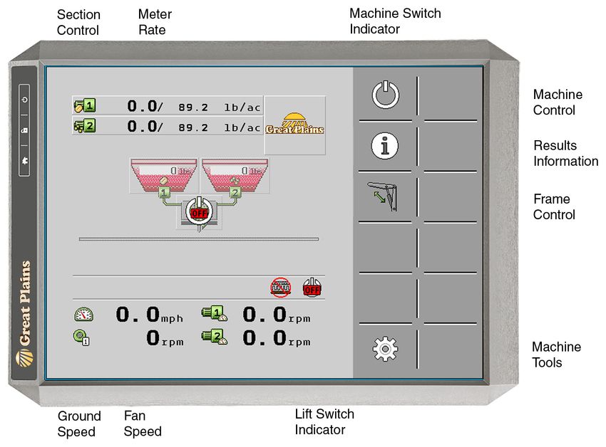
1 DrillCommand at a Glance . . . . . . . . . . . . . . . . . . . . . . . . . . . . . . . . . . . . . . . . . . . . . . . . . . . . . . . . . . . . . . . 7
      1.1 Overview of This Guide. . . . . . . . . . . . . . . . . . . . . . . . . . . . . . . . . . . . . . . . . . . . . . . . . . . . . . . . . . . . . . . . . . . . 7
            1.1.1 Software Version. . . . . . . . . . . . . . . . . . . . . . . . . . . . . . . . . . . . . . . . . . . . . . . . . . . . . . . . . . . . . . . . . . . . 7
            1.1.2 Maintenance . . . . . . . . . . . . . . . . . . . . . . . . . . . . . . . . . . . . . . . . . . . . . . . . . . . . . . . . . . . . . . . . . . . . . . . . 7
            1.1.3 Display Screen . . . . . . . . . . . . . . . . . . . . . . . . . . . . . . . . . . . . . . . . . . . . . . . . . . . . . . . . . . . . . . . . . . . . . . 8
                  Power . . . . . . . . . . . . . . . . . . . . . . . . . . . . . . . . . . . . . . . . . . . . . . . . . . . . . . . . . . . . . . . . . . . . . . . . . . . . . . . 8
                  Navigation . . . . . . . . . . . . . . . . . . . . . . . . . . . . . . . . . . . . . . . . . . . . . . . . . . . . . . . . . . . . . . . . . . . . . . . . . . . 8
                  Making Changes . . . . . . . . . . . . . . . . . . . . . . . . . . . . . . . . . . . . . . . . . . . . . . . . . . . . . . . . . . . . . . . . . . . . . 8

2 Quick Start Guide . . . . . . . . . . . . . . . . . . . . . . . . . . . . . . . . . . . . . . . . . . . . . . . . . . . . . . . . . . . . . . . . . . . . . . . . . . 9
      2.1 Initial Start Up and Navigation . . . . . . . . . . . . . . . . . . . . . . . . . . . . . . . . . . . . . . . . . . . . . . . . . . . . . . . . . . . . 9
             2.1.1 Home, Setting, and Calibration Screen . . . . . . . . . . . . . . . . . . . . . . . . . . . . . . . . . . . . . . . . . . . . . 9
             2.1.2 Calibrate Speed . . . . . . . . . . . . . . . . . . . . . . . . . . . . . . . . . . . . . . . . . . . . . . . . . . . . . . . . . . . . . . . . . . . . 10
            2.1.3      Tramlines . . . . . . . . . . . . . . . . . . . . . . . . . . . . . . . . . . . . . . . . . . . . . . . . . . . . . . . . . . . . . . . . . . . . . . . . .    11
            2.1.4      Hoppers. . . . . . . . . . . . . . . . . . . . . . . . . . . . . . . . . . . . . . . . . . . . . . . . . . . . . . . . . . . . . . . . . . . . . . . . . . .   11
            2.1.5      Add a Product. . . . . . . . . . . . . . . . . . . . . . . . . . . . . . . . . . . . . . . . . . . . . . . . . . . . . . . . . . . . . . . . . . . . .         12
            2.1.6      Metering . . . . . . . . . . . . . . . . . . . . . . . . . . . . . . . . . . . . . . . . . . . . . . . . . . . . . . . . . . . . . . . . . . . . . . . . . .   13
            2.1.7      Running DrillCommand . . . . . . . . . . . . . . . . . . . . . . . . . . . . . . . . . . . . . . . . . . . . . . . . . . . . . . . . . . .                     15

3 Terminal Operation and Configuration . . . . . . . . . . . . . . . . . . . . . . . . . . . . . . . . . . . . . . . . . . . . . 17
      3.1 Home Screen Menu . . . . . . . . . . . . . . . . . . . . . . . . . . . . . . . . . . . . . . . . . . . . . . . . . . . . . . . . . . . . . . . . . . . . . . 18
              Informational Icons. . . . . . . . . . . . . . . . . . . . . . . . . . . . . . . . . . . . . . . . . . . . . . . . . . . . . . . . . . . . . . . . . . 19
              Home Screen Controls. . . . . . . . . . . . . . . . . . . . . . . . . . . . . . . . . . . . . . . . . . . . . . . . . . . . . . . . . . . . . . . 19
              Tramline Bout . . . . . . . . . . . . . . . . . . . . . . . . . . . . . . . . . . . . . . . . . . . . . . . . . . . . . . . . . . . . . . . . . . . . . . . 20
              Machine Control . . . . . . . . . . . . . . . . . . . . . . . . . . . . . . . . . . . . . . . . . . . . . . . . . . . . . . . . . . . . . . . . . . . . 21
             3.1.1 Results Information . . . . . . . . . . . . . . . . . . . . . . . . . . . . . . . . . . . . . . . . . . . . . . . . . . . . . . . . . . . . . . . . 22
                   Meter Counters . . . . . . . . . . . . . . . . . . . . . . . . . . . . . . . . . . . . . . . . . . . . . . . . . . . . . . . . . . . . . . . . . . . . . 23
                   Total Results Screen . . . . . . . . . . . . . . . . . . . . . . . . . . . . . . . . . . . . . . . . . . . . . . . . . . . . . . . . . . . . . . . . . 23
          3.1.2 Blockage Sensor View. . . . . . . . . . . . . . . . . . . . . . . . . . . . . . . . . . . . . . . . . . . . . . . . . . . . . . . . . . . . . . 24
      3.2 Machine Settings Menu . . . . . . . . . . . . . . . . . . . . . . . . . . . . . . . . . . . . . . . . . . . . . . . . . . . . . . . . . . . . . . . . . 26
                Sub Menus. . . . . . . . . . . . . . . . . . . . . . . . . . . . . . . . . . . . . . . . . . . . . . . . . . . . . . . . . . . . . . . . . . . . . . . . . . 27
             3.2.1 Tramline Settings . . . . . . . . . . . . . . . . . . . . . . . . . . . . . . . . . . . . . . . . . . . . . . . . . . . . . . . . . . . . . . . . . . 28
                   Installing Tramline Equipment . . . . . . . . . . . . . . . . . . . . . . . . . . . . . . . . . . . . . . . . . . . . . . . . . . . . . . . 29
                   Tramline Settings . . . . . . . . . . . . . . . . . . . . . . . . . . . . . . . . . . . . . . . . . . . . . . . . . . . . . . . . . . . . . . . . . . . 29
                   Sensor Settings . . . . . . . . . . . . . . . . . . . . . . . . . . . . . . . . . . . . . . . . . . . . . . . . . . . . . . . . . . . . . . . . . . . . . 29
                   Preset Rhythm Settings. . . . . . . . . . . . . . . . . . . . . . . . . . . . . . . . . . . . . . . . . . . . . . . . . . . . . . . . . . . . . . 29
                   Custom Rhythm Settings . . . . . . . . . . . . . . . . . . . . . . . . . . . . . . . . . . . . . . . . . . . . . . . . . . . . . . . . . . . . 29
             3.2.2 Hopper Settings . . . . . . . . . . . . . . . . . . . . . . . . . . . . . . . . . . . . . . . . . . . . . . . . . . . . . . . . . . . . . . . . . . . 32
                   Settings Adjustments . . . . . . . . . . . . . . . . . . . . . . . . . . . . . . . . . . . . . . . . . . . . . . . . . . . . . . . . . . . . . . . 33
                   Hopper Display . . . . . . . . . . . . . . . . . . . . . . . . . . . . . . . . . . . . . . . . . . . . . . . . . . . . . . . . . . . . . . . . . . . . . 33
             3.2.3 Metering Settings . . . . . . . . . . . . . . . . . . . . . . . . . . . . . . . . . . . . . . . . . . . . . . . . . . . . . . . . . . . . . . . . . . 34
                   Adjustable Meter Settings . . . . . . . . . . . . . . . . . . . . . . . . . . . . . . . . . . . . . . . . . . . . . . . . . . . . . . . . . . . 35
             3.2.4 Weigh System Settings . . . . . . . . . . . . . . . . . . . . . . . . . . . . . . . . . . . . . . . . . . . . . . . . . . . . . . . . . . . . 38
                   Information and Settings . . . . . . . . . . . . . . . . . . . . . . . . . . . . . . . . . . . . . . . . . . . . . . . . . . . . . . . . . . . . 39

DrillCommand | Version 02.02.04.00 - 02.03.05.00 | 2021-05-27                                                                                                                          5
3.2.5 Blockage System Settings. . . . . . . . . . . . . . . . . . . . . . . . . . . . . . . . . . . . . . . . . . . . . . . . . . . . . . . . . . 40
                Sensitivity Setting . . . . . . . . . . . . . . . . . . . . . . . . . . . . . . . . . . . . . . . . . . . . . . . . . . . . . . . . . . . . . . . . . . . 41
        3.2.6 Speed Settings . . . . . . . . . . . . . . . . . . . . . . . . . . . . . . . . . . . . . . . . . . . . . . . . . . . . . . . . . . . . . . . . . . . . . 42
              Adjustable Speed Settings. . . . . . . . . . . . . . . . . . . . . . . . . . . . . . . . . . . . . . . . . . . . . . . . . . . . . . . . . . . 43
              Calibrate Speed . . . . . . . . . . . . . . . . . . . . . . . . . . . . . . . . . . . . . . . . . . . . . . . . . . . . . . . . . . . . . . . . . . . . . 44
    3.3 Machine Configuration Menu . . . . . . . . . . . . . . . . . . . . . . . . . . . . . . . . . . . . . . . . . . . . . . . . . . . . . . . . . . . 46
              Sub Menus. . . . . . . . . . . . . . . . . . . . . . . . . . . . . . . . . . . . . . . . . . . . . . . . . . . . . . . . . . . . . . . . . . . . . . . . . . 47
          3.3.1 Implement Configuration. . . . . . . . . . . . . . . . . . . . . . . . . . . . . . . . . . . . . . . . . . . . . . . . . . . . . . . . . . 48
                Adjustable Implement Settings . . . . . . . . . . . . . . . . . . . . . . . . . . . . . . . . . . . . . . . . . . . . . . . . . . . . . . 49
          3.3.2 Hopper Configuration . . . . . . . . . . . . . . . . . . . . . . . . . . . . . . . . . . . . . . . . . . . . . . . . . . . . . . . . . . . . . 52
                Hopper Configuration Display . . . . . . . . . . . . . . . . . . . . . . . . . . . . . . . . . . . . . . . . . . . . . . . . . . . . . . . 53
                Virtual Hopper . . . . . . . . . . . . . . . . . . . . . . . . . . . . . . . . . . . . . . . . . . . . . . . . . . . . . . . . . . . . . . . . . . . . . . 53
          3.3.3 Product Configuration . . . . . . . . . . . . . . . . . . . . . . . . . . . . . . . . . . . . . . . . . . . . . . . . . . . . . . . . . . . . . 54
                Adjustable Product Configuration Settings . . . . . . . . . . . . . . . . . . . . . . . . . . . . . . . . . . . . . . . . . . . 55
          3.3.4 Metering Configuration. . . . . . . . . . . . . . . . . . . . . . . . . . . . . . . . . . . . . . . . . . . . . . . . . . . . . . . . . . . . 56
                Adjustable Metering Configuration Settings. . . . . . . . . . . . . . . . . . . . . . . . . . . . . . . . . . . . . . . . . . 57
          3.3.5 Shoot Configuration . . . . . . . . . . . . . . . . . . . . . . . . . . . . . . . . . . . . . . . . . . . . . . . . . . . . . . . . . . . . . . . 58
                Adjustable Shoot Configuration Settings. . . . . . . . . . . . . . . . . . . . . . . . . . . . . . . . . . . . . . . . . . . . . 59
                Section Setup . . . . . . . . . . . . . . . . . . . . . . . . . . . . . . . . . . . . . . . . . . . . . . . . . . . . . . . . . . . . . . . . . . . . . . . 59
                Half-Width Calibration. . . . . . . . . . . . . . . . . . . . . . . . . . . . . . . . . . . . . . . . . . . . . . . . . . . . . . . . . . . . . . . 59
        3.3.6 Feedback Configuration . . . . . . . . . . . . . . . . . . . . . . . . . . . . . . . . . . . . . . . . . . . . . . . . . . . . . . . . . . . 60
    3.4 Machine Diagnostics Menu . . . . . . . . . . . . . . . . . . . . . . . . . . . . . . . . . . . . . . . . . . . . . . . . . . . . 64
              Sub Menus. . . . . . . . . . . . . . . . . . . . . . . . . . . . . . . . . . . . . . . . . . . . . . . . . . . . . . . . . . . . . . . . . . . . . . . . . . 65
          3.4.1 Implement Diagnostics . . . . . . . . . . . . . . . . . . . . . . . . . . . . . . . . . . . . . . . . . . . . . . . . . . . . . . . . . . . . 66
                Implement Diagnosis. . . . . . . . . . . . . . . . . . . . . . . . . . . . . . . . . . . . . . . . . . . . . . . . . . . . . . . . . . . . . . . . 67
          3.4.2 Hopper Diagnostics . . . . . . . . . . . . . . . . . . . . . . . . . . . . . . . . . . . . . . . . . . . . . . . . . . . . . . . . . . . . . . . . 68
                Hopper Diagnoses . . . . . . . . . . . . . . . . . . . . . . . . . . . . . . . . . . . . . . . . . . . . . . . . . . . . . . . . . . . . . . . . . . 69
          3.4.3 Metering Diagnostics . . . . . . . . . . . . . . . . . . . . . . . . . . . . . . . . . . . . . . . . . . . . . . . . . . . . . . . . . . . . . . 70
                Metering Diagnosis . . . . . . . . . . . . . . . . . . . . . . . . . . . . . . . . . . . . . . . . . . . . . . . . . . . . . . . . . . . . . . . . . 71
          3.4.4 Tramline Diagnostics . . . . . . . . . . . . . . . . . . . . . . . . . . . . . . . . . . . . . . . . . . . . . . . . . . . . . . . . . . . . . . 72
                Tramline System Diagnoses . . . . . . . . . . . . . . . . . . . . . . . . . . . . . . . . . . . . . . . . . . . . . . . . . . . . . . . . . 73
          3.4.5 Blockage Diagnostics . . . . . . . . . . . . . . . . . . . . . . . . . . . . . . . . . . . . . . . . . . . . . . . . . . . . . . . . . . . . . . 74
                Blockage System Information. . . . . . . . . . . . . . . . . . . . . . . . . . . . . . . . . . . . . . . . . . . . . . . . . . . . . . . . 75
                Blockage Diagnostic Tools . . . . . . . . . . . . . . . . . . . . . . . . . . . . . . . . . . . . . . . . . . . . . . . . . . . . . . . . . . . 75
          3.4.6 Section Diagnostics . . . . . . . . . . . . . . . . . . . . . . . . . . . . . . . . . . . . . . . . . . . . . . . . . . . . . . . . . . . . . . . . 76
                Section Controls . . . . . . . . . . . . . . . . . . . . . . . . . . . . . . . . . . . . . . . . . . . . . . . . . . . . . . . . . . . . . . . . . . . . 77
          3.4.7 Alarm List . . . . . . . . . . . . . . . . . . . . . . . . . . . . . . . . . . . . . . . . . . . . . . . . . . . . . . . . . . . . . . . . . . . . . . . . . . 78

DrillCommand | Version 02.02.04.00 - 02.03.05.00 | 2021-05-27                                                                                                                  6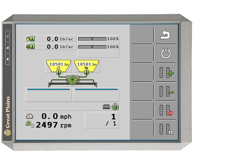
Chapter 1 DrillCommand Overview

1       DrillCommand at a Glance
        What is DrillCommand?
        Great Plains’ DrillCommand software is used with all Great Plains drills and their components.
        DrillCommand regulates, monitors and controls the drill and its features. You can also
        troubleshoot any issue with your machine from the comfort of your cab by using
        DrillCommand’s built-in diagnosis tools.
        Run Your Machine, Your Way
        With DrillCommand on your machine, superior performance, consistency, and reliability are at
        your fingertips. DrillCommand is designed to make your machine start, run, resume, and shut
        down faster and easier.
        DrillCommand also offers extreme flexibility. Need to use your drill for multiple different seeds?
        No problem. With precise hopper control and many customizable configurations,
        DrillCommand lets you get more out of your Great Plains drill than ever before.
1.1 Overview of This Guide
        This guide describes how to use Great Plains’ DrillCommand virtual terminal (VT) software,
        including a quick start guide and a full listing of all settings and features.
        This guide does not include information on hooking up cables from your drill to the tractor or
        terminal and does not describe any of the physical features of your specific terminal. Refer to
        the product’s owner manual for further information.
        Refer to the quick start guide included at the front of this manual and get your drill running in
        the field.

        Read through this manual thoroughly before starting up DrillCommand on your machine and
        making any adjustments to the factory settings and configuration.

1.1.1 Software Version
        DrillCommand’s software release version is identified by an eight digit number, e.g. 02.xx.xx.35
        This release number can be located by selecting the ECU button on the diagnostic settings
        menu.

1.1.2 Maintenance
        No regular maintenance is required for this software. However, it is recommended that you
        have your software checked at least once a year and check our online website for any
        corresponding changes to this manual.
        To install software updates, check with your Great Plains dealer annually to see if updates are
        needed.

DrillCommand | Version 02.02.02.00 - 02.02.03.00 | 2021-05-27                                           7
Chapter 1 DrillCommand Overview

1.1.3 Display Screen

        Power
        Once your virtual terminal is powered on, DrillCommand will load automatically onto your
        terminal’s display screen. If not, tap                  to bring up the DrillCommand home screen.
        From the home screen you can tap           to power on your drill.

        For powering up your terminal, please refer to your terminal’s user guide. If any errors are
        detected, an audible alarm and error warning will display.

        Navigation
        With the use of a virtual terminal (VT), you can enter and retrieve any information you need
        from your DrillCommand system as well as navigate to additional settings and features. All
        screens contain navigation icons that you can tap to move to the next screen and most contain
        a previous screen icon        that will take you back to your last screen.

        Use the         soft key to cycle through multiple options on the same page, e.g. Product 1,
        Product 2. Such screens frequently identify which group is being displayed with a number at
        the top of the screen. This soft key is not available on all screens.

        Online versions of this manual come with interactive screens, so you can navigate through the software
        like you would on an actual terminal. Go to our website and open this guide with any PDF viewer on your
        computer, smartphone, or tablet and look for the information page inside the cover to get started.

        Making Changes
        Entering new or changing information is done by tapping a numerical field on your screen and
        tapping on the screen again with the desired settings. Once the correct setting is entered, tap
        on your screen’s confirmation key, e.g. ‘Enter’ or ‘OK’, to confirm and finish.

DrillCommand | Version 02.02.02.00 - 02.02.03.00 | 2021-05-27                                                 8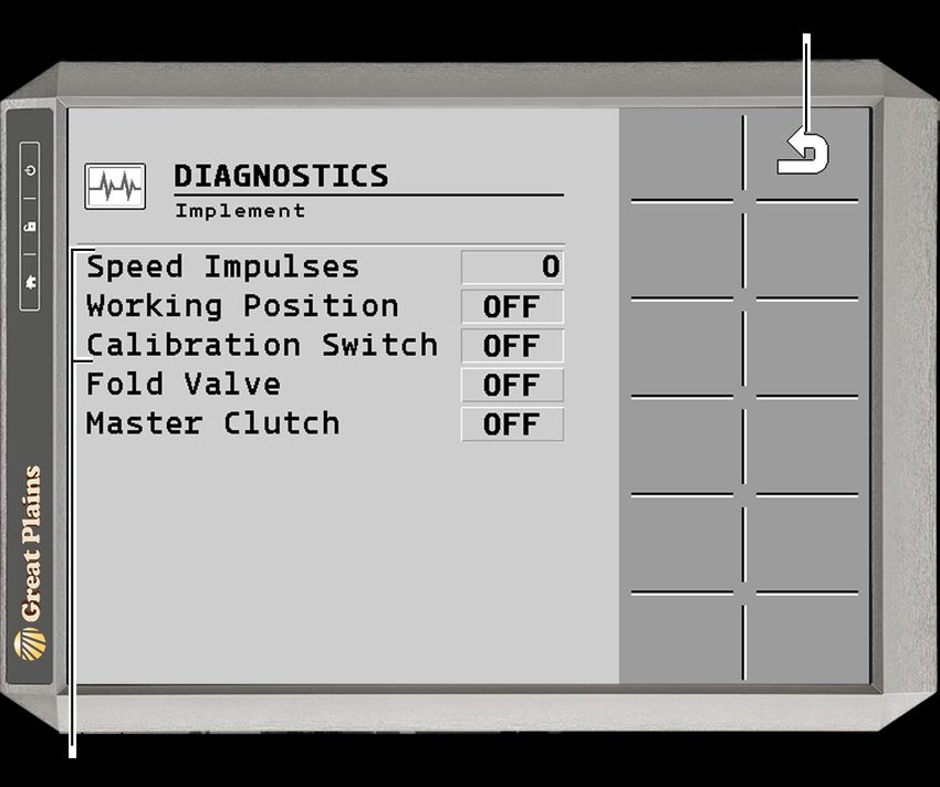
Chapter 2 Quick Start Guide

2       Quick Start Guide
        DrillCommand comes preset from our Great Plains factory for your machine. Most of the
        settings therefore come preconfigured. However, the following inputs are required to begin
        operation: seed rate, calibration, and ground speed constant.
2.1 Initial Start Up and Navigation
        After you have started your terminal and loaded DrillCommand, you will need to navigate to
        the machine settings menu and set-up your drill’s seed rate, calibration factor, and ground
        speed. Once you have set-up this initial task profile, you will not need to perform the set-up
        again unless you make changes to the profile or create a new one.

2.1.1 Home, Setting, and Calibration Screen
        Here’s how to get started quickly with setup:
        In order to navigate to the machine settings menu from the home screen, click on the gear icon
        towards the bottom of your screen.

        After tapping the icon, you will see the machine settings menu screen with icons for further
        setting options. For this quick start guide, we will be working with: speed calibration, tramline,
        hopper, adding a product, and metering. We’ll start with speed calibration first, so tap on the
        Speed Settings icon.

         Tramline     Hopper   Metering

                                                 Previous
                                                 Screen
           Speed         Machine Configuration
           Settings      Menu

DrillCommand | Version 02.02.02.00 - 02.02.03.00 | 2021-05-27                                           9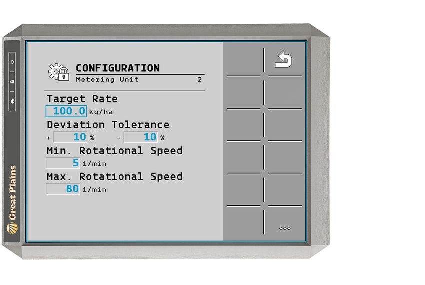
Chapter 2 Quick Start Guide

2.1.2 Calibrate Speed
        Tap the Calibrate Speed soft key icon on the Speed Settings page to start a speed calibration
        run.

        Follow the directions on the screen and mark a distance of 91.5 meters (300 feet) in ground
        conditions which are representative of where the drill will be used. Once the distance is
        marked, tap         to start calibration.

        Drive your tractor to the marker previously set. Your terminal will display the number of
        impulses. Tap to accept the number or to reject and start a new calibration.
        The number of impulses shown should range between 5,000 and 15,000. If your results are
        outside of this range, perform a new calibration run.

DrillCommand | Version 02.02.02.00 - 02.02.03.00 | 2021-05-27                                     10
Chapter 2 Quick Start Guide
2.1.3 Tramlines
Note: This section is applicable only for
machines equipped with tramlines
Set Bout Length. If you have a preset bout you would like to use, enter the reference number
in the ‘RhNo’ field. The reference number will automatically fill in length and the left and right
tramline rhythms. If you want to use a custom rhythm, enter 999 in the ‘RhNo field and
manually input the bout length of the machine and the left and right pass count.
Select Sensor Numbers. Select which rows on the left-hand and right-hand sides of the
machine you want to turn off during tramlining. Ensure tramlines on machine are moved to the
specified rows. Turning off more machine rows creates wider tramlines.
2.1.4 Hoppers
Hopper Display
Hopper
Control
Previous
Screen
Settings Adjustment
Hopper Control. Tap the icon to turn individual hoppers ‘on’ or ‘off.’ If a hopper is off, you
will see a over the hopper display’s product icon.
Settings Adjustments
Associated Product. Underneath the hopper you want to assign a product to, tap on the
product field underneath ‘Associated Product’ and select the hopper’s product type from the
drop-down list. This drop-down list is where you will select the product added in the Add a
Product section of the Quick Start Guide.
Succession Hopper. If you are using the same product in both hoppers and want one hopper
to not run until the first hopper is empty, set a succession hopper. Tap inside the second
hopper’s succession hopper field and change ‘None’ to the hopper you want to use after the
primary hopper is empty. If both hoppers are set to ‘None’ then both meters will run
simultaneously.
Associated Shoot. Set which shoot is selected for each hopper. For single shoot, both will be
set to ‘1.’
DrillCommand | Version 02.02.02.00 - 02.02.03.00 | 2021-05-27 11Chapter 2 Quick Start Guide
2.1.5 Add a Product
Tap the Product Database soft key icon on the Product Configuration page to start adding a
product.
Product
Database
Switch
Meter
Previous
Screen
Tap the Add Product soft key to bring up the Product Configuration page.
Product
Add
Product
Delete
Switch
Meter
Previous
Screen
Primary
Products
Renaming. Assigns the name to the product being created. Tap the box and use the keyboard
to rename the new product.
Product Type. Assigns the type of product. Tap and select from the available drop down list.
Target Rate. Select desired units and choose the rate of application.
Target Rate Increment. Sets increment of original rate by which and keys adjust the
target rate.
Calibration Factor. Sets the amount of product metered per revolution. This value will be
overridden during meter calibration. See Meter Calibration in the Metering section of the Quick
Start Guide.
Switch Meter. Switches between meter settings. To see individual meter drive section
calibration rates, navigate to the meter settings screen.
To select a product you have created, see Associated Product under the Hopper section of the
Quick Start Guide.
DrillCommand | Version 02.02.02.00 - 02.02.03.00 | 2021-05-27 12Chapter 2 Quick Start Guide
2.1.6 Metering
Meter Display
Meter
Calibration
Previous
Screen
Adjustable Calibration
Settings
Adjustable Meter Settings
Select the field underneath ‘Target Rate’ and enter the rate you are wanting to plant at. The
values for your ‘Calibration Factor’ will be found by running a calibration test. Use Product Rate
manual to enter an appropriate initial calibration factor before starting the first calibration.
Great Plains recommends performing calibrations to determine correct calibration factors.
Meter Calibration. To start your calibration run, from meter settings, enter your desired rate.
Tap to begin the corresponding hopper’s calibration routine.
Metering
Drive
Sections
Run
Calibration
Previous
Screen
Make sure that hydraulic flow to the motors is on if using hydraulic motors. Enter your desired
travel speed. You can tap to run one test revolution with the speed selected.
DrillCommand | Version 02.02.02.00 - 02.02.03.00 | 2021-05-27 13Chapter 2 Quick Start Guide
Tap to run the calibration. If the calibration is in the process of running, you should see the
following calibration running screen:
This screen will automatically go to
the calibration confirmation screen
once you have finished running the
machine calibration.
Once the terminal is on the calibration running screen, go to the machine and locate the
calibration bag and scale. Place the empty bag onto the scale and zero out the scale so that the
bag’s weight is not included in the calibration. Then mount the calibration bag to the machine’s
calibration port. Locate the calibration button. Tap this button to begin metering and catching
the product. Release the calibration button when a reasonable sample has been collected.
Unmount the bag from the machine and weigh it.
Go back to the terminal. Once the calibration button is released on the machine, you should
have a new screen appear on the terminal.
Enter the weight in the box that appears after the calibration button is released. After this
weight is entered, a speed range will appear at the bottom of the screen. If this speed range
fully encompasses your desired travel speed, tap to confirm your calibration settings. If the
results are not what you need, tap to cancel the settings and start a new calibration run.
If the speed range is too low or high, consider changing the gear range. After any change,
another calibration routine must be performed.
For more information on your machine’s calibration process, refer to your operator manual.
DrillCommand | Version 02.02.02.00 - 02.02.03.00 | 2021-05-27 14Chapter 2 Quick Start Guide
2.1.7 Running DrillCommand
Once calibration is complete, return to the home screen by using the icon. When you are
on the home screen, go ahead and lower the machine’s openers. If applicable, ensure that the
hopper lids are closed and then turn on the fan. Then tap to turn on the drill.
If you see this screen and all the outputs look correct, your machine is prepared to run.
DrillCommand | Version 02.02.02.00 - 02.02.03.00 | 2021-05-27 15Chapter 3 Terminal Configuration (ISOBUS)
3 Terminal Operation and Configuration
Normal operation of your Great Plains machine does not require anything more than running
through the Quick Start guide. However, a wide variety of controls are available so you can
customize your machine’s basic operation and applications.
Changing Monitor and System Settings
All of DrillCommand’s system settings are accessible through your terminal. These settings are
broken down into the home screen and three different menus.
Home Screen Menu
See page 16 for a complete home screen overview.
Machine Settings Menu
See page 24 for a complete machine settings overview.
Machine Configuration Menu
See page page 40 for a complete machine configuration overview.
Machine Diagnostics Menu
See page page 58 for a complete machine diagnostics overview.
From the home screen, you can go to machine settings by tapping on . From the machine
settings & configuration menu you can access all of DrillCommand’s settings for your machine
and its software.
Language, time, and date settings and units use the terminal’s settings. Refer to your terminal’s
user guide to alter these settings if necessary.
Access More Settings
DrillCommand is factory set to only display the most commonly used machine controls. These
basic controls are easy and quick to alter. However, you can access more of your machine’s
settings by changing the user access level.
To access the user access level from the home screen, go to machine settings -> configuration
settings -> passwords and enter the code for the level of access you need.
These changes should not be made without extensive knowledge of the machine and its
software as they can cause the machine to become inoperable. Great Plains recommends
having a dealer perform any changes to these settings for you.
DrillCommand | Version 02.02.02.00 - 02.02.03.00 | 2021-05-27 17Chapter 3 Terminal Configuration (ISOBUS)
3.1 Home Screen Menu
Your terminal will automatically load the software from the machine’s ECU. Startup will vary
depending on the terminal used: either the program will start immediately or the terminal’s
button for an ISOBUS-connected device appears. Tap the start icon or press the ISOBUS button
to start the program if necessary.
Operation and navigation of software requires the use of a touchscreen terminal. Terminals that
navigate between screens with the use of a dial will not function properly.
You will find all important data on the machine’s operation, settings, etc. presented clear and
concise on this screen.
Home Screen
Interactive icons are enabled. Click on an icon to go directly to the icon’s screen.
Home Screen Overview
When you start DrillCommand, the home screen initially opens. The home screen is your
starting point for all settings and features on your drill. It displays machine information and has
navigation icons that take you to your machine’s settings, configurations, and diagnostics.
On right-hand side of the screen, the softkey bar will have all of your navigation icons. You can
tap machine settings to view even more navigation possibilities and options.
The home screen is the view you will see while seeding. You can see all important information
for monitoring the machine from this screen and navigate to settings.
DrillCommand | Version 02.02.02.00 - 02.02.03.00 | 2021-05-27 18Chapter 3 Terminal Configuration (ISOBUS)
Soft Key Icons
Master Switch. Tap to turn control of your drill on and off.
This soft key control is not available on all screens. Turn off the master switch whenever
you exit the tractor.
Results Information.Tap for trip and season counters.
For further information on results information see page 22.
Frame Control. Tap to open the frame control window.
This soft key control is not available on all screens.
Machine Settings. Tap to alter machine settings.
For further information on machine tools see page 26.
Informational Icons
Lift Switch Indicator. Shows whether the lift is set to raise or lower. If the icon is crossed
out and circled in red, then the machine is raised and not ready for planting. When red
marker is absent, the machine is lowered and ready to plant.
Master Switch Indicator. The green on icon indicates the machine is on and currently
running. The red off icon indicates the machine is off and not running. Running the
machine is controlled through the machine control icon.
Alarm Indicator. Displays when an alarm is registered. For more information, see your
alarms list in machine diagnostics.
Blockage Indicator. Displays when a row is blocked when a blockage system is installed
on the machine.
Current Ground Speed. Located to the right of the icon is current ground speed
measured in kilometers per hour.
Current Fan Speed. Located to the right of the icon is current fan speed measured in
revolutions per minute.
Home Screen Controls
Meter Rate. Tap or to adjust meter 1 or 2’s rate by entering a value. The amount of
mass of product used per area covered is displayed. Each icon controls a unique meter and is
distinguishable by the number on the icon’s body as well as the material type.
Frame Control. Tap on to open the frame control window. Tapping on the fold/unfold
icon will highlight the icon with a . This box indicates the terminal’s fold/unfold
control is on. To turn off the terminal’s control of folding and unfolding, simply tap the fold /
unfold icon again. If successful, will disappear from around the fold/unfold icon.
DrillCommand | Version 02.02.02.00 - 02.02.03.00 | 2021-05-27 19Chapter 3 Terminal Configuration (ISOBUS)
Tramline Bout
If tramlining option is turned on, tap to bring up the bout length controls in your soft key bar.
Interactive icons are enabled. Click on an icon to go directly to the icon’s screen.
You should see a new set of soft keys in your bar for adjusting your machine’s bout length. The
home screen will remain the same as shown below.
Bout On/Off Switch. Tap to turn bout controls on or off.
Bout Length Controls. There are four different control buttons for adjusting your bout length:
adds a single bout.
subtracts a bout.
suspends tramlining.
goes to the tramline settings screen. See page 26 for a complete overview of tramline settings.
DrillCommand | Version 02.02.02.00 - 02.02.03.00 | 2021-05-27 20Chapter 3 Terminal Configuration (ISOBUS)
Machine Control
Tap the master switch to turn control of your drill on and off.
Interactive icons are enabled. Click on an icon to go directly to the icon’s screen.
Section Hopper Meter Hopper
Control Selection Rate Display
Master
Switch
Hopper Display. Provides a graphical representation of each hopper’s status. Hopper number,
type of product, and weight of product present are all shown on the display. Tap on any hopper
to display detail hopper info. Order of the feedback shown on the hopper info display and what
type of feedback shown can be adjusted in the feedback configuration screen.
Meter Increase. Tap to increase the amount of product by the preconfigured
percentage.
Go to Metering Settings on page 32 for information on altering the adjustment rate.
Meter Decrease. Tap to decrease the amount of product by the preconfigured
percentage.
Go to Metering Settings on page 32 for information on altering the adjustment rate.
Meter Reset. Tap to reset all meters to 100 percent.
Pre-start. Tap to prime the meter for seeding. If not primed, seed will not plant for several
feet after configuration. Pressing this will set the meter to run at the correct rate for 5 seconds
or until primed.
Section Control (Option). If section control is installed, tap underneath your
screen’s implement graphic. From the section control window, adjust settings for the selected
section of your machine.
If section control is not installed on the machine, the section control icons will be inactive.
Please note that your screen’s sections are oriented left to right when facing the rear of the machine.
DrillCommand | Version 02.02.02.00 - 02.02.03.00 | 2021-05-27 21Chapter 3 Terminal Configuration (ISOBUS)
3.1.1 Results Information
Results information is viewable by tapping on from the home screen.
Results Information Screen
Interactive icons are enabled. Click on an icon to go directly to the icon’s screen.
Clear
Trip
Clear
Season
Total
Results
Previous
Screen
Meter
Counters
Results Information Overview
The results information screen allows you to record trip and season counters or clear the results
of your previous trips and start again from 0. Total results are also recorded and viewable on a
separate screen by clicking on the ‘Total Results’ icon.
Once cleared, you will not be able to retrieve your trip or season information. Record any information
you do not want to lose before proceeding with clearing counters. Total results will remain unchanged.
DrillCommand | Version 02.02.02.00 - 02.02.03.00 | 2021-05-27 22Chapter 3 Terminal Configuration (ISOBUS)
Soft Key Icons
Previous Screen. Tap to return to the previous screen.
Use this icon multiple times to return to the home screen.
Clear Trip. Tap to reset the trip counter.
This soft key control is not available on all screens.
Clear Season. Tap to reset the season counter.
This soft key control is not available on all screens.
Total Results. Tap to go to the total results screen.
This soft key control is not available on all screens.
Meter Counters
Your meter counters track two different counters: trip and season. Results for trip and season
counters display the area and distance covered per session or season. Tap on either clear trip or
clear season to clear the corresponding counter.
Total Results Screen
Interactive icons are enabled. Click on an icon to go directly to the icon’s screen.
Total Results Previous
Information Screen
Total Results Information. An overall summary of your implement usage is recorded and
displayed on this screen. Results of your total time, distance, area, and quantity of product will
show. You can also see at the top of this screen the total number of hours your electronics have
been turned on.
DrillCommand | Version 02.02.02.00 - 02.02.03.00 | 2021-05-27 23Chapter 3 Terminal Configuration (ISOBUS)
3.1.2 Blockage Sensor View.
Tap from the home screen to enable Blockage Sensor View.
Implement
View
Machine
Settings
Menu
Blockage Sensor
View
Blockage Sensor View. Shows blockage performance by section. Tap blockage sensor view
area to zoom in on individual sensors. If there are enough sensors, black arrows on the left and
right will scroll through each sensor. In the alternate zoom view, select the bar at the top to
cycle through shoots. A green rectangle shows normal operation. A red oval shows a blocked
sensor.
Implement View. Tap to return to Implement View on the home screen.
DrillCommand | Version 02.02.02.00 - 02.02.03.00 | 2021-05-27 24Chapter 3 Terminal Configuration (ISOBUS)
3.2 Machine Settings Menu
The machine settings menu is found by tapping from the home screen.
Machine Settings Menu Screen
Interactive icons are enabled. Click on an icon to go directly to the icon’s screen.
Tramline Hopper Metering
Fan
Previous
Screen
Weigh Speed Configuration Blockage Diagnostics
System Menu Menu
Machine Settings Overview
Change a setting by tapping on any of the appropriate sub menus and pressing a field with a
value. You can either select a new value or enter a number from the screen’s popup keypad and
confirm your selection.
Your Great Plains drill comes preconfigured with the appropriate settings for your machine. You
can also adjust the settings on different features in this menu such as metering, tramlines,
blockage systems, etc.
DrillCommand | Version 02.02.02.00 - 02.02.03.00 | 2021-05-27 26Chapter 3 Terminal Configuration (ISOBUS)
Soft Key Icons
Previous Screen. Tap to return to the previous screen.
Use this icon multiple times to return to the home screen.
Sub Menus
Tramline Settings. Create different types of tramlining. Input a unique reference
number to save and switch between different tramline settings.
See page 28 for a complete overview of tramline settings.
Hopper Settings. Select product type and settings for each hopper. Use this setting to
turn off individual hoppers.
See page 32 for a complete overview of hopper settings.
Meter Settings. Specify target rate per amount of ground covered and perform and
record results of a calibration run for individual meters.
See page 34 for a complete overview of meter settings.
Weigh System Settings. View and input weight in each hopper.
See page 38 for a complete overview of weigh system settings.
Blockage Sensor View. Adjust blockage system sensitivity or set sensitivity to 0 to turn
off alarms. Blockage settings can also be reached through the home screen.
See page 40 for a complete overview of blockage settings.
Speed Settings. Set speed system’s sensor calibration factor or select speed input source.
See page 42 for a complete overview of speed settings.
Configuration Menu. Displays the configuration sub menu options.
See page 46 for a complete overview of the configuration menu.
Diagnostics Menu. Displays the diagnostics sub menu options.
See page 64 for a complete overview of the diagnostics menu.
DrillCommand | Version 02.02.02.00 - 02.02.03.00 | 2021-05-27 27Chapter 3 Terminal Configuration (ISOBUS)
3.2.1 Tramline Settings
Tramline settings are located by tapping on from the machine settings menu.
Tramline Settings Screen
Interactive icons are enabled. Click on an icon to go directly to the icon’s screen.
Tramline Settings Overview
Tramlines are produced by closing corresponding tower outlets or turning off feeder cups.
Adjust settings by inputting a new reference number and tramline bout lengths and
alternation. These settings can either be adjusted with a custom rhythm or by using one of
DrillCommand’s preset tramline configurations. Illustrated charts for these preset tramlines are
available on page 30. You can also adjust the tramline sensors from this screen.
DrillCommand | Version 02.02.02.00 - 02.02.03.00 | 2021-05-27 28Chapter 3 Terminal Configuration (ISOBUS)
Soft Key Icons
Previous Screen. Tap to return to the previous screen.
Use this icon multiple times to return to the home screen.
Installing Tramline Equipment
In addition to your terminal and DrillCommand software, you must fit your machine with
tramline motors that will shut off the flow of seed to the desired openers. You can find more
information about these tramline kits in your operator’s manual.
Tramline Settings
Use the tramline settings to create or customize your tramlines. Set a bout length that will suit
your needs or use a length from a preset tramline setting. A bout constitutes a number of
passes you will make up and down the field as you are planting.
If you are using a custom rhythm setting, tapping in the fields under ‘Left’ and ‘Right’ will allow
you to set which pass during the bout will be tramlined. If you are using a preset tramline
rhythm, tapping in the ‘Left’ and ‘Right’ fields will open the tramline reference numbers.
Sensor Settings
Total Closed Openers. You can select which sensors are turned off during bouts in the ‘sensors
number’ fields. Enter the number of each sensor that you want to close for all tracks formed on
that side of your drill.
Track Spacing. In addition to closing openers, you will need to determine how much space to
put between each tramline track. This distance should be the width from one inside tire edge
on your sprayer/fertilizer applicator to another.
For more information on calculating the total number of openers to close and track spacing,
see Tramline Configuration on page 54.
The number of passes per bout that your tramline rhythm needs depends on your sprayer/
fertilizer’s working width divided by your drill’s working width. If unsure of how to create
tramlines, refer to the tramline charts later on in this section.
Preset Rhythm Settings
You can enter a unique number for preset tramline settings. These rhythms are configured for
various drill and applicator lengths for determining the appropriate patterns and bout lengths.
To use one of these preset rhythms, tap on the ‘RhNo’ field and scroll through and select the
rhythm you wish to use.
To view the rhythms available for your drill and applicator widths, see the tramline charts later
on in this section.
Custom Rhythm Settings
Entering the number ‘999’ into the RhNo box field will allow you to create a custom tramline
rhythm.
DrillCommand | Version 02.02.02.00 - 02.02.03.00 | 2021-05-27 29Chapter 3 Terminal Configuration (ISOBUS)
Symmetrical Tramline Rhythms
Rhythm RhNo Tramline Bouts
3 3 1 3
2
3 3 2 2
4 4S 1 3
2 4
4S 4 2 2
5 5 1 3 5
2 4
5S 5 3 3
6 6S 1 3 5
2 4 6
6S 6 3 3
7 7 1 3 5 7
2 4 6
7S 7 4 4
8 8S 1 3 5 7
2 4 6 8
8S 8 4 4
9 9 1 3 5 7 9
2 4 6 8
9 9 5 5
Half Width Tramline Tractor
Tramline Pass Tracks Model
DrillCommand | Version 02.02.02.00 - 02.02.03.00 | 2021-05-27 30Chapter 3 Terminal Configuration (ISOBUS)
Asymmetrical Tramline Rhythms
Rhythm RhNo Tramline Bouts
3 999 1 3
2
999 3 1 2
4 999 1 3
2 4
999 4 2 3
5 999 1 3 5
2 4
999 5 2 3
6 999 1 3 5
2 4 6
999 6 3 4
7 999 1 3 5 7
2 4 6
999 7 3 4
8 999 1 3 5 7
2 4 6 8
999 8 4 5
9 999 1 3 5 7 9
2 4 6 8
999 9 4 5
Half Width Tramline Tractor
Tramline Pass Tracks Model
DrillCommand | Version 02.02.02.00 - 02.02.03.00 | 2021-05-27 31Chapter 3 Terminal Configuration (ISOBUS)
3.2.2 Hopper Settings
Hopper settings are found by tapping from the machine settings menu.
Hopper Settings Screen
Interactive icons are enabled. Click on an icon to go directly to the icon’s screen.
Hopper Display
Hopper
Control
Previous
Screen
Settings Adjustment
Hopper Settings Overview
Alter hopper settings by adjusting individual hoppers with their meter types, succession
hopper and associated shoot. Each hopper can be turned off or on by tapping on their
associated hopper control icon.
Use the hopper displays to review information for the associated hopper.
DrillCommand | Version 02.02.02.00 - 02.02.03.00 | 2021-05-27 32Chapter 3 Terminal Configuration (ISOBUS)
Soft Key Icons
Previous Screen. Tap to return to the previous screen.
Use this icon multiple times to return to the home screen.
Hopper Control. Tap to turn the corresponding hopper on or off. Hoppers that are
turned off will have their hopper display’s number crossed out with a red ‘X’.
Hopper Selection. Tap to cycle through available hoppers. This soft key control is not
available on all screens.
Settings Adjustments
Hopper Display. If no weigh system is fitted, you can manually enter the weight you added.
Here, and on the main display, the weight will go down as you seed based on the calculated
product applied.
If you machine has a weigh system installed, the amount weighed will be shown here as well.
Associated Product. Tap to give a drop down list of possible product types you can assign to a
hopper.
Associated Shoot. Tap on associated shoot to set which shoot the hopper will use. Multiple
hoppers can go to the same shoot. Default settings have seed go in shoot 1 and fertilizer in
shoot 2. Before altering any settings, check your machine’s shoot setup and seed hose
connection to the cart.
Hopper Display
Hopper
Control
Previous
Screen
Meter Switch
Sections Hopper
From here you can see individual meter sections’ content. Tapping the arrow keys will switch to
a remaining area measurement.
DrillCommand | Version 02.02.02.00 - 02.02.03.00 | 2021-05-27 33Chapter 3 Terminal Configuration (ISOBUS)
3.2.3 Metering Settings
Meter settings are found by tapping on from the machine settings menu.
Metering Settings Screen
Interactive icons are enabled. Click on an icon to go directly to the icon’s screen.
Meter Display
Meter
Calibration
Previous
Screen
Adjustable Calibration
Settings
Metering Settings Overview
You can use this screen to adjust metering rate and adjustment amounts. Select and enter new
values for your target rates and then perform a calibration run. Properly calibrating the meter
for each hopper is necessary for operation. We recommend you run a calibration test for each
crop you plant at least once per season.
Before you begin calibration, make sure that your tractor is parked and the drill is easily and
safely accessible.
DrillCommand | Version 02.02.02.00 - 02.02.03.00 | 2021-05-27 34Chapter 3 Terminal Configuration (ISOBUS)
Soft Key Icons
Previous Screen. Tap to return to the previous screen.
Use this icon multiple times to return to the home screen.
Meter Calibration. Tap to go to the meter calibration screen.
Further information on meter calibration is described later on in this section.
Next Meter. Tap to go to the next meter.
Adjustable Meter Settings
Tap on the target rate numerical field to enter a rate for your meter. It is necessary to use the
machine operator manual to determine which calibration factor to start with before calibrating.
Manually enter this rate in the calibration factor numerical field. The target rate increment is the
percentage of unit of adjustment you want to make from the home screen when adjusting the
rate up or down.
Metering Calibration
You can manually enter a calibration factor, but Great Plains strongly recommends you perform a
calibration for each crop or meter roller change. To start your calibration run, from meter settings,
enter your desired rate. Tap to begin the corresponding hopper’s calibration routine.
Interactive icons are enabled. Click on an icon to go directly to the icon’s screen.
Metering
Drive
Sections
Run
Calibration
Previous
Screen
Box Drill Calibration
On box drill models, the calibration screen replaces filling meter with a field for entering the
number of rows to be collected from. To set this number, count the number of rows that will
DrillCommand | Version 02.02.02.00 - 02.02.03.00 | 2021-05-27 35Chapter 3 Terminal Configuration (ISOBUS)
pour seed into your calibration container and enter that number into the ‘No. of Rows’ field.
Number of rows varies between models’ row spacings.
If using hydraulic motors, make sure that hydraulic flow to the motors is on. Enter your desired
travel speed. Select your desired metering drive section by selecting the key. This selection
will be the only section calibrated. Calibrate all sections before planting.
Previous
Screen
You can tap to run one test revolution with the speed selected.
Tap to run the calibration. If the calibration is in the process of running, you should see the
following calibration running screen:
Releasing the calibration button on
the machine will cause the screen to
progress to calibration confirmation.
Click the button to progress to the
next screen.
DrillCommand | Version 02.02.02.00 - 02.02.03.00 | 2021-05-27 36Chapter 3 Terminal Configuration (ISOBUS)
Once the terminal is on the calibration running screen, go to the machine and locate the
calibration bag and scale. Mount the calibration bag to the machine’s calibration port. Locate
the calibration button. Engage this button to begin metering and catching the product.
Release the calibration button when a reasonable sample has been collected. Unmount the
bag from the machine and weigh it.
Go back to the terminal. Once the calibration button is released on the machine, you should
have a new screen appear on the terminal.
Interactive icons are enabled. Click on an icon to go directly to the icon’s screen.
Enter the weight in the box that appears after the calibration button is released. After this
weight is entered, a speed range will appear at the bottom of the screen. If this speed range
fully encompasses your desired travel speed, tap to confirm your calibration settings. If the
results are not what you need and/or you don’t want to enter the values manually, tap to
cancel the settings and start a new calibration run.
If the speed range is too low or high, consider changing the gear range found on the side of the
meters or the metering drums themselves. After any change, another calibration routine must
be performed.
DrillCommand | Version 02.02.02.00 - 02.02.03.00 | 2021-05-27 37Chapter 3 Terminal Configuration (ISOBUS)
3.2.4 Weigh System Settings
Weigh system settings are found by tapping on from the machine settings menu.
Weigh System Settings Screen
Interactive icons are enabled. Click on an icon to go directly to the icon’s screen.
Previous
Screen
Hopper Weight
Display Increase
Weigh System Settings Overview
If your machine is fitted with weigh cells, you can use this screen to send an alert when you are
exceeding a set amount of product. To do this, select a field underneath ‘Add Weight’ and enter
the amount of product you plan to add.
The current hopper weight is shown in the hopper display area.
DrillCommand | Version 02.02.02.00 - 02.02.03.00 | 2021-05-27 38Chapter 3 Terminal Configuration (ISOBUS)
Soft Key Icons
Previous Screen. Tap to return to the previous screen.
Use this icon multiple times to return to the home screen.
Information and Settings
Hopper Display. This graphic will show information on individual hoppers and how much
weight of a product is detected.
Weight Increase. To have the terminal send out an alert when you’ve added a predetermined
amount of product, select one of the fields underneath ‘Add Weight’ and enter the amount of
product you plan to add to the corresponding hopper.
After entering and accepting the weight value, will appear. Press this icon to start the
system looking for a change in product amount, once the user-defined amount of weight has
been reached you can confirm by tapping on in the soft key area or on the alert message.
As the hopper fills, the screen will display the amount of product left to fill.
Virtual Hopper. If your machine is not fitted with weight cells, you can use this feature to track
seed weight. To do this, select a hopper and adjust the Content field to the amount of product
you have added to the hopper. The machine will calculate seed usage based upon the
calibration you have set. To cross reference the weights between your scale system and the
virtual hopper, make sure both features are turned on. You will be able to equalize the
calculated and measured weights with the newly displayed soft key.
DrillCommand | Version 02.02.02.00 - 02.02.03.00 | 2021-05-27 39Chapter 3 Terminal Configuration (ISOBUS)
3.2.5 Blockage System Settings
Blockage settings are found by tapping from the machine settings menu.
Blockage System Settings Screen
Interactive icons are enabled. Click on an icon to go directly to the icon’s screen.
Sensitivity Shoot Previous
Setting Selection Screen
Blockage Settings Overview
Adjust sensitivity by scaling the setting for each meter. Increasing the position of the slider on
the scale or entering in a value from 1 to 10 will increase the sensitivity of the drill’s sensors. You
can also turn off the blockage system alarm from this screen by setting the sensitivity level of
the alarms to 0.
DrillCommand | Version 02.02.02.00 - 02.02.03.00 | 2021-05-27 40Chapter 3 Terminal Configuration (ISOBUS)
Soft Key Icons
Previous Screen. Tap to return to the previous screen.
Use this icon multiple times to return to the home screen.
Sensitivity Setting
Setting Adjustments. Adjust the value of each sensitivity setting by tapping on the field with
the scale’s value and entering a value between 1 and 10 or by tapping on the scale. The scale is
divided into ten separate levels according to the markers on the bottom edge. The larger end of
each scale indicates a higher sensitivity level. Tap the box below the sensitivity number to
select product type.
Alarm Warnings Off. To turn off the alarm warnings, set the value of the sensitivity level to 0.
Disable Sensors. No: No alarms disabled.
Odd: Disable only odd numbered row alarms.
Even: Disables only even numbered row alarms.
Custom: Allows the user to select the desired rows to disable for support of tramlines or bad
sensors.
Sensor Delay Time. The amount of time before the system alarms the user after a blockage has
been detected. The default system setting for this feature is set to 3 seconds. The value entered
will add to the 3 second default. Tap the key to move between shoots.
If you have difficulty setting the sensitivity level to 0 by tapping on the scale, try tapping to the
left of the scale’s far-left edge.
DrillCommand | Version 02.02.02.00 - 02.02.03.00 | 2021-05-27 41Chapter 3 Terminal Configuration (ISOBUS)
3.2.6 Speed Settings
Speed settings are located by tapping from the machine settings menu.
Speed Settings Screen
Interactive icons are enabled. Click on an icon to go directly to the icon’s screen.
Calibrate
Speed
Previous
Screen
Adjustable
Speed Settings
Speed Settings Overview
Use this screen to select the implement speed source from the menu and make adjustments as
necessary. Run a speed calibration test and use the result to determine your machine’s
calibration factor. Your DrillCommand software comes with a default setting for the calibration
factor, but Great Plains does not recommend using the default value.
DrillCommand | Version 02.02.02.00 - 02.02.03.00 | 2021-05-27 42Chapter 3 Terminal Configuration (ISOBUS)
Soft Key Icons
Previous Screen. Tap to return to the previous screen.
Use this icon multiple times to return to the home screen.
Calibrate Speed. Tap to go to the speed calibration screen.
Further information on calibrating speed is described later on in this section.
Adjustable Speed Settings
Speed Source. Select your source of speed for the implement to use and determine it’s ground
and meter speed when applying seed. This setting is on ‘Implement’ by default and will cause
your machine to use the on board radar.
If the on board radar malfunctions or gives false readings, you can choose a fixed ‘simulated’
ground speed that is not related to the actual machine travel speed.
The third option for speed source is ‘tractor.’ The speed signal is acquired from the tractor’s
ISOBUS system. Two speed types are available on the ISOBUS from the tractor ECU: wheel
speed and ground speed. You can select the best source for your application.
Getting the ground speed from the tractor should only be done by advanced users.
Simulated Speed. If you are using ‘simulated’ as your speed source, set a simulated speed in this
field.
Calibration Factor. Set the number of impulses per 100 meters, or 300 feet, for your calibration.
DrillCommand | Version 02.02.02.00 - 02.02.03.00 | 2021-05-27 43Chapter 3 Terminal Configuration (ISOBUS)
Calibrate Speed
Tap the Calibrate Speed soft key icon to start a speed calibration run.
Follow the directions on the screen and mark a distance of 91.5 meters (300 feet) in ground
conditions which are representative of where the drill will be used. Once the distance is
marked, tap to start calibration.
Drive your tractor to the marker previously set. Your terminal will display the number of
impulses. Tap to accept the number or to reject and start a new calibration. The number of
impulses shown should range between 5,000 and 15,000. If your results are outside of this
range, perform a new calibration run.
DrillCommand | Version 02.02.02.00 - 02.02.03.00 | 2021-05-27 44Chapter 3 Terminal Configuration (ISOBUS)
3.3 Machine Configuration Menu
The machine configuration menu is found by tapping from the machine settings screen.
Machine Configuration Menu Screen
Interactive icons are enabled. Click on an icon to go directly to the icon’s screen.
Hopper Product
Implement
Meter
Sectional
Shoots
Blockage
Fan
Previous
Screen
Feedback Passwords
Machine Configuration Overview
Alter a configuration by tapping on any of the appropriate sub menus and pressing a field with
a value and entering in a new numeric value. In some cases, you will have to choose between
different options, e.g. ‘on’ or ‘off’, ‘seed,’ ‘fertilizer,’ or ‘liquid’, etc.
After making a selection, you may see an ‘ECU Restarts’ warning. This is normal and allows the
software to load new pages and runs based on your previous selections.
DrillCommand | Version 02.02.02.00 - 02.02.03.00 | 2021-05-27 46Chapter 3 Terminal Configuration (ISOBUS)
Soft Key Icons
Previous Screen. Tap to return to the previous screen.
Use this icon multiple times to return to the home screen.
Sub Menus
Implement Configuration. Configure general implement values. Use this screen to
perform radar and other non-ground speed calibrations and view machine dimensions.
See page 48 for a complete overview of implement configuration.
Hopper Configuration. Change hopper’s associated shoot.
See page 52 for a complete overview of hopper configuration.
Product Configuration. Assign general product configurations. Use this screen to alter
various names and values for things such as name, type, operating speed, target rate,
adjustment, etc.
See page 54 for a complete overview of product configuration.
Metering Configuration. Alter target and maximum allowable speeds for metering.
Changing these settings determines when alarms trigger for exceeding maximum and
minimum values.
See page 56 for a complete overview of metering configuration.
Sectional Shoots Configuration. Configure hopper shoot values. Use to enter number
of sections and rows and the total working width.
See page 58 for a complete overview of sectional shoots configuration.
Fan Configuration. This is not a user adjustable configuration. Controlling the fan speed
is done through your tractor. For more information, see your tractor operators manual.
Tramline Configuration. This is not a user adjustable configuration. Create different
types of tramlining. Use this to configure the sensors for the left and right sides’
tramlines.
Blockage Configuration. This is not a user adjustable configuration. Create loops for
blockage sensors. Use this to create loops for different types of products and assign the
number of sensors that are monitored.
Feedback Configuration. Change the information provided by the home screen.
Passwords. Certain settings for the ISOBUS control system are locked. Contact your
dealer on any questions regarding this feature.
DrillCommand | Version 02.02.02.00 - 02.02.03.00 | 2021-05-27 47You can also read