The ATLAS Tile Calorimeter performance and its upgrade towards the High-Luminosity LHC - Indico
←
→
Page content transcription
If your browser does not render page correctly, please read the page content below
The ATLAS Tile Calorimeter performance and
 its upgrade towards the High-Luminosity LHC
 Ryan Mckenzie, University of the Witwatersrand,
 on behalf of the Tile Calorimeter System

 ryan.peter.mckenzie@cern.ch

 XXVIII International Workshop on Deep-Inelastic Scattering and Related Subjects

 This work is based on research supported in part by the National Research Foundation of South Africa (Grant number: 123017)

Ryan Mckenzie DIS2021
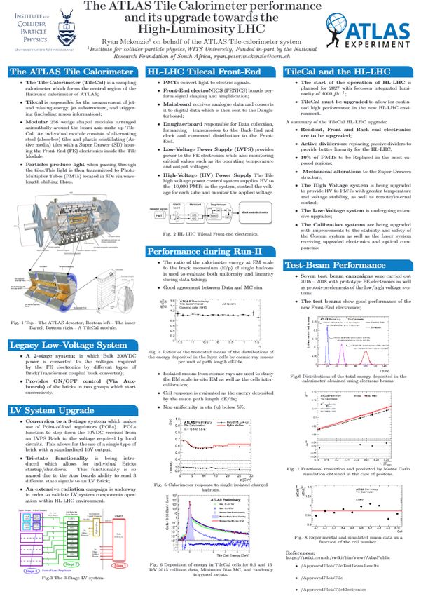
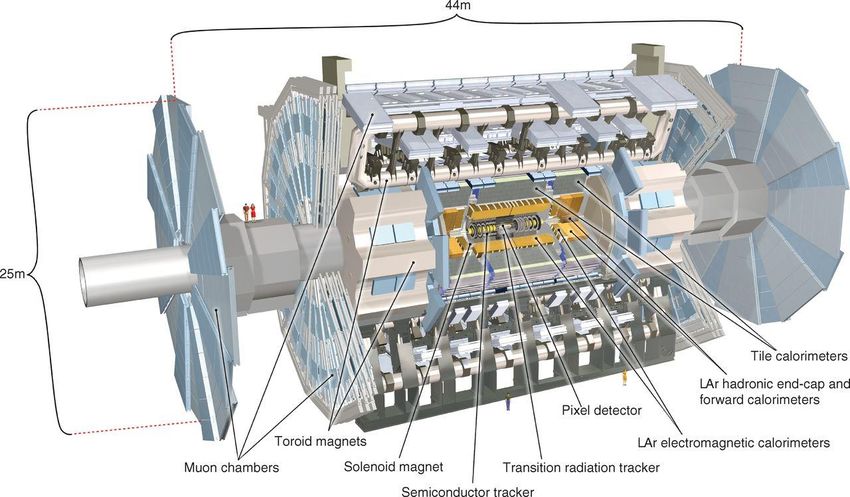
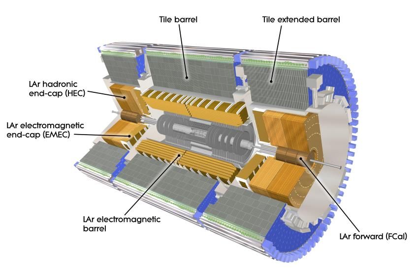
The ATLAS Tile Calorimeter
 • The Tile-Calorimeter (TileCal) is a sampling
 calorimeter which forms the central region of the
 Hadronic calorimeter of ATLAS;

 • TileCal is responsible for the measurement of jet-
 and missing-energy, jet substructure, and triggering
 (including muon information);

 • TileCAL is Modular and consists of 256 wedge
 shaped modules arranged azimuthally around the
 beam axis. An individual module consists of
 alternating steel (absorber) tiles and plastic
 scintillating (Active media) tiles and a Super Drawer
 (SD) which houses the Front-End (FE) electronics.

 • Particles produce light when passing through the
 tiles. This light is then transmitted to Photo-Multiplier
 Tubes (PMTs) located in SDs via wave-length shifting
Ryan McKenzie
 fibers.

 Ryan Mckenzie DIS2021 1
HL-LHC TileCal Front-End
 • PMTs convert light to electric signals.
 • Front-End electroNICS(FENICS) boards perform signal shaping and amplification;
 • Mainboards receives analogue data and convert it to digital data which is then sent to the
 Daughterboard;
 • Daughterboards are responsible for Data collection, formatting, transmission to the Back-End
 as well as clock and command distribution to the Front-End.
 • Low-Voltage Power Supply (LVPS) provides power to the FE electronics while also monitoring
 critical values such as its operating temperature and output voltages;
 • High-Voltage (HV) Power Supply supplies HV to the PMTs in the system, control the voltage
 for each tube and monitors the applied voltage.

Ryan Mckenzie DIS2021 2
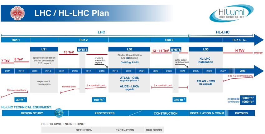
TileCal and the HL-LHC

 https://project-hl-lhc-industry.web.cern.ch/content/project-schedule
 • The start of the operation of HL-LHC
 is planned for 2027 with a foreseen
 integrated luminosity of 4000 −1 ;
 • TileCal must be upgraded to allow for
 continued high performance in the
 new HL-LHC environment.

 A summary of the TileCal HL LHC upgrade:

 • Readout, Front and Back-end electronics are to be upgraded;
 • Active dividers are replacing passive dividers to provide better linearity for the HL-LHC;
 • 10% of PMTs to be Replaced in the most ex-posed regions;
 • Mechanical alterations to the Super-Drawers structure;
 • The High Voltage system is being upgraded to provide HV to PMTs with greater temperature and voltage
 stability, as well as remote/internal control;
 • The Low-Voltage system is undergoing extensive upgrades;
 • The Calibration systems are being upgraded with improvements to the stability and safety of the Cesium
 system as well as the Laser system receiving upgraded electronics and optical components
Ryan McKenzie DIS2021 3
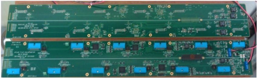
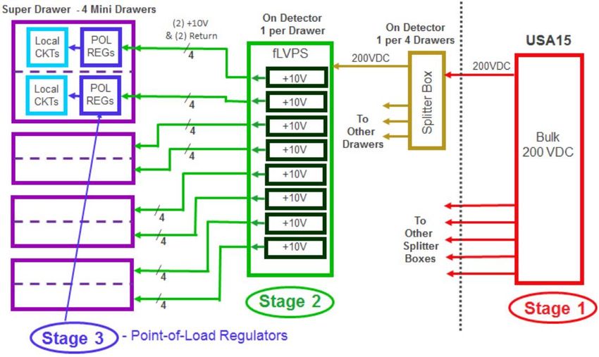
Legacy Low-Voltage System
 • A 2-stage system in which Bulk 200VDC power is

 ATLAS-TDR-028 CERN-LHCC-2017-019, Pg. 111
 converted to the voltages required by the FE electronics
 by different types of Brick(Transformer coupled buck
 converter);
 • Provides ON/OFF control (Via Aux-boards) of the bricks
 in two groups which start successively.

 LV System Upgrade
 • Conversion to a 3-stage system which makes use of
 Point-of-load regulators (POLs). POLs function to step-
 down the 10VDC received from an LVPS Brick to the
 voltage required by local circuits. This allows for the use of
 a single type of brick with a standardized 10V output;
 • Tri-state functionality is being introduced which allows for
 individual Bricks startup/shutdown. This functionality is so
 named due to the Aux-boards ability to send 3 different
 state signals to an LV Brick;
 • An extensive radiation campaign is underway in order to
 validate LV system components operation within HL-LHC
 environment.

Ryan McKenzie DIS2021 4
Performance during Run-II
 Isolated muons from cosmic rays are used to study the EM scale in-
 situ as well as the cells inter-calibration;

 • Cell response is evaluated as the energy deposited by the muon η
 path length dE/dx;
 • Non-uniformity in eta (η) below 5%

 esponse
 tsTileSingleParticleR
 sPublic/ApprovedPlo
 /twiki/bin/view/Atla
 https://twiki.cern.ch
 • The ratio of the calorimeter energy at EM scale to the track
 momentum ⟨E/p⟩ of single hadrons is used to evaluate both
 uniformity and linearity during data taking;

 • Good agreement between Data and MC sim

 on
 tsTileEnergyDepositi
 sPublic/ApprovedPlo
 /twiki/bin/view/Atla
 https://twiki.cern.ch
 • Deposition of energy in TileCal cells for 0.9 and 13 TeV 2015 collision
 data, Minimum Bias MC, and randomly triggered events.

Ryan McKenzie DIS2021 5
Test-Beam Performance

 ApprovedPlotsTileTestBe

 https://twiki.cern.ch/twi
 ki/bin/view/AtlasPublic/
• Seven test beam campaigns were carried out between 2016 – 2018

 amResults
 with prototype FE electronics as well as prototype elements of the
 low/high voltage systems;

• The test beams show good performance of the new Front-End
 electronics;

 amResults#Protons
 ApprovedPlotsTileTestBe
 ki/bin/view/AtlasPublic/
 https://twiki.cern.ch/twi
• The fractional resolution in Data and MC for protons, kaons and
 Pions was obtained with a slight improvement in resolution being
 observed;

• The detector response has been studied determining the ratio

 ileEnergyDeposition
 ublic/ApprovedPlotsT
 twiki/bin/view/AtlasP
 https://twiki.cern.ch/
 between the energy deposited in a calorimeter cell (dE) and the track
 path-length in the cell (dl)

• The data shows a layer uniformity at 1%. An offset of max 4% is
 observed for Data/MC. ATL-COM-TILECAL-2018-002

Ryan McKenzie DIS2021 6
Interactive session
 • Additional slides will be provided to enable discussion of the
 topics introduced.
 • Session 1: 13th of April (Tuesday) afternoon, from 14:15 to
 15:45 (US EDT)
 • Session 2: 15th of April (Thursday) morning from 6:45 to 7:45
 (US EDT)

Ryan McKenzie DIS2021 7
Back-up slides

 DIS2021 7
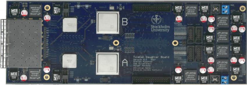
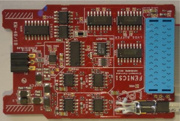
Front-end electronics for TileCal at HL-LHC
 FENICS
 • Fast Readout: two gain amplification for physics;
 • PMT Current Integrating Readout for 137Cs calibration & Luminosity measurements;
 • Integrator Readout has 6 gains to cover 7-8 orders of magnitudes in luminosity;
 • Improved precision and better noise performance than legacy;

 ATL-TILECAL-SLIDE-2020-396
 • Charge injection system for precise calibration.
 Mainboard
 • Fast readout: 24 12-bit ADCs @40 Msps ;
 • Integrator Readout: 12 16-bit SAR ADCs § Routes the digitized data to the Daughter
 Board ;
 • Digital control of the front-end boards (configure for calibration or Physics).

 Daughterboard
 • High Speed communication 4.8/9.6 Gbps;
 • Send detector data to off-detector electronics;
 • Receive, distribute LHC clocks, configurations and control ;
 • 2 FPGAs Kintex Ultrascale (KU);
 • Recent redesign due to single event latch-ups observed in previous FPGA
 (KU+)

Ryan McKenzie DIS2021 7
Coordinate system used in LHC experiments

• The Z axis is oriented along
 the beam pipe;
• The azimuthal angle (φ) is
 defined with respect to the
 x-y plane;
• The pseudorapidity (η) is
 defined to exploit the
 cylindrical geometry.

 Experimental Particle Physics, Understanding the measurements and searches at the Large Hadron Collider, Deepak Kar, School of Physics, University of
 Witwatersrand, Johannesburg, South Africa, ISBN 978-0-7503-2112-9, Pg. 2-10.

Ryan McKenzie DIS2021 7
Map of Tile cells, showing tower structure

 ATLAS-TDR-028, Pg 5
Ryan McKenzie DIS2021 7
Calorimeter response to single isolated charged hadrons
• Characterized by the mean of the energy over momentum
 (E/p) as a function of momentum, integrated over the
 pseudo-rapidity and φ coverage of the calorimeter, as
 measured by the ATLAS Tile Calorimeter using 1.6 fb-1 of
 proton-proton collision data at 13 TeV collected in 2015.
• The fraction of events with additional simultaneous proton-
 proton collisions (pile-up) was negligible. The data is
 compared to simulated events generated using PYTHIA
 8.186, with the A2 tune, and the MSTW2008 LO parton
 distribution function set.
• The energy is reconstructed from topological clusters
 matched to a track in a cone of ΔR < 0.2. Tracks are required
 to pass minimum quality criteria and p > 2 GeV. To reduce
 contamination from neutral hadrons and muons, the energy
 deposited in the electromagnetic calorimeter is required to be
 less than 1 GeV, and the fraction of energy deposited in the
 Tile Calorimeter at least 70%.
• Black dots represent data and the blue line represents
 simulation. Statistical uncertainties are shown for data and
 simulation. The lower plot shows the ratio of data to
 simulation.

Ryan McKenzie DIS2021 7
Tile Calorimeter Cell Energy Deposition Plot

 • Distributions of the energy deposited in the TileCal

 blic/ApprovedPlotsTileEnergyDeposition
 https://twiki.cern.ch/twiki/bin/view/AtlasPu
 cells from collision data at sqrt{s}=13 and 0.9 TeV
 superimposed with Pythia minimum bias Monte
 Carlo and randomly triggered events from filled and
 empty bunch crossings.
 • A Level 1 minimum bias trigger scintillator (MBTS)
 trigger is required for the 13 TeV data.
 • To ensure exactly one interaction has occurred per
 bunch crossing, only events having a single
 reconstructed primary vertex are selected.
 • Each distribution is normalized to unit area.

Ryan McKenzie DIS2021 7
Test-Beam setup • The beams were produced by extracting 400 GeV protons from the Super Proton Synchrotron (SPS) machine. • The primary target made of beryllium, had a length of 300 mm. The produced secondary beams can have energies from 10 to 350 GeV. • A secondary target of 1000 mm of polyethylene (T4)plus an absorber of lead can be placed in the beam to produce tertiary beams; • Bending magnets were used to determine the beam momentum and charge; • The transverse beam profile is monitored by four wire chambers (BC-1 to BC2). Two scintillators (S1/S2), with an active surface of 5 × 5 cm2 , were used in coincidence to trigger the data acquisition (Physics trigger) and to provide the trigger timing. These two detectors were used to reject beam particles interacting upstream of the detectors. The Cherenkov counters (Ch1, Ch2 and Ch3) allowed the beam particle identification. ATLAS-TDR-028, Pg 43 and 44 Fig. Schematic layout of the H8 beam line. The distances of the components of the beam line from the Scanning Table are reported. Ryan McKenzie DIS2021 7
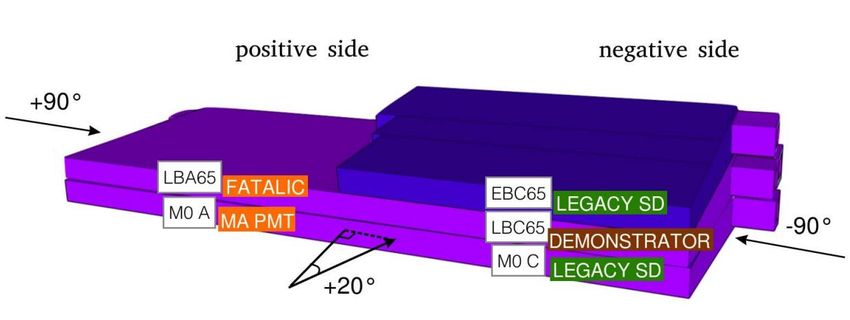
Test-Beam setup
 • The calorimeter setup in the H8 beam of the CERN SPS North Area consists of two long-barrels and one extended-barrel.
 • The super-drawer of the long barrel LBC 65 is equipped with the 3-in-1 front-end upgrade option.
 • The other option, FATALIC, alternative to the 3-in-1 and based on ASICs (An Application Specific Integrated Circuit), has been
 mounted in the super-drawer LBA 65.
 • The super-drawers M0 C and EBC 65 were equipped with the Legacy SD system.
 • Multi-Anode (MA) Photo-Multipliers (PMs) were installed in the M0 A super-drawer.
 • Modules were stacked on a scanning table capable of placing modules at any desired position and angle with respect to the incoming
 particles.
 • Data was collected with beams incident at the center of the front face of each A-cell at θ = 20◦ from the normal and incident on the
 ends of the modules, into the center of each tile-row (referred to as 90◦ incidence).

 ATLAS-TDR-028, Pg 43 and 44
 Fig. Schematic front view of the Tile modules as stacked on the scanning table at the H8 beam.

Ryan McKenzie DIS2021 7
Test-Beam selection criteria
 With all particle beams, two sets of selection criteria were usually applied:

 • For all particle types, single-particle events were selected, using beam detectors upstream of the Tile.

 ATLAS-TDR-028, Pg 43 and 44
 Signals in the upstream scintillator counters were required to arise from single minimum ionizing
 particles. This cut, especially useful for electrons, removed particles that initiated a shower upstream of
 the calorimeter, as well as two-particle events.
 Events where the beam chambers indicated tracks far from the beam axis and/or not parallel to it were
 rejected because they might have scattered upstream and therefore be off-energy;

 • The second set of selection criteria was specific to the type of particles being studied. Particles with
 different energies were identified mainly by the calorimeter response, however, the three beam-line
 Cherenkov counters further assisted in particle identification,

Ryan McKenzie DIS2021 7
Electron data MC comparison

 • The distributions obtained using
 experimental and simulated data in the
 case of beams incident in the A-4 cell at

 TLAS-TDR-028 Pg. 49
 20° are shown.
 • For a given beam energy the experimental
 and the simulated shapes are very similar
 proving the purity of the selected
 experimental electron samples.

 Fig. Distributions of the total energy deposited in the calorimeter obtained using electrons
 beams of 20, 50 and 100 GeV incident in the cell A4 of the middle layer of the stack.

Ryan McKenzie DIS2021 7
Fractional resolutions vs 1 ⁄

 The fractional resolution is defined as : =

 A quantitative comparison between

 ATL-COM-TILECAL-2020-003

 experimental and simulated results is ∆ = − 1
 described as

 The range of ∆ is:

 • Protons - 3 %

 The resolution can be parameterized according to

 = ⊕b

 • a - the stochastic term,
 • b - the cell response non-uniformity,
 • The symbol ⊕ indicates the sum in quadrature.

Ryan McKenzie DIS2021 7
Results with muons: dE/dl VS cell
• The response of the detector has been
 studied determining the ratio between
 the energy deposited in a calorimeter cell
 (dE) and the track path-length in the cell

 ATL-COM-TILECAL-2018-002
 (dl) using 165GeV muons at an incident
 angle of -90°;
• The ratio (R) of experimental and
 simulated dE/dl values was defined for
 each calorimeter cell –

 R =

• The red horizontal lines - the mean values
 of dE/dl for each layer.
• The data show a layer uniformity at 1%. Fig. Ratios of the truncated means of the distributions of the energy deposited in the layer
 An offset of max 4% is observed for cells per unit of path length obtained using 900 experimental and simulated muon data as
 a function of the cell number. The horizontal lines correspond to the mean values of the
 Data/MC. determinations.

Ryan McKenzie DIS2021 7
You can also read