THE INFLUENCE OF GROUND CONTROL POINTS CONFIGURATION AND CAMERA CALIBRATION FOR DTM AND ORTHOMOSAIC GENERATION USING IMAGERY OBTAINED FROM A ...
←
→
Page content transcription
If your browser does not render page correctly, please read the page content below
ISPRS Annals of the Photogrammetry, Remote Sensing and Spatial Information Sciences, Volume V-1-2020, 2020
                                                XXIV ISPRS Congress (2020 edition)

THE INFLUENCE OF GROUND CONTROL POINTS CONFIGURATION AND CAMERA
 CALIBRATION FOR DTM AND ORTHOMOSAIC GENERATION USING IMAGERY
                  OBTAINED FROM A LOW-COST UAV

                                                     M. V. Y. Garcia1, ∗, H. C. Oliveira2
 1
     University of Campinas, Graduate Program in Civil Engineering, 13083-889 Campinas, SP, Brazil- m226741@dac.unicamp.br
     2
      University of Campinas, Dept. of Infrastructure and Environment, 13083-889 Campinas, SP, Brazil - hcandido@unicamp.br

                                                          Commission I, WG I/9

KEY WORDS: Unmanned Aerial Vehicle (UAV), Ground Control Point (GCP), Accuracy Evaluation, Digital Terrain Model
(DTM), Orthomosaic, Photogrammetry

ABSTRACT:

Technological improvement of Unmanned Aerial Vehicles (UAVs) and computer vision algorithms, such as Structured-from-Motion
(SfM) and Multi-view Stereo (MVS) have provided the possibility for high-resolution mapping and high-density point cloud gen-
eration using low-cost equipment and sensors. Orthomosaics and Digital Terrain Model (DTM) are the main digital products
considering mapping purposes. Their quality is directly related to the sensors boarded on the UAV and data processing. Ground
Control Points (GCPs) are used in the process of indirect georeferencing and also to model the lens distortions. The number of
GCPs used in this process affects the positional accuracy of the final products. This study aims to determine the optimum number
of GCPs to achieve high accuracy orthomosaics and DTM. To obtain this optimum number, an area of 3.85 ha was mapped with a
low-cost UAV DJI Phantom 4 Advanced at 31 m flying height, lateral and longitudinal overlap of 90% and 80%, respectively, and
using 22 checkpoints for quality assessment. For the experiments, different configuration were used both for the number of GCPs
and for the use of self-calibration process or pre-calibrated camera IOP (Interior Orientation Parameters). The results show that for
the flight configuration used in this work and for the mentioned UAV, a total of 5 GCPs, with pre-calibrated camera IOP, yields an
accuracy of 0.023 m for X, 0.031 m for Y and 0.033 m for Z.

                         1. INTRODUCTION                                disadvantages of UAVs include the limitation of the payload, re-
                                                                        duced autonomy, dependence on climatic conditions (temperat-
Digital photogrammetric products (mainly digital terrain model          ure, lightning exposure and wind) and low-quality sensors (po-
(DTM) and orthomosaics) are the primarily cartographic out-             sitioning, orientation and imaging sensor) (Chiang et al., 2015)
puts for many applications, such as estimation of cut and fill          - mainly in low-cost platforms. As the sensors are low-costs,
volume (Siebert, Teizer, 2014), highway monitoring and in-              their data are not accurate enough for most of engineering ap-
spection (Patias et al., 2017), infrastructure monitoring (Green-       plications due to their systematic and random errors. The data
wood et al., 2019), dam monitoring (Ridolfi et al., 2017), map-         acquired by these sensors can only be used as initial parameters
ping (Oliveira et al., 2015), erosion monitoring (James et al.,         in the photogrammetric process (Kraus, 2011).
2017), detecting and analyzing pavement distresses (Roberts et
al., 2020), post disaster assessment (Kerle et al., 2020), and oth-     The combination of affordable UAVs and photogrammetric soft-
ers.                                                                    ware makes it possible to create georeferenced models at a much
                                                                        lower cost and faster than through conventional methods (Gerke,
Traditionally, the collection of geospatial data for 3D mapping         2018). Photogrammetric software, such as Metashape, with ro-
is conducted using conventional survey methods by using GNSS            bust computer vision algorithms SfM (Strutuctured from Mo-
(Global Navigation Satellite System) receivers and/ or total sta-       tion) and MVS (Multi-view Stereo)) automated the image match-
tion, and recently, by the usage of RTK (Real Time Kinematics)          ing task and the dense cloud generation (Vosseman et al., 2004).
GNSS technique. These methods are very costly, time consum-
ing, and in some scenarios it is difficult to access the site area.     With the popularization of low-cost UAV platforms, off-the-
UAV Photogrammetry is presented as a flexible and low-cost              shelf digital cameras availability, ease-of-use of automated pho-
option compared to conventional surveying, traditional aerial           togrammetric software together with users deficit knowledge
mapping and orbital imagery (Colomina, Molina, 2014).                   results in products that are visually accepted. However, the
                                                                        products carry errors derived from the lens distortion and errors
The UAV is able to autonomously follow a pre-programmed                 from the navigation parameters. Basically, there are 4 reasons
flight plan, to take-off from a specific point, to fly over a desired   that affect the final results of photogrammetric products: cam-
area to take pictures, and to land in a defined region. Also, there     era calibration, image overlap and flight height, and number
is the possibility to monitor the flight and control the UAV by         of GCP (Ground Control Points). This research aims to study
using a mobile device. All data acquired by the sensors is mon-         the impact of a non-metric digital camera and also find the op-
itored in real time, such as altitude, attitude, aircraft speed, wind   timum number of GCP for high accuracy mapping, considering
speed, battery status and distance from home point. Theses in-          two different camera calibration methods. The statistical ana-
formation are vital to make decisions when flying a UAV. The            lysis is based on the RMSE of check-points and on analyzing if
     ∗ Corresponding   author                                           the population follows a normal distribution.

           This contribution has been peer-reviewed. The double-blind peer-review was conducted on the basis of the full paper.
                       https://doi.org/10.5194/isprs-annals-V-1-2020-239-2020 | © Authors 2020. CC BY 4.0 License.                   239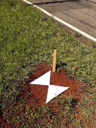
ISPRS Annals of the Photogrammetry, Remote Sensing and Spatial Information Sciences, Volume V-1-2020, 2020
                                              XXIV ISPRS Congress (2020 edition)

       2. RELATED WORK AND BACKGROUND                                  a brief explanation of ground control points and check-points
                                                                       survey. Section 3.3 details the steps to conduct the photogram-
The goal of photogrammetric processing is to derive metric             metric pipeline aiming to generate photogrammetric products at
information from multiples images. There are two main fun-             two different configurations, by using a self-calibration and by
damental prerequisites to derive accurate metric information:          using fixed IOP. Finally, in section 3.4 the products evaluation
camera calibration and image orientation (Förstner et al., 2004).     and statistical analysis are presented.

According to (Galo, Tommaselli, 2011), when applying a non-            3.1   Study Area and UAV Data Acquisition
metric digital camera, it is necessary to carry out a camera cal-
ibration process to extract reliable metric information from a         The study area of approximately 3.85 ha is located near the Fac-
set of 2D images. Usually, off-the-shelf digital cameras express       ulty of Civil Engineering, Architecture and Urban Planning at
two different types of distortion: radial distortion (k1 , k2 , k3 )   the University of Campinas (22.8167◦ S, 47.0604◦ W) (Figure
and tangential distortion (p1 and p2 ) (Brown, 1971). Camera           1), Brazil. This area area covers two parking lots and it has low
calibration is the process of correcting the lens distortion, prin-    vegetation, with the terrain altitude ranging from 626.10 m to
cipal point displacement (xp and yp ) and the focal length (c ).       635.90 m.
Self-calibration is the process in which these parameters are ob-
tained simultaneously with the image orientation (Kraus, 2011).
The final results of a camera calibration is a representation of
the interior camera geometry during image acquisition by mod-
elling the Interior Orientation Parameters (IOP).

To date, there is vast literature aiming to model the impact of
unstable low-cost digital cameras IOPs aiming to reduce the ef-
fort to improve the quality of final products derived from UAV
imagery. These methods rely on different approaches, among
these: different patterns for calibrating the cameras(linear fea-
tures (Zhang, W, 2020) and 2d checkerboard (Zhang, 2000)),
reducing the number of images (Geiger et al., 2012) and the
difference in scale when using a 3D calibration range (Hamid,
Ahmad, 2014). The use of computer vision algorithms reduced
the time to calibrate the camera and produce reliable paramet-
ers, due to the task of measuring control points is automated.

In regards to the use of GCP in aerial imagery, its necessity
is brought due to the use of a low-precision sensors, mainly
integrated GNSS/inertial systems. These both sensors provide
the Exterior Orientation Parameters (EOPs) that represents the
position and attitude of each image at the moment of acquis-
ition. As soon as these parameters are not accurate, the final
product incorporate undesired errors if direct georeferencing is
considered. Therefore, when using low-cost system, it is im-
portant to use the direct EOP as initial values in the photo-
triangulation and adjustment process to reduce the processing
time. The usage of a set of known coordinate points (GCP)
visible from more than one image allow the execution of an
indirect orientation, but only when the overlapping images are
connected via tie-points (Förstner et al., 2004). One of the most
costly and time consuming tasks is to place and measure the
GCP on the field and on the images - the last task has been
                                                                                             Figure 1. Study area
run in a semi-automatic mode in most of photogrammetric soft-
ware. Besides the time consuming field task, there is a pos-
sibility to insert systematic errors when measuring the GCP in         A DJI Phantom 4 Advanced (Figure 2) was used for this study.
object and image space. In literature, there is no expressive          The low-cost UAV weights 1.38 kg and is equipped with GNSS
improvement in accuracy when using more than 7 to 10 GCP               receiver, INS, and a built-in digital camera with a sensor size of
other than reducing the final standard deviation as the number         2.63 µm capable of taking images with a resolution of 20 MP
of GCP increases (Tonkin, Midgley, 2016, Agüera-Vega et al.,          and 4864 × 3648 pixels.
2017, Sanz-Ablanedo et al., 2018). Also, the references recom-
mend positioning the GCP on the external borders and the cen-          The UAV was controlled via radio by a mobile device. The
ter of the site(Agüera-Vega et al., 2017).                            flight planning was done and conducted with DroneDeploy on-
                                                                       line application, choosing a flight configuration of: longitud-
                                                                       inal and lateral overlap of 90% and 80%, respectively, at flying
              3. MATERIAL AND METHODS                                  height of approximately 31 m, and the camera being oriented
                                                                       in a nadiral direction. This configuration provided an aver-
In this section materials will be presented and the proposed           age GSD (Ground Sample Distance) of 0.85 cm. The EOP are
methodology will be discussed. In section 3.1 study area and           stored in the image metadata, also known as external informa-
UAV data acquisition steps are introduced. Section 3.2 gives           tion file (EXIF), as geotags. In total, the mission provided 1336

         This contribution has been peer-reviewed. The double-blind peer-review was conducted on the basis of the full paper.
                     https://doi.org/10.5194/isprs-annals-V-1-2020-239-2020 | © Authors 2020. CC BY 4.0 License.                     240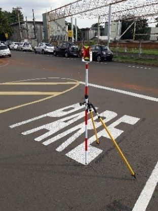
ISPRS Annals of the Photogrammetry, Remote Sensing and Spatial Information Sciences, Volume V-1-2020, 2020
XXIV ISPRS Congress (2020 edition)
for this choice is due to experiments done using different photo-
grammetric software, in which Metashape presented better res-
ults for DTM generation (Ferreira et al., 2019). The processing
steps followed the standard photogrammetric pipeline (Figure
5) aiming to generate 3D point cloud, DEM (Digital Elevation
Model), DTM and orthomosaic. Photogrammetric pipeline will
be conducted under two photo-triangulation configuration using
different number of GCP (0, 3, 4, 5, 8 and 10): first configura-
tion is conducted using self-calibration with GCP coordinates to
Figure 2. DJI Phantom 4 Advanced correct the image orientation and lens distortion, and the second
configuration is inserting the IOP derived from an on-the-job
self-calibration processing using the imagery obtained from the
images and a flight time duration of 46 minutes using 3 batter-
same area and all 32 GCPs.
ies.
In Brazil, the usage of this type of UAVs in urban areas requires
submission and approval of flight configuration (the height and
area to be covered). Therefore, the flight configuration for this
research was submitted and approved by the ANAC (National
Civil Aviation Agency - Brazil).
3.2 Ground Control Points and Check Points
Before proceeding with the imagery acquisition, a set of 32
points were established. To survey these points, 3 landmarks
were established and surveyed using GNSS receivers/antenna
Topcon Hyper/Hyper Lite+ in static mode (adjusted coordin-
ates with standard deviation of 1.0 cm and 2.0 cm, in planimet-
ric and altimetric components, respectively). The total station
Nikon Nivo 5C was used to collect all 32 points for the experi-
ments - to be used as GCP and check-points (standard deviation
of 0.6 cm and 0.8 cm, in planimetric and altimetric compon-
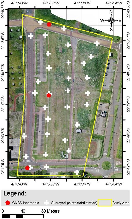
ents, respectively). The points were materialized using a sheet
of white paper attached to the ground with long nails. The tar-
get final dimensions were 0.70 m × 0.70 m (Figure 3a). To
reduce the labor, established features such as signing and pave-
ment marking were also used (Figure 3b).
Figure 5. Standard photogrammetric pipeline
The first step is to align images using an algorithm similar to
the Scale Invariant Feature Transform (SIFT) operator (Lowe,
2004) to identify and match relevant points in all images, also
(a) (b) known as keypoints. These keypoints are well defined and in-
variant to image scale and rotation. In this step, the geolocation
Figure 3. GCP and Check-point. a) Target using white paper stored in the EXIF is used as initial approximation to minimize
sheet; b) Signing and pavement marking. the processing time. The second step is to import and manually
measure the points that are going to be used as GCP.
Some of these points were applied as GCP in the process of
aerial triangulation, ranging from 0 to 10 points, and from 22 to The third step is to optimize the EOP and IOP. In this step,
32 points used as check points, according to each configuration photo-triangulation is performed using GCP coordinates to cor-
tested (Figure 4). rect the image orientation, and also to calibrate the camera (if
desired). In the case where the camera is pre-calibrated, there
3.3 Photogrammetric Processing, Point Cloud Classifica- is no need to perform the ”optimize parameters” step since the
tion and DTM Generation IOP are already optimized and the indirect orientation was done
in the ”alignment” step. Fixed IOP is derived from an on-the-
In regards to the capacity of computational processing and to job self-calibration using all 32 points, which aimed to determ-
ensure consistent results, all tasks were performed using the ine the following parameters: focal length, principal point dis-
same computer. Photogrammetric processing was conducted placement (xp and yp), radial distortion (k1, k2, and k3) and
in Agisoft Metashape, version 1.5.5 (LLC, 2018). The reason decentering distortion (p1 and p2).
This contribution has been peer-reviewed. The double-blind peer-review was conducted on the basis of the full paper.
https://doi.org/10.5194/isprs-annals-V-1-2020-239-2020 | © Authors 2020. CC BY 4.0 License. 241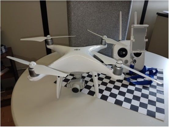
ISPRS Annals of the Photogrammetry, Remote Sensing and Spatial Information Sciences, Volume V-1-2020, 2020
                                             XXIV ISPRS Congress (2020 edition)

                                                    Figure 4. GCP configuration

The fourth step is the dense cloud generation. This task ap-         where        n = number of CP tested
plies a pair-wise depth map computation to generate 3D point                      Xi = X, Y or Z coordinates measured in the
cloud. Finally, the DEM reconstruction task is used to generate                   cartographic product for the ith CP
the input for georeferenced orthomosaic. The configurations
for image alignment and dense cloud generation was set to me-        If a sample is extracted from a population, it it necessary to
dium and the orthomosaics were exported with 2.0 cm resolu-          assess for significance using a two-tail t-test. In this case, a 90%
tion (2.35 × average GSD).                                           confidence level was considered, according to (Galo, Camargo,
                                                                     1994). First, discrepancies are calculated (Equation 2) for each
For the DTM generation, the generated 3D LAS point cloud
                                                                     component. The second step is to calculate the mean (Equation
was imported to the Trimble TBC software (Trimble, 2018).
                                                                     3) and the standard deviation (Equation 4).
First, a classification and filter tool was used to extract only
points representing the ground level. The second and last step
is to create a surface from the extracted ground points. This                                ∆X = (Xi − Xir )                         (2)
interpolated surface will be used to extract the Z component for
each surveyed point aiming to evaluate the DTM quality.
                                                                                                        n
In total, 12 independent photogrammetric processing were per-                                         1X
                                                                                            ∆X̄ =         ∆Xi                         (3)
formed, using 0, 3, 4, 5, 8 and 10 GCP, and the remaining points                                      n
                                                                                                        i=1
were used as check points.
                                                                                          v
3.4   Products Evaluation and Statistical Analysis                                        u        n
                                                                                          u     1 X
                                                                                   S∆X   =t          (∆Xi − ∆X̄)2                     (4)
The input information for the planimetric evaluation of the fi-                                n−1
                                                                                                       i=1
nal orthomosaics was obtained by using QGIS 3.8.2 software
(QGIS Development Team, 2018). A point shapefile layer (.shp)
was created and points were measured on centres of established       In this step, it is necessary to calculate t (Equation 5) and test it
marks and pavement signs. Resulting shapefile layer was ex-          against the confidence interval (Equation 6).
ported as text file with the following information: point ID, X
and Y coordinates.                                                                                    ∆X̄ √
                                                                                               tx =        n                          (5)
                                                                                                      S∆X̄
The input data for DTM evaluation was obtained by using Trim-
ble TBC software. The X and Y coordinates of check-points
were imported as points and the Z coordinates were extracted                                  |tx | < tn−1,α/2                        (6)
from the interpolated surface. The resulting report was exported
as text file with the following information: point ID, X, Y and
Z (interpolated) coordinates.                                        The population is accepted if t-calculated is lower than t-critical.
                                                                     This hypothesis suggests that the population presents a normal
All the extracted coordinates were then compared to the sur-         distribution.
veyed check-points coordinates.
                                                                                   4. RESULTS AND DISCUSSION
For both planimetric and altimetric evaluation the Root Mean
Square Error (RMSE) considering surveyed and measured in
                                                                     The aim of this study is to investigate the impact of the number
final products was used. This metric measures the discrepancies
                                                                     of GCPs on photo-triangulation process and the usage of fixed
between the reference coordinates and the extracted coordinates
                                                                     IOP vs. self-calibration. The results provide an optimum num-
from orthoimages and DTM (Ghilani, Wolf, 2006). Calculation
                                                                     ber of GCP based on accuracy results for a light weight-rotatory
of RMSE in regards to a given component X, Y or Z in a sample
                                                                     wing UAV when generating orthomosaic and DTM products.
size (n) is presented in Equation 1.
                                                                     The results and discussion session is focused on RMSE and
              v                                                      population distribution. Based on the study, two sets of out-
              u
              u1 Xn                                                  put are obtained. The first result is for orthomosaic (planial-
      RM SE = t     (XRef erence − XComputed )2              (1)     timetric evaluation) and the second for DTM (altimetric eval-
                n                                                    uation). For the proposed method, a comparison is presented
                        i=1

         This contribution has been peer-reviewed. The double-blind peer-review was conducted on the basis of the full paper.
                     https://doi.org/10.5194/isprs-annals-V-1-2020-239-2020 | © Authors 2020. CC BY 4.0 License.                      242
ISPRS Annals of the Photogrammetry, Remote Sensing and Spatial Information Sciences, Volume V-1-2020, 2020
XXIV ISPRS Congress (2020 edition)
in Table 1 (self-calibration) and 2 (fixed IOP), with the follow- 4.2 Digital Terrain Model (Altimetric Evaluation)
ing information: GCP is the number of ground control points
used, CP is the number of check-points used, RMSE measured Table 1 and 2 show the errors obtained from the DTM. The
in meters for each component (X, Y and Z), µ is the median processing using 0 GCP has a RMSE of 10.214 m using self-
in meters, σ is the standard deviation in meters, and B (Y for calibration and 10.104 m using fixed IOP. As noticed on the or-
biased and N for unbiased results). Values presented in paren- thomosaic analysis, the errors are due to the low-quality sensors.
thesis are negative. Following the same processing using as the centimeter level ac-
curacy for the orthomosaic (3 GCP), the DTM reached 0.441
GCP 0 3 4 5 8 10 m and 0.039 m, for self-calibration and fixed IOP, respectively.
CP 32 29 28 27 24 22 It is noticed that the optimum number for generating accurate
X 0.464 0.038 0.030 0.024 0.026 0.024 DTM is 8 GCP using self-calibration (0.052 m) and 5 GCP us-
µ (0.438) (0.020) (0.013) (0.007) (0.005) 0.001 ing fixed IOP (0.33 m).
σ 0.155 0.033 0.027 0.023 0.026 0.025
B Y Y Y N N N
5. CONCLUSION
Y 2.180 0.042 0.037 0.032 0.032 0.029
µ 2.178 0.018 (0.008) 0.005 0.006 0.002 This paper presented a positional evaluation of generated DTM
σ 0.090 0.039 0.037 0.032 0.032 0.030 and orthomosaic based on UAV images acquired with a low-
B Y Y N N N N cost UAV DJI Phantom 4 Advanced. Overall, the results ob-
Z 10.214 0.441 0.399 0.052 0.029 0.034 tained from 12 sets of photogrammetric processing were com-
µ (10.070) (0.387) (0.366) (0.033) 0.004 0.005 pared to the reference coordinates acquired by traditional sur-
σ 1.735 0.216 0.161 0.040 0.030 0.034 vey methods. The authors also determined the optimum number
B Y Y Y Y N N of GCPs by processing with self-calibration and fixed IOP with
0, 3, 4, 5, 8 and 10 GCP.
Table 1. Statistics of photo-triangulation with self-calibration
The results show that there are no expressive precision improve-
GCP 0 3 4 5 8 10 ments on orthomosaics by using more than 3 GCPs to reach a
CP 32 29 28 27 24 22 centimeter level accuracy when using self-calibration or fixed
X 0.461 0.036 0.030 0.023 0.025 0.024 IOP. In regards to the DTM, when applying self-calibration ap-
µ (0.444) (0.027) (0.019) (0.007) (0.005) (0.002) proach and using 5 GCP (4 on the external borders and the cen-
σ 0.126 0.025 0.024 0.023 0.025 0.024 ter of the site), a centimeter level accuracy is reached (0.052
B Y Y Y N N N m).
Y 2.187 0.030 0.033 0.031 0.031 0.030
µ 2.177 (0.002) (0.007) 0.004 0.006 0.003 Overall, the results are quite similar in both scenarios. The op-
σ 0.212 0.030 0.033 0.032 0.031 0.031 timum number of GCP to produce a high accuracy orthomosaic
B Y N N N N N and DTM when processing with self-calibration is 8 GCP to
achieve accuracy of 0.026 m and 0.032 m, and 0.029, for X, Y
Z 10.104 0.039 0.037 0.033 0.034 0.029
and Z, respectively. On the other hand, applying a fixed IOP
µ (9.961) (0.024) (0.012) (0.002) 0.002 0.007
σ 1.722 0.032 0.036 0.034 0.035 0.029 using 5 GCP reduces the labor and generates unbiased results
B Y Y Y N N N with an accuracy of 0.023 m, 0.031 m and 0.033 m, for X, Y
and z, respectively.
Table 2. Statistics of photo-triangulation with fixed IOP From practical point of view, placing more GCP makes the sur-
vey more labor intensive and expensive. However, these ele-
The results presented in Table 1 and 2 are used for discussion
ments allow the production of better quality products. It is im-
in the following sessions.
portant to mention that this methodology may not have same
results when using different equipments over a really different
4.1 Orthomosaic (Planimetric Evaluation) area characteristics as those presented in this research, and also
running the different flight configuration. Even though, the res-
In terms of accuracy, increasing the number of GCP with reg- ults can be used to have an idea of the importance of using GCPs
ular spatial distribution indeed increases the accuracy. As ob- in processing dataset from low-cost UAV. For future work, the
served when using no GCP, the X coordinates are 0.464 m and image overlap and flight height will be addressed to obtain an
0.361 m, the Y coordinates are 2.180 m and 2.187 m, with self- optimum flight configuration.
calibration and with fixed IOP respectively. These errors are
due to the information derived from the low quality sensors on-
board. As the processing only had the data stored in the EXIF ACKNOWLEDGEMENTS
file, there is no accurate information to properly reference, ro-
tate, translate and scale the model. The researchers would like to thank the Graduate Program in
Civil Engineering (PPGEC) at University of Campinas (UNI-
The processing with 3 GCP reached a cm level accuracy, match- CAMP) for the facility and equipments, and the UNICAMP
ing the requisites to indirect georefence a model (Kraus, 2011). Support Fund for Education, Research and Extension (FAE-
Besides the accuracy, a digital product can only be reliable if PEX), grant number 2859/18 given to the first author.
the population follows a normal distribution. This scenario is
accepted when the self-calibration processing is conducted us- REFERENCES
ing 8 GCP, and also when using 5 GCP with fixed IOP. It is
important to mention that adding more than 3 GCP to the pro- Agüera-Vega, F., Carvajal-Ramı́rez, F., Martı́nez-Carricondo,
cessing only reduces the check-points standard deviation. P., 2017. Assessment of photogrammetric mapping accur-
This contribution has been peer-reviewed. The double-blind peer-review was conducted on the basis of the full paper.
https://doi.org/10.5194/isprs-annals-V-1-2020-239-2020 | © Authors 2020. CC BY 4.0 License. 243ISPRS Annals of the Photogrammetry, Remote Sensing and Spatial Information Sciences, Volume V-1-2020, 2020
XXIV ISPRS Congress (2020 edition)
acy based on variation ground control points number us- Kraus, K., 2011. Photogrammetry – Geometry from images and
ing unmanned aerial vehicle. Measurement: Journal of laser scans. 2nd ed. Walter de Gruyter, Berlin.
the International Measurement Confederation, 98, 221–227.
doi.org/10.1016/j.measurement.2016.12.002. LLC, A., 2018. Agisoft metashape pro. Agisoft LLC, St. Peters-
burg, Russia, Version 1.5.5, build 9097.
Brown, D. C., 1971. Close-range camera calibration. Photo-
gramm. Eng, 37(8), 855–866. Lowe, D. G., 2004. Distinctive image features from scale-
invariant keypoints. International journal of computer vision,
Chiang, K. W., Tsai, M. L.and Naser, E. S., Habib, A., Chu, 60(2), 91–110. doi.org/10.1023/B:VISI.0000029664.99615.94.
C. H., 2015. A New calibration method using low cost MEM
IMUs to verify the performance of UAV-borne MMS payloads. Oliveira, H. C., Galo, M., Dal Poz, A. P., 2015. Height-gradient-
Sensors (Switzerland), 15(3), 6560–6585. based method for occlusion detection in true orthophoto gener-
ation. IEEE Geoscience and Remote Sensing Letters, 12(11),
Colomina, I., Molina, P., 2014. Unmanned aerial systems 2222–2226. doi.org/10.1109/LGRS.2015.2459671.
for photogrammetry and remote sensing: A review. ISPRS
Journal of photogrammetry and remote sensing, 92, 79–97. Patias, P., Giagkas, F., Georgiadis, C., Mallinis, G., Kaimaris,
doi.org/10.1016/j.isprsjprs.2014.02.013. D., Tsioukas, V., 2017. Evaluating horizontal positional ac-
curacy of low-cost uav orthomosaics over forest terrain using
Ferreira, A. A. C., Garcia, M. V. Y., Oliveira, H. C. O., 2019. ground control points extracted from different sources. Fifth In-
Avaliação da qualidade altimétrica de modelos digitais de ter- ternational Conference on Remote Sensing and Geoinformation
reno derivados de levantamento topográfico com vant. XIX of the Environment (RSCy2017), 10444, International Society
Simpósio Brasileiro de Sensoriamento Remoto, Anais do XIX for Optics and Photonics, 104440U.
Simpósio Brasileiro de Sensoriamento Remoto, 41–48.
QGIS Development Team, 2018. Qgis geographic information
Förstner, W., Wrobel, B., Paderes, F., Craig, R., Fraser, C., Dol- system. Open Source Geospatial Foundation, Version 3.8.2.
loff, J., 2004. Analytical photogrammetric operations. E. M.
McGLONE, J. C., J. BETHEL (eds), Manual of photogram- Ridolfi, E., Buffi, G., Venturi, S., Manciola, P., 2017. Accuracy
metry. 5th ed., American Society for Photogrammetry and Re- analysis of a dam model from drone surveys. Sensors (Switzer-
mote Sensing, Bethesda, Maryland, chapter 11, 763–936. land), 17(8), 1777. doi.org/10.3390/s17081777.
Galo, M., Camargo, P. D. O., 1994. O uso do gps no controle Roberts, R., Inzerillo, L., Di Mino, G., 2020. Exploit-
de qualidade de cartas. 1◦ Congresso Brasileiro de Cadastro ing Low-Cost 3D Imagery for the Purposes of Detecting
Técnico Multifinalitário, II, 41–48. and Analyzing Pavement Distresses. Infrastructures, 5(1), 6.
doi.org/doi.org/10.3390/infrastructures5010006.
Galo, M., Tommaselli, A. M. G., 2011. Calibração de câmaras.
J. C. Rodrigues, R. R. Nelson (eds), Fundamentos de Visão Sanz-Ablanedo, E., Chandler, J. H., Rodrı́guez-Pérez, J. R.,
Computacional, São Paulo State University, Faculty of Science Ordóñez, C., 2018. Accuracy of unmanned aerial vehicle (UAV)
and Technology Press, Presidente Prudente, chapter 2, 53–112. and SfM photogrammetry survey as a function of the number
and location of ground control points used. Remote Sensing,
Geiger, A., Moosmann, F., Omer, C., Schuster, B., 2012. Auto- 10(10), 1606. doi.org/10.3390/rs10101606.
matic camera and range sensor calibration using a single shot.
International Conference on Robotics and Automation (ICRA), Siebert, S., Teizer, J., 2014. Mobile 3D mapping for
3936–3943. surveying earthwork projects using an Unmanned Aerial
Vehicle (UAV) system. Automation in construction, 41, 1–14.
Gerke, M., 2018. Developments in UAV-Photogrammetry. doi.org/10.1016/j.autcon.2014.01.004.
Journal of Digital Landscape Architecture, 47–56.
Tonkin, T. N., Midgley, N. G., 2016. Ground-control net-
Ghilani, C. D., Wolf, P. R., 2006. Photogrammetric Computer works for image based surface reconstruction: An investiga-
Vision. John Wiley Sons, Inc., Hoboken, NJ. tion of optimum survey designs using UAV derived imagery and
Greenwood, W. W., Lynch, J. P., Zekkos, D., 2019. Applica- structure-from-motion photogrammetry. Remote Sensing, 8(9),
tions of UAVs in civil infrastructure. Journal of Infrastructure 786. doi.org/10.3390/rs8090786.
Systems, 25(2), 04019002. doi.org/10.1061/(ASCE)IS.1943-
Trimble, 2018. Trimble business center. Trimble Business Cen-
555X.0000464.
ter, Version 5.10.
Hamid, N. A., Ahmad, A., 2014. Calibration of high resolu-
Vosseman, G., Sester, M., Helmut, M., 2004. Basic com-
tion digital camera based on different photogrammetric meth-
puter vision techniques. E. M. McGLONE, J. C., J. BETHEL
ods. IOP Conference Series: Earth and Environmental Science,
(eds), Manual of photogrammetry. 5th ed., American Society
18, 012030.
for Photogrammetry and Remote Sensing, Bethesda, Maryland,
James, M. R., Robson, S., Smith, M. W., 2017. 3-D uncertainty- chapter 6, 455–499.
based topographic change detection with structure-from-motion
Zhang, L., W, D., 2020. Camera self-calibration using linear
photogrammetry: precision maps for ground control and dir-
features from targets. Eleventh International Conference on
ectly georeferenced surveys. Earth Surface Processes and
Graphics and Image Processing (ICGIP 2019), 11373, Inter-
Landforms, 42(12), 1769–1788.
national Society for Optics and Photonics, SPIE, 249 – 253.
Kerle, N., Nex, F., Gerke, M., Duarte, D., Vetrivel, A.,
Zhang, Z., 2000. A flexible new technique for camera calibra-
2020. UAV-Based Structural Damage Mapping: A Review.
tion. IEEE Transactions on Pattern Analysis and Machine In-
ISPRS International Journal of Geo-Information, 9(1), 14.
telligence, 22(11), 1330—1334. doi.org/10.1109/34.888718.
doi.org/10.3390/ijgi9010014.
This contribution has been peer-reviewed. The double-blind peer-review was conducted on the basis of the full paper.
https://doi.org/10.5194/isprs-annals-V-1-2020-239-2020 | © Authors 2020. CC BY 4.0 License. 244You can also read