The switching control strategy of redundant electromechanical servo system based on the compound sliding mode control
←
→
Page content transcription
If your browser does not render page correctly, please read the page content below
E3S Web of Conferences 268, 01069 (2021)                                 https://doi.org/10.1051/e3sconf/202126801069
VESEP2020

      The switching control strategy of redundant
      electromechanical servo system based on the
      compound sliding mode control
      Zonglun Li *, Zhiyuan Yu, and Menglong Jiang
      Laboratory of Aerospace Servo Actuation and Transmission,Beijing 100076, China

                    Keywords: sliding mode control, redundancy, active-active mode.

                    Abstract. Aiming to resolve the limitations of robustness and stability in
                    switching working modes of dual redundancy electric servo system, a
                    control strategy based on sliding mode control is suggested. By analyzing
                    the electromechanical servo system's basic structure and working theory, a
                    mathematical model is created to enable the design of new control
                    functions. Taking into account the influence of the internal parameter
                    perturbation of the electromechanical servo system during the switching
                    between working modes, the sliding mode control is used to enhance
                    system robustness, and the method of combining the latest saturation
                    function and the exponential reaching law is used to minimize the system
                    chattering. The simulation results and analysis show that the control
                    strategy can effectively improve the robustness and control accuracy of the
                    system.

      1 Introduction
          In the past decade, redundant technology has become a key technology for the
      aerospace sector because of its high reliability. Among the solutions identified for the
      redundancy electromechanical servo system, the dual-motor differential electromechanical
      servo system has a promising future and important significance[1-2]. Compared with
      single-channel servos, the dual-channel design consists of two motors which in the
      active-active working mode can effectively use resources, meanwhile, the redundant design
      greatly improves the reliability of the system. However, when a fault occurs and the
      operating mode needs to be switched, the rotary inertia and other parameters of the system
      change significantly, which requires the system to have fast response performance, better
      response accuracy, and strong robustness.
          Sliding mode control is a device that uses discontinuous control which is different from
      PID and other existing control strategies[3-4]. With the sliding mode configuration, the
      device is insensitive to the change in the control parameters and has tremendous robustness.
      Hence, its use in electronic servo systems is noteworthy. However, sliding mode variable
      structure control triggers system chattering, and researchers have suggested some solutions:

      *   Corresponding author: 18686800261@163.com

© The Authors, published by EDP Sciences. This is an open access article distributed under the terms of the Creative Commons
Attribution License 4.0 (http://creativecommons.org/licenses/by/4.0/).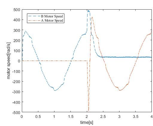
E3S Web of Conferences 268, 01069 (2021)                            https://doi.org/10.1051/e3sconf/202126801069
VESEP2020

      based on a reaching rule method[5-7], boundary layer method[8], terminal sliding
      mode[9-11], sliding mode-predictive control method[12], sliding mode-fuzzy control[13],
      high-order sliding mode method[14-16], etc. and how to suppress chattering has long been
      a research hotspot in related fields.
           In this paper, the sliding-mode variable structure control is applied to a dual-motor
      differential electromechanical servo system to boost responses and facilitate homogeneity.
      The speed loop developed using the combination of the exponential reaching law, and a
      new saturation function, which is effective at suppressing chatter. In addition to the
      traditional PID control technique, an air rudder deflection output and motor speed curve
      were evaluated and the overshoot was decreased, the response time was quicker, and the
      system was more robust. The verification of results confirms the validity of the study and
      its results.

      2 Mathematical model of the electromechanical servo system
      The dual-motor differential electromechanical actuator consists of two permanent magnet
      synchronous motors, NGW planetary reducer, and a ball screw mechanism. The schematic
      diagram of the servo system is shown in Figure 1.

                                             Brake   Motor
                                   Planet     A       A
                                  differen                                       Air
                                                     Ball screw
                                    -tial                                       Vane
                                 mechanism   Brake   Motor
                                               B      B

      Fig. 1. The schematic diagram of the servo system.

      2.1 Modeling of permanent magnet synchronous motors
      First, hypothesize that a permanent magnet synchronous motor would act as a model for an
      ideal electric motor.
          1) The stator windings are uniform and symmetric with no turns; 2) The air gap
      magnetic field is a normal sinusoidal distribution; 3) The eddy current losses and magnetic
      saturation in the iron core are ignored; 4) The rotor has no damping effect, and the
      magnetic connection amplitude is constant[17]. The equation for the magnetic field of the
      permanent magnet stepper motor is as follows:
          For surface-mounted permanent magnet synchronous motors:

                                                             �               dλd
                                                             �ud = R ⋅ id + dt − ωe ⋅ λq
                                                             �               dλq
                                                             � uq = R ⋅ iq +     + ωe ⋅ λ q
                                                             �                dt                       (1)

      where λd= Ldid+ψd, λq= Lqiq+ψq are the total flux of d and q axis respectively; ψd, ψq are the
      flux of d and q axis’s permanent magnet;ud, uq, id, iq are the voltage and current of motor
      stator respectively; R is the resistance of stator winding; Ld, Lq are the inductance of d and q
      aixs.
          The rotor mechanical motion equation of the permanent magnet synchronous motor is
      as follows:

                                                       2
E3S Web of Conferences 268, 01069 (2021)                           https://doi.org/10.1051/e3sconf/202126801069
VESEP2020

                                                                                dω m
                                                                            J        = T e − T d − B ⋅ ωm
                                                                                 dt                       (2)

     where ωm is the mechanical angular velocity; J is the rotary inertia; Te is the
     electromagnetic torque; Td is the load torque; B is the friction factor.
         Permanent magnet synchronous motor rotor electromagnetic torque equation:
                       3                         3
                Te =     pn(λd ⋅ iq − λq ⋅ id ) = pn(ψd ⋅ iq + (Ld − Lq ) ⋅ id ⋅ iq ) = Kt ⋅ iq           (3)
                       2                         2
     where Kt is the motor torque constant;pn is the logarithmic magnetic pole of the rotor.

     2.2 Modeling of the mechanical transmission mechanism

     The mechanisms of the dual-motor differential electromechanical servo system are
     composed of motor, NGW reducer, and ball screw. The motor generates torque, and the
     planetary reducer couples it with the ball screw shaft, then the screw shaft translates the
     torque into axial force to drive the air rudder load. By modifying the voltage supplied to the
     motor and using the electromechanical servo system, you can accurately monitor the
     amount of force and speed needed.
         The mathematical model of how a dual-motor differential electromechanical servo
     device operates gives us the equation for the system.
         1) NGW type planetary reducer
         To minimize power consumption, the NGW style planetary reduction gear was selected
     for the double redundancy electromechanical servo system. The arrangement of the reducer
     is shown in Figure 3. The sun gear and planet carrier are coupled to the A channel, and the
     ring gear and drive gear are coupled to the B channel.
                                                       ωH
                                                   H              ω2            ω34
                                                             H          2
                                           2
                                           1                      ω1
                                                              1         3
                                           3
                                                                                4
                                               4

                                               5             ω5
                                                                    5

                                               6
                                                            ω6          6

     Fig. 2. NGW type planetary reducer.
         According to the various working modes of the device, the reducer is divided into three
     working states: A channel and B channel dual input, A channel single input (sun gear side
     input), and B channel single input (ring gear side input). The dual input ratio is 2.5 and the
     single input ratio is 5. The set consists of T1 and T6, the two input torques, and TH, the load
     torque. The speed of the reducer is obtained by using the equation:
         ①Two channel dual input:

                                                       3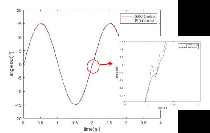
E3S Web of Conferences 268, 01069 (2021)                             https://doi.org/10.1051/e3sconf/202126801069
VESEP2020

                                                                        1     1
                                                                  TH = − T 1 − T 6 + b1ε 1 + b 2ε 2
                                                                        5     5                     (4)

         ②One channel single input(ring gear side input):

                                                                                       1
                                                                                 TH = − T 6 + b 24ε 6
                                                                                       5              (5)

         ③One channel single input(sun gear side input)

                                                                                        1
                                                                                  TH = − T 1 + b 23ε 1
                                                                                        5              (6)

      where b,   ε   are the scale coefficient of interia and accelerated speed.
           2)            Ball screw model:

                                    mbsxema = FG − Ff − Fema                                          (7)

      where mbs is the mass of the ball screw; FG is the load capacity between ball
      bearing and screw; Ff is the friction force; Fema is the external force of the
      EMA.
                                                        2π
                                FG = TGitribs = TGitr                                                   (8)
                                                        pbs
      where TG is output torque of motor; itr ibs are reduction ratio of reducer and ball screw; pbs is
      the helical pitch of ball screw.
          Assuming that all collisions of the electromechanical actuator are completed in an
      instant, the dead zone theory is introduced to simulate the existence of the gap in the hinge
      of the actuator. The x0 represents the total gap while the xm,xl are displacements of the ball
      screw driven by motor and load.

                                     �ks ⋅ (xm − xl − x 0 ) xm − xl > x 0
                                     �
                                FG = �         0            xm − xl = x 0                               (9)
                                     � ks (xm − xl + x 0 ) xm − xl < − x 0
                                     �
           3)             Air vane model

                     mcsxcs = Fema − Fair = ccs (xema − xcs ) + dcs (xema− xcs ) − Fair            (10)

      where mcs,xcs are the mass and displacement of the air vane; Fair is the aerodynamic load
      acting on the rudder surface; ccs,dcs are stiffness coefficient and viscous damping coefficient
      of the air vane.

                                                          4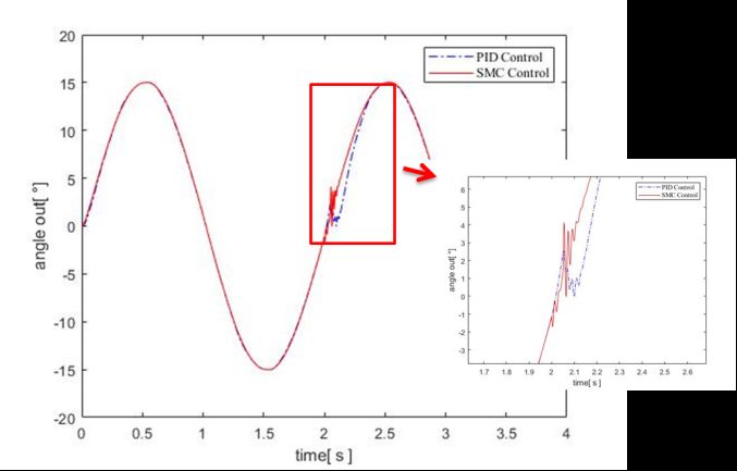
E3S Web of Conferences 268, 01069 (2021)                                https://doi.org/10.1051/e3sconf/202126801069
VESEP2020

     3 Speed loop sliding mode controller design
     Traditional PI control is sensitive to parameter changes and has a poor dynamic response,
     which cannot meet the requirements of high-performance servo systems. Sliding mode
     control is a variable structure control[22]. Due to its strong robustness and irrelevance to
     system parameter changes, it has become a research hotspot in motor control controller
     design in recent years. This paper focuses on the stability issue of the dual-motor
     differential electromechanical servo system during the switching of operating modes, and
     thus introduces speed loop sliding mode control using PID three-loop control. However,
     sliding mode control also brings in the uncooperative condition of unpredictable noise
     production. The sliding mode controller is replaced with an arctangent feature, reducing the
     chattering caused by the controller's motion.
         The concept and implementation of a sliding mode controller for exponentially rising
     speed are as follows.

                                                      e = x′d − x′                                       (11)

        As the actual current iq=x’, set the predicted current value iqd=x’d, then the error
     equation is:

                                                      e = x′d − x′                                    (12)

        Designing of sliding mode surface:

                                                   s = e + c ⋅ ∫ edt                                     (13)

        Set c>0, ε is the constant-velocity reaching law coefficient,k is exponential reaching
     law coefficient, the design of reaching law is given by:

                                          s = −ε ⋅ sign( s ) − k ⋅ s                                    (14)

        Combine equation(2)and the derivation of equantion(14):

                                                  Kt      TL B
                e = ω ref − ω m = ω ref − (      i q − − ωm )                                        (15)
                                                  J       J J
        Refers to equation(14) we can get the output of the speed-loop controller:

                    J �         TL B                                  �
            iq* =      �ω ref +   + ωm + c ⋅ e + ε ⋅ sign(s ) + k ⋅ s �
                    Kt �        J J                                   �                                  (16)
         Via mathematical analysis, the increase of c and k will boost the response of the control
     system and minimize the tracking error, and the decrease of ε will slow down the chattering,
     but it will also cause the system to slow down the tracking speed. ε·sign(s)is the item that
     causes the chattering of the control quantity. The existence of this switching function is the
     key to the advantage that it can ignore the change of the control parameter. Many
     researchers are trying to design tons of sat(s) to replace the sign(s)[18-21]. In this paper, the
     arctangent function: sat(s)=arctan (c0·s) is used in place of the sign function because of its
     simpler properties and fewer parameter choices. The arctangent function curve is smoother
     and more distinct, and the essence of reducing chattering is that multiplying with ε changes
     the benefit of the constant velocity approaching law. When the value of sliding mode

                                                           5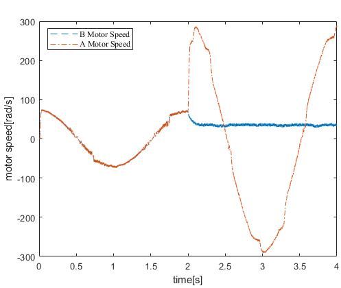
E3S Web of Conferences 268, 01069 (2021)                            https://doi.org/10.1051/e3sconf/202126801069
VESEP2020

      surface s is large, the system gain is a large setting value When approaching the sliding
      mode surface, the system gain decreases as the saturation function value becomes smaller.
      This design not only retains the sliding rate close to the sliding mode surface but also
      reduces the fluctuation of the control amount of the sliding phase. The structure is simple
      which facilitates the development of the engineering design.
          Define the Lyapunov stability equation

                                                   1 2
                                              V=     s                                                (17)
                                                   2
         The derivation of equation(17) is:

           V = s ⋅ s = s(− ε ⋅ arctan(c 0 ⋅ s ) − k ⋅ s ) = − s ⋅ ε ⋅ arctan(c 0 ⋅ s ) − k ⋅ s 2    (18)

      where arctan function is odd, when k > 0 , c 0 > 0 , ε > 0 , V = s ⋅ s < 0 ,
         So the control law is progressively stable in the Lyapunov sense, which is global
      convergence.
         Finally, we can obtain the output of the sliding mode controller is:

                    J �       TL B                                         �
            iq* =      �ωref + + ωm + c ⋅ e + ε ⋅ arctan(c 0 ⋅ s ) + k ⋅ s �                          (19)
                    Kt �      J J                                          �

      4 Simulation results and analysis
      By establishing a dual-motor differential electromechanical servo system model in
      MATLAB/SIMULINK, as shown in Figure 3. The values of some of the simulation's
      vector parameters are shown in Table 1.
                               Table 1. Value of variable in the simulation model.

                    No.            Variable                               Value
                     1                Lm                                0.0018H
                     2                Rm                                  0.15Ω
                     3                Kt                               0.37Nm/A
                     4             BA = BB                                0.004
                     5            K A = KB                           3×10⁵ Nm/rad
                     9                BL                                  0.005
                     10               KL                              2.54×10⁷N/m
                     11               Tf                                4000Nˑm

                                                         6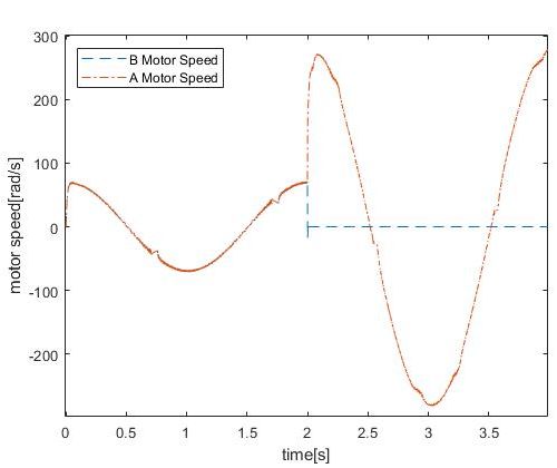
E3S Web of Conferences 268, 01069 (2021)                            https://doi.org/10.1051/e3sconf/202126801069
VESEP2020

     Fig. 3. electromechanical servo system model.

     4.1 Application of arctangent function.

     Based on the above simulation model, a single-channel mode is adopted, the speed loop
     sliding mode controller is selected, the step response is input, and the simulation
     verification is performed. The speed curve using the switching function is shown in the
     figure, and the speed curve using the arctangent function is shown in figure 4.

     Fig. 4. Sign function’s speed curve (left)and the arctangent function’s speed curve(right).
         From Figures 4 and 5, it can be seen intuitively that the speed fluctuation in the output
     of the sliding mode controller by the traditional exponential sliders is greater than the speed
     fluctuation in the output of the improved sliders. When the system reaches the vicinity of
     the sliding mode surface When near the sliding mode surface, the law of reaching the sign
     function is the law of reaching the switching function, and the value of the s function shifts
     rapidly, passing back and forth near the critical point of the s function. The controller of the
     new design type can smoothly reduce the approach gain due to the multiplication of the
     original constant approach rate with the smoothly decreasing arctangent function at the time
     when the sliding mode surface is about to be reached. The use of the arctangent function
     instead of the switching function is simple in structure, easy to adjust parameters, and can
     reduce system chattering to a certain extent.

     4.2 Working mode switching
     Aiming at the different working modes of the dual-motor differential electromechanical
     servo system, this paper simulates the active-standby mode1 switching to the
     active-standby mode 2 (B channel → A channel) and the active-active mode switching to

                                                        7
E3S Web of Conferences 268, 01069 (2021) https://doi.org/10.1051/e3sconf/202126801069
VESEP2020
the active-standby mode(A+B channel→2A channel) . The input adopts a sine curve, and
the two algorithms of conventional PID three-loop control and speed-loop sliding mode
control are respectively used. The simulation models switches at the zero position of the
sine curve(2s), at which time the speed is maximum.to obtain the angle of the air vane and
the motor speed curve as follows shown.
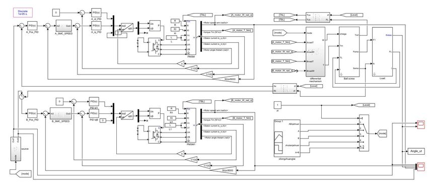
Figure5 shows the active-active mode switching to the active-standby mode(A+B
channel→2A channel) Figure6 shows the active-active mode switching to the
active-standby mode(B channel→A channel)
(a)The angle of air vane
(b) PID control’s speed curve (left) SMC control’s speed curve(right)
Fig. 5. (A+B channel→2A channel).
By observing figure 5, it is clear to know that although the system’s chatting of the PID
control is not very large, but the SMC control’s system curve is much smoother, comparing
the speed curve, the B channel under the PID control can not return to zero due to the static
error, and the SMC control is the better algorithm.
8E3S Web of Conferences 268, 01069 (2021) https://doi.org/10.1051/e3sconf/202126801069
VESEP2020
(a)The angle of air vane
(b) PID control’s speed curve (left) SMC control’s speed curve(right)
Fig. 6. (B channel→A channel).
Looking at Figures 5 and 6, sliding mode control greatly improves the control accuracy
of the system. The sliding mode control has a smaller overshoot and a quicker answer than
the PID control. As shown in Figure 6, when B channel → A channel, the switching time
between speed is about 0.15s, and the speed overshoot is 29.3%. However, when the A+B
channel→2A channel, the switching time between speed is about 0.1s, and the speed
overshoot is 5%.
It can be seen that, compared with the active-standby mode1 switching to the
active-standby mode 2, the overshoot of the active-active mode switching to the
active-standby mode is smaller and the switching time is shorter. The active-active working
mode is better.
5 Summary
This paper builds a model of a dual-motor differential electromechanical servo system that
takes into account inertia, friction load, and clearance. Aiming at the problems of low
stability and poor control accuracy during the process of working mode switching. A new
sliding mode control algorithm is proposed by combining the arctangent function and the
power-law function. Simulation experimental results show that the speed loop sliding mode
control algorithm eliminates speed fluctuations and suppresses controller chatter, increases
robustness, and uses the arctangent function instead of the switching function.
9E3S Web of Conferences 268, 01069 (2021) https://doi.org/10.1051/e3sconf/202126801069
VESEP2020
References
1. D. Arriola and F. Thielecke: Design of fault-tolerant control functions for a primary
flight control system with electromechanical actuators,2015 IEEE AUTOTESTCON,
National Harbor, MD, 2015, pp. 393-402
2. David Arriola, Frank Thielecke: Model-based design and experimental verification of a
monitoring concept for an active-active electromechanical aileron actuation system,
Mechanical Systems, and Signal Processing, vol. 94, pp. 322, 2017.
3. Liu Jinkun, Sun Fuchun. Research on Theory and Algorithm of Sliding Mode Variable
Structure Control And progress[J]. Control Theory and Application, 2007, 24(3):
407-418.
4. YE Chao, LI Hongwen.PMSM Sliding Mode Control Based on Novel Saturation
Function and PI Observer, Journal of Chongqing Institute of Technology,2020, 34(5).
5. Y. Li and L. Liu: The research of the sliding mode control method based on improved
double reaching law,2018 Chinese Control And Decision Conference (CCDC),
Shenyang, 2018, pp. 672-675.
6. Q. Hu, L. Liu, and H. Yang: A sliding mode speed controller based on novel reaching
law of permanent magnet synchronous motor system, 2017 Chinese Automation
Congress (CAC), Jinan, 2017, pp. 954-958.
7. A. K. Junejo, W. Xu, C. Mu, M. M. Ismail, and Y. Liu, "Adaptive Speed Control of
PMSM Drive System Based a New Sliding-Mode Reaching Law," in IEEE
Transactions on Power Electronics, vol. 35, no. 11, pp. 12110-12121, Nov. 2020.
8. Cui Yalong, Yang Yonghao.Research on an Adaptive Fuzzy Sliding Mode Boundary
Layer Control Method for a Hypersonic Vehicle, Computer Measurement &
Control,2014, 22(5):1426-1429,1432
9. Z. Qin, X. He, and D. Zhang, "Nonsingular and fast convergent terminal sliding mode
control of robotic manipulators," Proceedings of the 30th Chinese Control Conference,
Yantai, 2011, pp. 2606-2611.
10. Zengcheng ZHOU, Guoyuan TANG, Hui HUANG, et al.Adaptive nonsingular fast
terminal sliding mode control for underwater manipulator robotics with asymmetric
saturation actuators[J].Control Theory and Technology,2020,18(1):81-91.
11. Aravind M.A., Dinesh N.S., K. Rajanna Application of EMPC for precise position
control of DC-motor system with Backlash[J] Control Engineering Practice, 2020, 100.
12. Jianguo Zhou, Zhiyuan Liu, and Run Pei, "Sliding mode model predictive control with
terminal constraints," Proceedings of the 3rd World Congress on Intelligent Control
and Automation (Cat. No.00EX393), Hefei, 2000, pp. 2791-2795 vol.4.
13. T. Kaletsanos, S. H. Xepapas, and S. N. Manias, "A novel sliding mode fuzzy logic
control technique for induction motor drive systems," 2001 IEEE 32nd Annual Power
Electronics Specialists Conference (IEEE Cat. No.01CH37230), Vancouver, BC, 2001,
pp. 1209-1214 vol.2.
14. D. Chen, H. Du and X. Jin, "Position tracking control for permanent magnet
synchronous motor based on integral high-order terminal sliding mode control," 2017
32nd Youth Academic Annual Conference of Chinese Association of Automation
(YAC), Hefei, 2017, pp. 234-239
15. Brahim BRAHMI, Mark DRISCOLL, Mohamed Hamza LARAKI, et al.Adaptive
high-order sliding mode control based on quasi-time delay estimation for uncertain
robot manipulator[J].Control Theory and Technology,2020,18(3):279-292.
10E3S Web of Conferences 268, 01069 (2021) https://doi.org/10.1051/e3sconf/202126801069
VESEP2020
16. Djemai, M., Busawon, K., Benmansour, K., et al.High-order sliding mode control of a
DC motor drive via a switched controlled multi-cellular converter[J]. International
Journal of Systems Science: The Theory and Practice of Mathematical Modelling,
Simulation, Optimization and Control in Relation to Biological, Economic, Industrial,
and Transportation Systems,2011,42(10/12):1869-18 82.
17. FALLAHA C J, SAAD M, KANAAN H Y, et al. Slidingmode robot control with
exponential reaching law[J]. IEEE Transactions on Industrial Electronics, 2011, 58
( 2): 600 - 610.
18. LUENBERGER D. An introduction to observers[J]. IEEE Transactions on
Automatic Control, 1971, 16 ( 6): 596 - 602.
19. He Yikang. Pulse width modulated(PWM) inverterasynchronous motor system
steady-state space analysis[J]. Transactions of China Electrotechnical Society, 1994,
9(2): 11-15.
20. Olaf Cochoy, Susan Hanke, Udo B Carl. Concepts for position and load control for
hybrid actuation in primary flight controls[J]. Aerospace Science and Technology,
2007, 11(2/3): 194-201.
21. GUO Honggen, WANG Zhiguo. Overview of the Development of Medium and
High Power Space Electric Servo Mechanism [J].Navigation Positioning and Timing,
2016, ( 3): 1 - 5.
22. ZHANG Lisong, HU Youde, XU Lixin. Principle and Design of Servo System
[M].Beijing: Beijing University of Technology Press, 2008.
11You can also read