Theoretical study of heat conduction in the multi-disc brake integrated into the drive wheel AGV during braking
←
→
Page content transcription
If your browser does not render page correctly, please read the page content below
BULLETIN OF THE POLISH ACADEMY OF SCIENCES                                                                                 SPECIAL SECTION
TECHNICAL SCIENCES, Vol. 69(2), 2021, Article number: e136718                                                   Machine modelling and simulations
DOI: 10.24425/bpasts.2021.136718

            Theoretical study of heat conduction in the multi-disc brake
               integrated into the drive wheel AGV during braking
                                   Daniel VARECHA*, Róbert KOHÁR, and Michal LUKÁČ
                    University of Žilina, Faculty of Mechanical Engineering, Department of Design and Mechanical Elements,
                                                    Univerzitná 8215/1, 010 26 Žilina, Slovakia

Abstract. This paper is focused on the theoretical study of heat conduction in the multi-brake system of the automated guided vehicle (AGV).
The study aims to compare the amount of heat generated during braking from 10 m/s until a stop in a brake system based on organic and ceramic
friction material. The theoretical study of heat conduction is solved in Matlab computational software using a derived Fourier partial differential
equation for nonstationary heat conduction. The results of the simulation of the heat conduction are shown in the diagrams and indicate not
only the temperature dependence in the period during braking from a speed of 10 m/s to a stop but also the amount of heat accumulated in the
steel disc during braking. The simulation results show that braking in both brake systems generates approximately the same amount of heat. The
difference occurs in the period of thermal activity, which was influenced by the length of the braking distance. This is caused by a coefficient
of friction that significantly affects the final braking result. Finally, it can be stated that the brake system based on organic material must be
equipped with a steel disc with a minimum thickness of 8 mm. This is because the brake system based on organic friction material has a set
temperature limit of 160 degrees Celsius. The results presented in this study will help an engineer constructor to choose the right procedures
and parameters of geometry for designing the mentioned braking system for the considered AGV.

Key words: simulation; braking systems; one-dimensional heat conduction; multi-disc brake; AGV; ceramic vs. organic brake pads.

1. Introduction                                                            from a battery [2, 3]. The regulation of kinetic energy is ensured
                                                                           by the electric engine brake. However, as the speed increases, so
In this paper, the authors present their theoretical study on heat         does the amount of force of inertia applied to the AGV during
conduction during braking of the integrated multi-disc brake               braking [4, 5]. The current electric engine brake is not designed
concept (Fig. 1).                                                          for braking at high speeds, and the vehicle is not able to stop at
                                                                           a safe distance in crises (sudden braking) [6]. During braking,
                                                                           the drive wheels are locked, and the vehicle tends to slide a few
                                                                           tens of centimetres forward. Currently, with the advent of the
                                                                           4th Industrial Revolution, manufacturing plants are introduc-
                                                                           ing progressive control and organization systems. The fourth
                                                                           industrial revolution is defined as a new level of organization
                                                                           and control over the entire product life cycle value chain [7].
                                                                           The philosophy is increasingly focused on individual customer
                                                                           requirements [7]. The stated AGV is operated by computer con-
                                                                           trol on an electronic data interchange platform [8]. The AGV
                                                                           operation is planned in the so-called virtual logistics corridors
Fig. 1. Concept of drive wheel with integrated multi-disc brake [4, 6]     between the production line and warehouse, and they can be
                                                                           tens of meters apart [9]. The considered transport speed of the
                                                                           AGV in the said corridor is set up to 10 m/s (»28 km/h). Trans-
   The brake system is integrated into the free space drive                port must be carried out with powerful towing AGVs. The brak-
wheel of the automated guided vehicle (AGV). This type of                  ing must be smooth in the form of minimizing sharp braking
multi-disc brake is currently the subject of research at the               and accelerating because driving and braking style has a direct
Department of Design and Mechanical Elements of the Uni-                   impact on the range of the AGV [10, 11]. The vehicle does
versity of Zilina in Zilina. The present market offers AGVs                not pollute the air in the production and warehouse areas [11].
whose working speeds are at the level of 2 m/s [1]. The AGV is
powered by an electric motor, which is supplied with electricity
                                                                           2. Multi-disc brake
*e-mail: daniel.varecha@fstroj.uniza.sk                                    In the late 1980s, automatic planetary gearboxes were equipped
Manuscript submitted 2020-08-21, revised 2020-11-04, initially accepted    with friction discs with organic friction pads [12]. The friction
for publication 2020-12-02, published in April 2021                        discs formed part of the clutches and brakes in the listed gearbox

Bull. Pol. Acad. Sci. Tech. Sci. 69(2) 2021, e136718                                                                                             1

       © 2021 The Author(s). This is an open access article under the CC BY license (http://creativecommons.org/licenses/by/4.0/).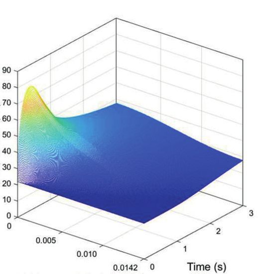
D. Varecha, R. Kohár, and M. Lukáč

[12‒14]. The organic brake pad of the discs has some properties              2.1. The concept of a multi-disc brake. The construction of
that predispose it to the construction of brake systems [14].                the multi-disc brake consists of two types of discs (spacers
In the first place, the organic material has an almost constant              & washers). The first type of disc is made of a friction material
course of the coefficient of friction depending on the slip speed            (Fig. 3a) and the second of steel for brake systems (Fig. 3b).
of the friction discs compared to the ceramic or metallic fric-
tion material for common industrial use. In the case of ceramic
friction material, the value of the coefficient of friction reaches                                 (a)                                 (b)
a maximum after the start of the abrasion process (braking) and

                      120℃                              20℃
       0.40

       0.30

       0.20                                                                                         Fig. 3. Friction and steel disc [12]

       0.15
 f                                                                               The inner space of the drive wheel is limited in size. The
       0.10                                                                  size of the friction surface is selected, which is the most dimen-
                                                                             sionally suitable for the inner space of the wheel (Table 1).
                                                                             Four types of steel discs are proposed ranging from 1.75 mm
       0.05                                                                  to 14.2 mm in thickness. The aim is to investigate the effect of
                                                                             the thickness of the steel disc on the amount of heat absorbed.

          0                                                                                               Table 1
              0       20       40      60       80      100      120 rad/s
                                                                                         Dimensional parameters of the multi-disc brake
                                      Δω
                                                                                   Symbol                   Value        Units          Description
     Fig. 2. Coefficient of friction of different friction materials [12]
                                                                                       D1                    148          mm          Outside diameter
                                                                                       d2                    106          mm           Inside diameter
then decreases and stabilizes [15] (Fig. 2). This statement is
made in several publications [16].                                                h friction disc            2.6          mm         Thickness (friction)
    With organic friction material in the region of low slide
                                                                                   h steel disc           1.75 ÷ 14.2     mm          Thickness (steel)
speeds, the coeff icient of friction even decreases with the
decreasing slide speed. The static coeff icient of friction is
lower than the dynamic. These organic brake pad properties                       The right functionality of a multi-disc brake based on
have led to better gear shifting in planetary gearboxes. The                 organic friction material depends on the operating tempera-
organic friction brake pads serve as good damping of torsional               ture of the oil. During frequent braking, the temperature in
vibrations, which arose at the beginning of the gearshift, or                the brake system must not exceed 160°C. It is desirable that the
during a sudden increase in the pressure in the brake system                 thickness of the steel disc is cooled fast enough. For ceramic
and thus the friction torque. This statement only applies if                 friction material, the maximum braking temperature may
the organic friction brake pad is in continuous contact with                 exceed 160°C because the brake system is dry (no oil used).
the disc during braking. In terms of operating conditions, the               The parameters of the materials used in the multi-disc brakes
angular velocities of the planetary gearbox are higher than the              are given in Table 2.
considered speed of the AGV during operation. Ultimately, it
follows from the above text that it is appropriate to consider                                               Table 2
the use of a multi-disc brake based on organic friction mate-                                Thermal parameters of the multi-disc brake
rial. The disadvantage of brake pads based on organic friction                    Description                Symbol     Ceramic         Steel      Organic
material is their very poor thermal conductivity, which forms
a thermally insulating layer from the layer of organic (paper)                 Specific heat [J/kg]            [c]         420           477         1210
brake pad. The brake system based on organic material uses                    Mass destiny     [kg/m3]         [ ρ]       5500          7850          700
oil for its function to increase adhesion during braking. How-
                                                                              Thermal conductivity
ever, with an increasing temperature, the oil loses its proper-                coefficient [W/m]
                                                                                                               [λ ]        42            42          0.092
ties (degrades), and the brake system loses its functionality.
                                                                               Thermal diffusivity
Ultimately, the oil quality affects the efficiency of the brake                                                [a]      1.82£10 ‒5    1.12£10 ‒5   10.8£10 ‒8
                                                                                    [m 2/s]
system.

2                                                                                                         Bull. Pol. Acad. Sci. Tech. Sci. 69(2) 2021, e136718
Theoretical study of heat conduction in the multi-disc brake integrated into the drive wheel AGV during braking

3. Simulation braking AGV                                                                v(t) = ∫ a dt = –
                                                                                                                FB
                                                                                                                      £ t + c1 ,(2)
                                                                                                                m
The basic weight of the AGV is 520 kg (Table 3). The design
of the AGV allows transporting 3020 kg of cargo (including                                                 FB
weight AGV) at a speed of up to 10 m/s. The braking simu-                       x(t) = ∫ v(t) dt = –             £ t 2 + v0 £ t + c2 .(3)
                                                                                                         2¢ m
lation was performed for two friction materials, considering
all the resistance that acts on the AGV during the operation               The results of the braking simulation are shown in Table 4
(rolling resistance, air resistance, etc.). The first friction mate-       below.
rial is based on an organic basis with a coefficient of friction
f = 0.12 and the second type of ceramic friction material with                                           Table 4
a coefficient of friction f = 0.31.                                                    Parameters for braking with friction material
                                                                                                  f = 0.12 and f = 0.31
                                  Table 3
                                                                                       Coefficient of friction:           Coefficient of friction:
                       Parameters of considered AGV                          Load
                                                                                              f = 0.12                           f = 0.31
 Symbol         Value       Unit      Description             Note
                                                                                       Braking     Braking route          Braking    Braking route
                                                                              [kg]
     v            10         m/s          Speed          Max speed                     time [s]        [m]                time [s]       [m]

    M            520         kg           Weight        AGV weight           2020       1.062          5.33                0.59           3.18

   M Full        3020        kg           Weight       Shipping weight       3020        1.24          6.20                0.76           4.07

    Using the simulation of braking, the braking distance                  4. Theoretical study
is detected and total time to stop for both types of friction
materials at the considered two driving modes and a speed of               In the braking system based on a ceramic friction material, the
10 m/s. In the first operating mode, the AGV transports a load             kinetic energy is transformed into thermal energy by using dry
of 2020 kg and in the second a load of 3020 kg, including its              friction effects and, after that, dissipated into and absorbed to
own weight. The brake system is located on one drive axle. The             a greater extent by the steel discs, and a small percentage is
resulting data of the braking distance and total time to stop are          passed into the surrounding space and floor [17]. The brake
needed to simulate the heat conduction on the surface of the               system based on organic friction material is based on a wet
steel disc during braking. The simulation of AGV braking was               brake (in oil). In this case, the heated oil is used in braking,
made in the Matlab calculation software using Newton equa-                 which has the manufacturer’s prescribed recommended oper-
tions of motion for deceleration (1), speed (2), and distance              ating temperature.
(3). All driving resistances, such as resistance of rolling, the
resistance of air, and resistance of inertia, were considered in           4.1. Conversion of kinetic energy into thermal energy.
the calculations. Figure 4 shows the acting forces on the AGV              During braking from the operating speed (v = 10 m/s) to a stop
in consideration.                                                          (v = 0 m/s), the kinetic energy (EK ) with the rotational energy
                                                                           (ER ) of four wheels acts on the AGV. The sum of these energies
                                     FB                                    forms the total braking energy (EB), which is needed for the
                             a=–          ,(1)                            safety stop of the AGV (4).
                                     m
                                                                                          ³              ´            ³              ´
                                                                                              1                1
                                                                                  EB =          £ M £ v 2 + 4£ £ I £ ω 2                 ,(4)
                                                                                              2                2
                                             N
                                                                 y         where: E K is£the
                                                                                                                £ ¤
                                                                                             kinetic energy J ; ER is the rotational£ energy
            v                                                                             ¤
                                                                           of the wheel J ; I is the moment of inertia of the wheel  kg.m 2
                                                                                                                                            ¤
                                                                                                                                             ;
                                                                                                      £    ¤                            £ ¤
                                                                           w is the angular velocity Rad/s ; M is the weight of AGV kg .
                                                                               The angular velocity (w) from Eq. (4) is a replaced rela-
                                                                           tionship of (5).
                                                         FB
                                                                                                                           v
                                                                                              v = R £ω → ω =                 .(5)
                                                                                                                           R
      x
                                             FG
                                                                              The moment of inertia of the wheels (6) is also added to
                Fig. 4. Forces acting on the AGV [authors]                 Eq. (4).

Bull. Pol. Acad. Sci. Tech. Sci. 69(2) 2021, e136718                                                                                                 3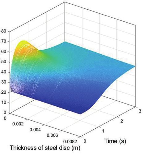
D. Varecha, R. Kohár, and M. Lukáč
1 4.2. Heat conduction simulation results. The classical theory
I= £ m £ R 2,(6)
2 of heat conduction is based on the Fourier law [18]. The basic
heat equation is solved using the Fourier transform. Four thick-
where: R is the diameter of the drive wheel [m]; m is the weight nesses from 1.75, 4.2, 8.2 to 14.2 mm steel disc are selected for
of the wheel [kg]. the simulation of heat conduction. The braking time calculated
The equation for total braking energy (4) is rewritten in the from the previous simulation is important and will be used in
following mathematical Eq. (7) and subsequently adjusted (7.1). the next simulation of heat conduction. A reference temperature
corresponding to the evenly heated steel disc is calculated (9).
³ ´ ³ ´2
M£v2 1 v
EB = + 4£ £ m £ R 2 £ ,(7) EB– q
2 2 R ϑ0 = = ,(9)
c £ ϱ £ Sp £ h c£ ϱ£ h
v2
EB = £( M + (2£ m)) .(7.1) £ ¤
2 where: c is the specific
£ heat¤ capacity J/kg ; ϱ is the mass des-
tiny
£
of
¤
the steel disc kg/m3 ; h is the thickness of the steel disc
The heat conduction (8) that acts on the surface of one brake mm .
disc is defined as the proportion of the total brake energy with From several works about non-stationary, one- dimensional
the effective friction surface of the disc and their number. heat conduction, a dimensionless Fourier number is known,
which contains the characteristic values of the described pro-
EB cess (10) [19, 20]
q= .(8)
j£Sp
a £ tb
F0 = ,(10)
The heat conduction (Fig. 5) is assumed perpendicular to h2
the friction surface
£ ¤ in the direction of the disc, where: q is heat £ ¤
2
conduction
£ ¤ J/m ; SP is the effective area of one £ ¤
side of the where:
£ ¤
a is the thermal diffusivity m 2/s ; t b is the braking
disc mm2 ; j is the number of friction surfaces – . time s .
To show the results in a dimensionless representation, it is
more advantageous to introduce the reciprocity of the Fourier
number (11)
Friction surface 1 h2
Heat transfer G= = .(11)
F0 a £ tb
or insulated
boundary
Heat conduction is also possible to describe the use of
non-integer order models [20, 21]. By introducing the refer-
Heat flow q ence temperature (9) into Eq. (12), the dimensionless numbers
α=0 in the diagram are changed to the course of temperature during
braking. The end of the curve in the diagram represents the
temperature that the steel disc accumulated during the braking
from speed 10 until coming to a complete stop. Using Eq. (12)
below, the time course of the heat conduction on the surface of
the considered discs is calculated. While t = t* for t ∙ tb , and
Fig. 5. Spatial boundary conditions for organic material [12] t* = tb if t > tb ,
à ! à ! m2 £ π 2
µ
t t2
ϑp 2 £ t* t* 4 1 G t* –
£G £ ∑
£ ¡
= £ 1¡ + £ 1+ ¡ £e G tb tb ¡
ϑ0 tb 2 £ tb π2 m =1 m2 m2 £ π tb
à ! (12)
m2 £ π 2
G – t
¡ 1+ £e G £ ,
m2 £ π tb
where: ϑp is the initial temperature [°C]; ϑo is the temperature of an evenly heated disc [°C]; t* is the observed time [s]; t is the
computing time [s].
4 Bull. Pol. Acad. Sci. Tech. Sci. 69(2) 2021, e136718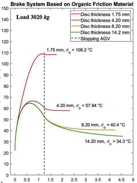
Theoretical study of heat conduction in the multi-disc brake integrated into the drive wheel AGV during braking

    As can be seen from the diagrams (Figs. 5a–5b), the thinner                      compared to the previous brake system based on organic fric-
disc thicknesses absorb a large amount of heat. It appears that                      tion material (Figs. 6a–6b).
when designing the said brake system, the disc thicknesses from                          The intensity of the heat conduction seems to be the same for
8.2 mm will suffice. When considering a brake system based                           both brake systems, and the difference occurs during the conduc-
on a ceramic friction material, the braking distances are shorter                    tion. However, the difference between the absorbed heat between

    a)                                                                               b)

                                                                                          Temperature (°C)
         Temperature (°C)

                                                Time (s)                                                              Time (s)

                                       Fig. 6. Temperature course on the disc surface during braking (organic friction material)
         Temperature (°C)

                                                                                          Temperature (°C)

                                                Time (s)                                                              Time (s)

                                       Fig. 7. Temperature course on the disc surface during braking (ceramic friction material)

Bull. Pol. Acad. Sci. Tech. Sci. 69(2) 2021, e136718                                                                                                5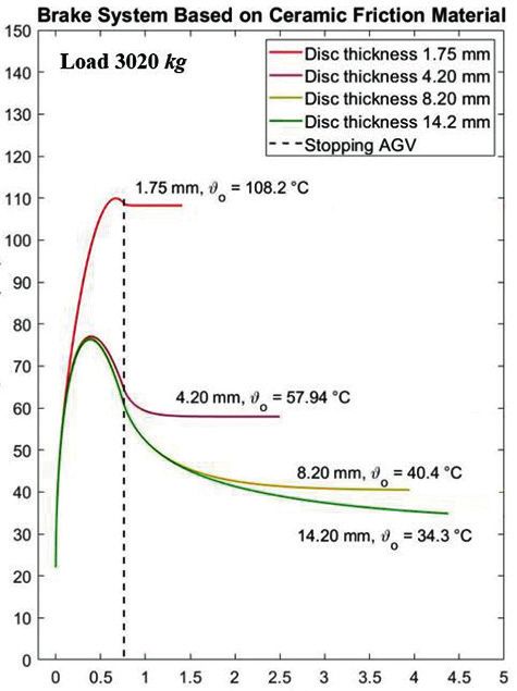
D. Varecha, R. Kohár, and M. Lukáč
the thicknesses of the discs 8.2 to 14.2 mm is almost negligible. differential Eq. (13). Equation (13) is coming on the equation
It is necessary to verify this fact and further investigate the dif- for calculating the disc surface temperature (12). The symbol
ference in the absorbed heat between the said steel discs. “x” expresses the distance of the specific cross-section area
The heat conduction simulation is performed only for the from the surface steel disc, where the value of the accumulated
brake system based on an organic material because the tempera- heat is investigated. The symbol “h” expresses the thickness of
ture limit of its operation activity is limited up to 160°C. This the monitored steel disc (Fig. 8). Here, the same numerical con-
verification will help the designer to choose the correct steel ditions apply as for the mathematical relationship from Eq. (12).
disc thickness for the brake system. In this way, it is possible to find out at what distance from the
surface the steel disc heats up during braking.
5. Heat conduction in a specific cross-section ϑ(x, t) 2 £ t*
Ã
t*
!
4
= £ 1¡ + £G £
In the following lines, it is verified how large the difference in ϑ0 tb 2 £ tb π2
the absorbed heat is between the thicknesses of 8.2 and 14.2 mm µ 
cos m £ π £ x
à !
from the surface to the specific cross-section area of the disc. h G t*
The calculation of the temperature into the specific cross-sec- £ ∑
m =1 m2
£ 1+
m2 £ π
¡
tb
£ (13)
tion area of the disc is solved according to the Fourier partial
m2 £ π 2
µ
t t*
¶ Ã ! m2 £ π 2 t
– G
x £e G
£ ¡
tb tb ¡ 1+ £e G
£
tb ,
m2 £ π
where: t = t* for t ∙ tb , t* = tb if t > tb .
The heat conduction in the brake system is only monitored
when braking from a speed of 10 m/s to a full stop. Since the
AGV operates in two operating modes, for each type of braking
h R system, two diagrams of the heat conduction on the surface of
1 the steel disc and also at a specific distance from the surface
R2 steel disc are given.
5.1. Heat conduction for a disc 8.2 mm thick. The diagrams
Fig. 8. Schematic view of steel disc [authors] in Fig. 9 and Fig. 10 show the time course of the temperature in
a) b)
Temperature (°C)
Temperature (°C)
Time (s)
Fig. 9. Organic friction material and steel disc in the thickness of 8.2 mm, load 2020 kg
6 Bull. Pol. Acad. Sci. Tech. Sci. 69(2) 2021, e136718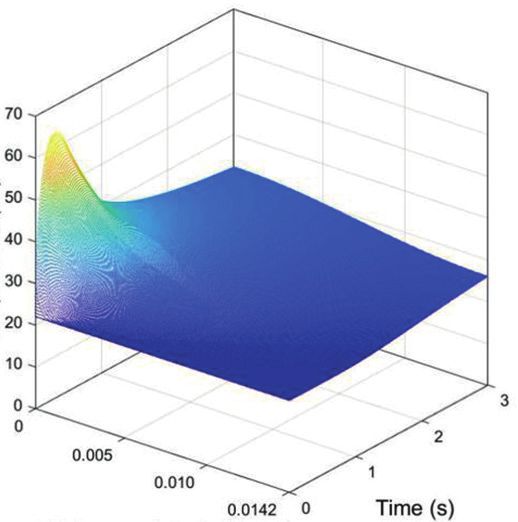
Theoretical study of heat conduction in the multi-disc brake integrated into the drive wheel AGV during braking
a) b)
Temperature (°C)
Temperature (°C)
Time (s)
Fig. 10. Organic friction material & steel disc in the thickness of 8.2 mm, load 3020 kg
the brake system based on the organic material with a steel disc 8 mm, a heat conduction simulation was created for a 14.2 mm
thickness of 8.2 mm for the first and second operating modes. thick steel disc (Figs. 11 and 12). When the brake system is
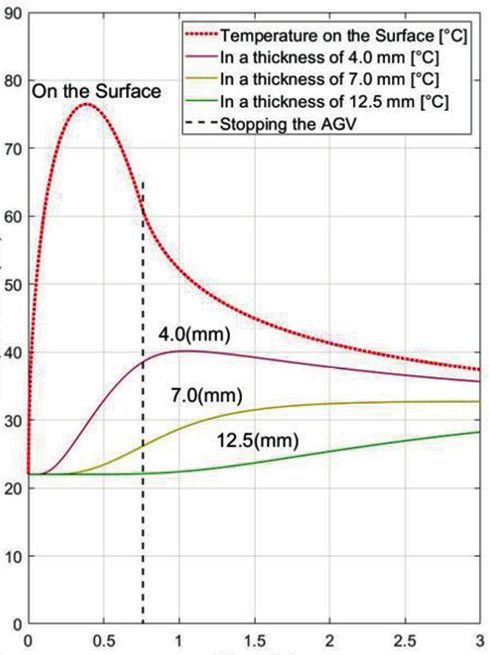
The three-dimensional diagram (Fig. 9a) shows the time equipped with a 14.2 mm thick steel disc, it absorbs a very
course of the temperature during braking on the surface and small amount of heat and also cools down very quickly. It can
in the complete body of the steel disc. The second diagram be seen in Figs. 11 and 12 that in the first operating mode, the
(Fig. 9b) shows the time course of the temperature on the sur- steel disc heats up only to two-thirds of its thickness from the
face of the steel disc and in a specific cross-section area from the surface of the disc. In the second operating mode, the time
surface. As in the previous case, Figs. 10a-10b show diagrams course of the temperature results was very similar. It seems
that depict the time course of the temperature in a brake system this setting would be the most suitable for a brake system that
based on organic friction material with a steel disc 8.2 mm thick is based on organic friction material. During repeated braking,
but using the second operating mode. As can be seen from the the brake system would not absorb a large amount of heat and
diagrams (Figs. 9 and 10), in both operating modes, the steel would be sufficient to maintain a permissible operating tem-
discs received a small amount of heat. In the case of 3020 kg perature level up to 160°C. This statement applies only under
weight, the temperature was from 10 to 15°C more than in the the given operating conditions and the use of the considered
first operating mode (2020 kg). When evaluating the results of dimensions of the braking system.
the heat conduction, it must be borne in mind that the brake
system based on an organic material uses oil to its function.
Therefore, by repeated braking, the temperature of the oil can- 6. Conclusion and discussion
not exceed 160°C. Otherwise, the oil degrades, and the brake
system would lose its effectiveness very quickly. It is also very The subject of the theoretical study was to compare the influ-
important to note in the diagrams how much heat the investi- ence of friction materials on the resulting braking tempera-
gated thicknesses of the steel discs absorb and, last but not least, ture, which rises during AGV braking. As can be seen from
how fast the temperature drops after braking. It appears that in the diagrams, when the weight increases, the braking distance
the case of the first operating mode, the repeated braking of the and the temperature in the braking system begin to increase as
braking system would probably not absorb a large amount of expected. The results of the simulation of the heat conduction
heat and the braking system would cool down quickly enough. also indicate that the resulting temperature on the surface of the
steel disc did not differ significantly in both operating modes
5.2. Heat conduction for a disc 14.2 mm thick. Like the sim- (65 » 78°C). The only difference that occurs is the period of
ulation of the heat conduction for a disc with a thickness of the heat conduction, which depends on the braking distance of
Bull. Pol. Acad. Sci. Tech. Sci. 69(2) 2021, e136718 7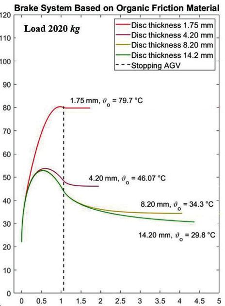
D. Varecha, R. Kohár, and M. Lukáč

      a)                                                                         b)

                                                                                      Temperature (°C)
Temperature (°C)

                                                              Time (s)

                   Thickness of steel disc (m)

                                                                                                                       Time (s)
                                   Fig. 11. Organic friction material and steel disc in the thickness of 14.2 mm, load 2020 kg

     a)                                                                          b)
                                                                                      Temperature (°C)
Temperature (°C)

                                                              Time (s)

                   Thickness of steel disc (m)

                                                                                                                       Time (s)
                                   Fig. 12. Organic friction material and steel disc in the thickness of 14.2 mm, load 3020 kg

      8                                                                                                  Bull. Pol. Acad. Sci. Tech. Sci. 69(2) 2021, e136718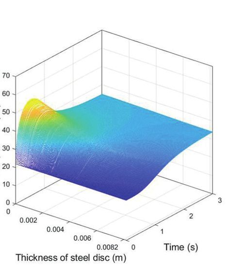
Theoretical study of heat conduction in the multi-disc brake integrated into the drive wheel AGV during braking

the AGV. Larger thicknesses of steel discs do not absorb large           epicyclic gear train (planetary gear) and incorporated it into the
amounts of heat during braking from a speed of 10 m/s to a full          current requirements in the field of logistic vehicles (AGV).
stop. It is assumed that they will not become very heated up.            In a theoretical study, controlling the brake system using an
The results of the simulation of the heat conduction show that           electric servo motor, not hydraulic energy, is considered. In the
it is necessary to equip the brake system with discs of at least         future, it is planned to create an experiment of braking which
a minimum thickness of 8 mm and more. Increase in the num-               considers the braking system and verify the data found by the
ber of discs. However, adding more friction and steel discs into         simulation.
the brake system causes an increase in the braking torque and,               Last but not least, the quality of the simulation in this theo-
ultimately, a shortening of the braking distance.                        retical study is several times higher at a numerical and graphic
     The brake system based on a ceramic friction material is            level than in the habilitation thesis from the 1980s. This is
not limited by the maximum operating temperature of 160°C                due to the advances in the fields of computer simulation and
as with the braking system based on an organic material with             modelling. At present, it can be stated that using the computer
regard to the same considered operating terms of the AGV.                simulation method we can solve much more complex mathe-
The design of the said brake is dry and a cleaner operation is           matical issues than in the past.
expected compared to a brake system based on organic friction
material (in oil). The only question is the resulting comfort            Acknowledgements. The research was supported by the Slo-
during braking which is verifiable only by experiment. The               vak Research and Development Agency under contract No.
disadvantage is that the field studies, which are perceived as           APVV-18‒0450, and by the project of the Research & Devel-
the most credible, provide information about the brake system            opment Operational Programme funded by the ERDF: “Com-
until after the brake has been manufactured [22]. The advan-             petency Centre for Knowledge technologies applied in Inno-
tage of organic materials is the almost constant coefficient of          vation of Production system in Industry and Services”, ITMS:
friction, which will ultimately have a positive effect on the            26220220155.
comfort of braking. AGV braking should be smooth, with no
torsional vibrations. For this reason, organic friction material
was selected for comparison. Furthermore, the publication [22]           References
states that when using an automatic brake system, there are
no sudden changes in the friction properties of the brake pads            [1] D. Varecha, R. Kohar, and F. Brumercik, “AGV brake system
when the friction material is heated. However, this only applies              simulation”, LOGI – Scientific Journal on Transport and Logis-
                                                                              tics 10(1), p. 9 (2019).
to the ceramic dry brake. It would certainly be appropriate for
                                                                          [2] G. Kovács, “Novel supply chain concepts and optimization of
future research to focus on how to dissipate heat more quickly                virtual enterprises to reduce cost, increase productivity and boost
from the wheel body. For example, by incorporating a fin heat                 competitiveness”, Bull. Pol. Acad. Sci. Tech. Sci. 66(6), 973–980
exchanger to dissipate the heat between the wheel body and                    (2018).
the air. Several highly qualified publications address this issue,        [3] P. Piotrowski, D. Baczyński, S. Robak, M. Kopyt, M. Piekarz,
for example [23]. Many of the mathematical equations used in                  and M. Polewaczyk, “Comprehensive forecast of electromobil-
this theoretical study were taken from the habilitation work of               ity mid-term development in Poland and its impacts on power
our colleague. The habilitation thesis was published in a book                system demand”, Bull. Pol. Acad. Sci. Tech. Sci. 68(4), 697–709
form in the 1980s and there is no online access to it. All literary           (2020).
sources used by our colleague come from foreign (German,                  [4] M. Belorit et al., “Description of the bearing check program for
Austrian) and also domestic professional literature. Neverthe-                countershaft gearboxs”, Proceding of 58th International Confer-
                                                                              ence of Machine Design Departmens (ICDM), Prague, 2017, pp.
less, these mathematical formulas (theory) are traceable and
                                                                              32–35.
used to this day. They are mentioned in the literature in [24],           [5] M. Jacyna, R. Jachimowsky, E. Szczepański, and M. Izdebski,
for instance.                                                                 “Road vehicle sequencing problem in a railroad intermodal ter-
     The habilitation thesis is focused on the research of a brake            minal – simulation research”, Bull. Pol. Acad. Sci. Tech. Sci.
system of an epicyclic gear train (also known as a planetary                  68(5), 1135–1148 (2020).
gear) for commercial vehicles and trucks. The research was                [6] D. Varecha, R. Kohar, and T. Gajdosik, “Optimizing the braking
focused not only on the design but also on the heat conduction                system for handling equipment”, IOP Conf. Ser.: Mater. Sci.
in the brake system during shifting gears.                                    Angl. 659, 012062 (2019).
     The effect of the size and number of friction discs on the           [7] S. Devansh, P. Sahil, and R.S. Aravind, “Industry 4:0: Tools and
resulting temperature during gear shifting was also investigated              Implementation”, Manag. Prod. Angl. Rev. 10(3), 3–13 (2019).
in the thesis. It is worth mentioning the results achieved during         [8] K. Chwesiuk, “Integrated computer system of management in
                                                                              logistics”, Arch. Transp. 23(2), 153–163 (2011).
the development, which were used at that time in the design
                                                                          [9] T. Kornuta, C.C. Zieliński, and T. Winiarski, “A universal archi-
of planetary gearboxes. Although the technology of planetary                  tectural pattern and specification method for robot control sys-
gearboxes has advanced to a higher level, the theory described                tem design”, Bull. Pol. Acad. Sci. Tech. Sci. 68(1), 3–29 (2020).
in the habilitation thesis from the 1980s is still relevant. That        [10] L. Kucera, T. Gajdosik, I. Gajdac, M. Mruzek, and M. Toma-
is why my colleagues and I decided to create a multi-disc brake               sikova, “Simulation of real driving cycles of electric cars in
for the AGV, based on our elder colleague’s research. We have                 laboratory conditions”, Communications – Scientific Letters of
taken over the technology of the multi-disc brake system of the               the University of Zilina, 19(2A), 42–47 (2017).

Bull. Pol. Acad. Sci. Tech. Sci. 69(2) 2021, e136718                                                                                           9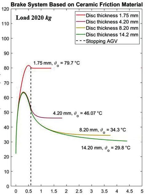
D. Varecha, R. Kohár, and M. Lukáč

[11] M. Mruzek, I. Gajdac, L. Kucera, and T. Gajdosik, “The possi-        [18] U. Siedlecka,”Heat conduction in the finite medium using the
     bilityies of increasing the electric vehicle range”, TRANSCOM             fractional single-phase-lag model”, Bull. Pol. Acad. Sci. Tech.
     – International Scientific Conference on Sustainable, Modern              Sci. 67(2), 401–407 (2019).
     and Safe Transprt, Procedia Engineering, 192, 621–625, (2017).       [19] M. Lenarczyk and R. Domański, “Investigation of non-fourier
[12] V. Kraus, Výpočet teplôt radiacích lamelových spojok a bŕzd               thermal waves interaction in a solid material”, Arch. Thermodyn.
     (Calculation of temperature multi-disc shifting brake and shift-          40(1), 115–126 (2019).
     ing clutches), Habilitation thesis, p. 70, Žilina (1980), [in Slo-   [20] D. Spałek, “Two relations for generalized discrete fourier trans-
     vak].                                                                     form coefficients”, Bull. Pol. Acad. Sci. Tech. Sci. 66(3), 275–281
[13] M. Lukac, F. Brumercik, L. Krzywonos, and Z. Krzysiak, “Trans-            (2018).
     mission system power flow model”, Communications – Scien-            [21] K. Oprzędkiewicz, W. Mitkvski, E. Gawin, and K. Dziedzic,
     tific Letters of the University of Zilina, 19(2), 27‒31, (2017).          “The caputo vs. caputo-fabrizio operators in modeling of heat
[14] A. Estevez-Torres et. al., “Fourier analysis to measure diffusion         transfer process”, Bull. Pol. Acad. Sci. Tech. Sci. 66(4), 501–507
     coefficients and resolve mixtures on a continuous electrophore-           (2018).
     sis chip”, Anal. Chem. 79(21), 8222–8231, (2007).                    [22] Y. Slavchev, L. Dimitrov, and Y. Dimitrov, “3-D computer re-
[15] A.W. Orlowic, M. Mróz, G. Wnuk, O Markowska, W, Homik,                    search and comparative analysis of dynamic aspect of drum
     and B. Kolbusz, “Coefficient of friction of a brake disc-brake            brakes and caliper disc brakes”, Arch. Mech. Eng. 65(2), 253–276
     pad friction couple”, Arch. Foundry Eng. 16, 196–200 (2016).              (2018).
[16] F. Talati and S. Jalalifar, “Analysis of heat conduction in disc     [23] T. Muszyńsky and S. Kozieł, “Parametric study of fluid flow and
     brake system”, Heat Mass Transfer 45, 1047 (2009).                        heat transfer over louvered fins of air heat pump evaporator”,
[17] D.P. Milenković et al., “The influence of brake pads thermal              Arch. Thermodyn. 37(3), 45–62 (2016).
     conductivity on passenger car brake system efficiency”, Therm.       [24] K. Wolf, Integral transforms in science and engineering, pp.
     Sci. 14, 221–230 (2010).                                                  255–378, 1st Edition, Springer US, Boston, 1979.

10                                                                                              Bull. Pol. Acad. Sci. Tech. Sci. 69(2) 2021, e136718
You can also read