Transport System Telematics
←
→
Page content transcription
If your browser does not render page correctly, please read the page content below
International Scientific Journal published quarterly as the organ of the Polish Association of Transport Telematics

   Archives of
            Transport System
              Telematics

                                            Volume 4

                                               Issue 2

                                           May 2011

Editor-in-Chief Prof. Jerzy Mikulski                                                                 http://pstt.eu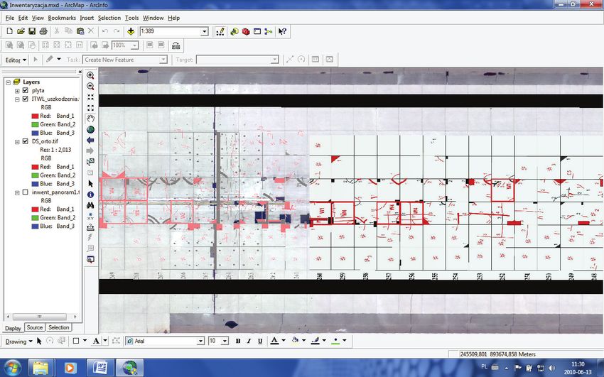
Archives of                                                                                          Volume 4

                              Transport System                                                                                    Issue 2

                                Telematics                                                                                   May 2011

                   Editorial Board of the Journal           W. Suchorzewski         Warszawa, Poland
    Editor – in – chief Jerzy Mikulski                               M. Svítek      Prague, Czech Republic
     Associate Editor    Dorota Bartoszek                            A. Szeląg      Warszawa, Poland
     Assistant Editor    Szymon Surma                               J. Szpytko      Kraków, Poland
     Technical Editor    Renata Skowrońska                          E. Szychta      Radom, Poland
                                                                     G. Tarnai      Budapest, Hungary
                                                                         Z. Toš     Zagreb, Croatia
                International Programming Council
                                                              W. Wawrzyński         Warszawa, Poland
        Chairman
                                                                  R. Wawruch        Gdynia, Poland
           A. Janota      Żilina, Republic of Slovakia
                                                                   A. Weintrit      Gdynia, Poland
      Vice chairman
                                                                B. Wiśniewski       Szczecin, Poland
           A. Bialoń     Katowice, Poland
                                                                     K. Wydro       Warszawa, Poland
        Members:
          M. Bregulla    Ingolstadt, Germany
         K. Chwesiuk     Szczecin, Poland
            J. Dyduch    Warszawa, Poland
        W. Filipowicz    Gdynia, Poland
        M. Franeková     Żilina, Republic of Slovakia
            A. Fellner   Katowice, Poland
            S. Gucma     Szczecin, Poland
       J. Januszewski    Gdynia, Poland
          A. Kalašová    Żilina, Republic of Slovakia
           D. Kevicky    Żilina, Republic of Slovakia
                B. Kos   Katowice, Poland                A Quarterly of PSTT
           O. Krettek    Aachen, Germany
            R. Krystek   Gdańsk, Poland                  Published by:
                                                         Polish Association of Transport Telematics
          A. Lewiński    Radom, Poland
              M. Luft    Radom, Poland
            Z. Łukasik   Radom, Poland
           J. Michalík   Żilina, Republic of Slovakia
          J. Młyńczak    Katowice, Poland
          W. Nagórny     Katowice, Poland                Editorial Office Address
                                                         Polish Association of Transport Telematics
          G. Nowacki     Warszawa, Poland
                                                         5/3 Józefa Gallusa Str.
           S. Oszczak    Olsztyn, Poland
                                                         40594 Katowice, POLAND
     Z. Pietrzykowski    Szczecin, Poland
        B. Pochopień     Gliwice, Poland                 Editorials e-mail:
          K. Rástočný    Żilina, Republic of Slovakia    secretariat@pstt.eu
             J. Spalek   Żilina, Republic of Slovakia
                                                         Printed in Poland
                R. Srp   Prague, Czech Republic
            Z. Stocko    Lviv, Ukraine
                                                         All papers have been accepted for publication after reviewing process.

2                                                                        © Copyright by PSTT , All rights reserved. 2011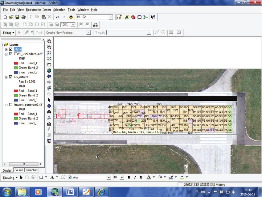
Contents
The use of GIS for the technical examination of take-off airport road  . . . . . . . . . . . . . . 4
     B. GRZĘDZIŃSKI
Different measures for load securing create barriers in international
road freight transport  . . . . . . . . . . . . . . . . . . . . . . . . . . . . . . . . . . . . . . . . . . . . . . . . . . . . . . . . .  10
     J. JAGELCAK, J. GNAP
Structure of interlocking table . . . . . . . . . . . . . . . . . . . . . . . . . . . . . . . . . . . . . . . . . . . . . . . . . .  18
     M. JURCZAK
Intelligent Transport Systems and Safety in Road Traffic  . . . . . . . . . . . . . . . . . . . . . . . . .  25
     A. KALAŠOVÁ, Z. KRCHOVÁ
Impact of human factor on likelihood of aircraft accident . . . . . . . . . . . . . . . . . . . . . . . .  29
     J. KOZUBA
Safety mechanisms of Open Safety profile and their modelling . . . . . . . . . . . . . . . . . .  37
     J. ĽUPTÁK, M. FRANEKOVÁ
Safety mechanisms of ZigBee technology for safety-related
industrial applications . . . . . . . . . . . . . . . . . . . . . . . . . . . . . . . . . . . . . . . . . . . . . . . . . . . . . . . . . .  43
     T. ONDRAŠINA, M. FRANEKOVÁ
Czech ITS 2020 Vision  . . . . . . . . . . . . . . . . . . . . . . . . . . . . . . . . . . . . . . . . . . . . . . . . . . . . . . . . . .  48
     R. SRP
Option of technique of railway crossings securing implementation
to a safe crossing of tram tracks and a road  . . . . . . . . . . . . . . . . . . . . . . . . . . . . . . . . . . . . .  52
     Z. TOŠ, Z. VIDUKA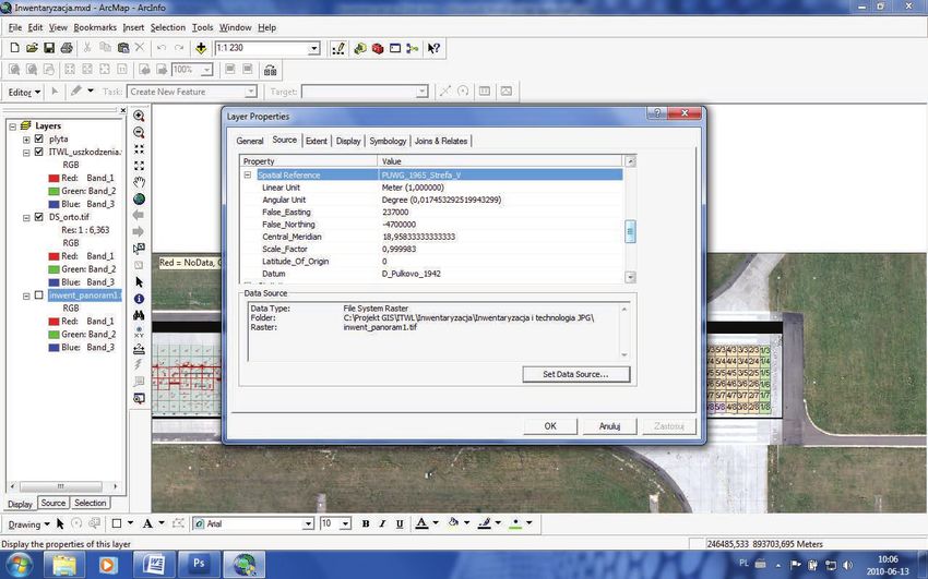
Archives of                                                                                         Volume 4

                               Transport System                                                                                     Issue 2

                                 Telematics                                                                                  May 2011

      The use of GIS for the technical
    examination of take-off airport road
              B. GRZĘDZIŃSKI
              Górnośląskie Towarzystwo Lotnicze S.A. (Upper Silesian Aviation Group)
              EMAIL: bgrzedzinski@gtl.com.pl

              ABSTRACT
              The study covers the design of a GIS project presenting the usefulness of GIS tools for monitoring the
              runway condition using Katowice International Airport in Pyrzowice as an example.
              The study was used in evaluating the possibility of introducing a system of cooperation between the
              following enities engaged in maintaining airport pavement in Katowice International Airport in Py-
              rzowice within one system

              KEYWORDS: GIS, airport road

                                                                        The aim of this design was to elaborate a report ma-
     1. Introduction                                                king it possible to ensure detailed control of the condition
                                                                    and repairs of runway (DS) component slabs. The final
         This report describes the elaboration of the GIS design    version of the design, after implementing it in the server
     presenting the usefulness of the GIS tools for supervising     version of the software, will facilitate the interactive ope-
     the condition of the runway on the example of the “Kato-       ration of the above-mentioned entities.
     wice” International Airport in Pyrzowice.                          The following assumptions have been made: the Air-
         This report has been used to evaluate the possibility of   port Dispatcher will mostly work on a PDA with a GPS
     implementing a single system of cooperation for the follo-     module, the Investment and Real Estate Department will
     wing entities involved in maintaining the airport pavement     work on a notebook with a GPS module and the Ma-
     in the “Katowice” International Airport in Pyrzowice.          intenance Company will not upload any data but only
                                                                    submit the results of its operation to the Investment and
                                                                    Real Estate Department in a form of a graphic report in
                                                                    the JPEG format.

         The Dispatcher’s competencies include the ongoing
     inspection of the runway condition and reporting any vi-       2. Expected results
     sible damages or pilots’ remarks regarding the runway.
         The Investment and Real Estate Department (DIN) is            Results of implementing the design:
     responsible for periodical inspections, overhauls and re-       • ensuring control over nominal expenses incurred as a
     pairs on the runway.                                              result of runway repairs;
         The Maintenance Company is an external entity car-          • ensuring control over safety on the runway through
     rying out ongoing repairs ordered by the Investment and           constantly updated view of the current distribution of
     Real Estate Department (DIN).                                     damages and repairs;

4                                                                                © Copyright by PSTT , All rights reserved. 2011
B. GRZĘDZIŃSKI

        • evaluating the effectiveness of repair methods;                 ›› spectral resolution – natural colours.
        • ensuring more efficient communication among:                  • Air Force Institute of Technology (ITWL) study:
           ›› Entities involved in ongoing inspection of runway           ›› Data in the form of 24 JPEG files without georefe-
              condition;                                                     rence and with schematic drawings of slabs which
           ›› Units ordering repairs and defining their priorities;          do not depict the actual appearance.
           ›› Units responsible for making repairs and entities re-
              sponsible for controlling expenses.
                                                                       3. Detailed description of
          The system includes:
        • A vector map of the slabs located on the runway.
                                                                       selected elements
        • A database.
                                                                       Map
          Minimum scope and final result
        • A design including an inventory of slabs located in the       • slab traverses (georeferences);
          area where runway slabs are exploited in a most inten-        • slab number marking;
          sive manner.                                                  • automatic marking of the slab condition by means of
        • A design including an inventory of all component                a colour code.
          slabs included within the scope of the AIR SIDE zone
          (DS, DK, APRON).                                             Information in the database
          Tools used                                                      Initially, 11 attributes of an individual slab were selected:
        • ARC INFO 9.3.1. software.                                     • slab number;
        • The existing ORACLE database.The up-to-date database          • slab condition (good, acceptable, repair needed);
          relates to the inventory of the 16 hectares area connected    • damage type (drop-down list, e.g. longitudinal crack,
          with Limited Use Area for the “Katowice” Internatio-            crushed elements);
          nal Airport and inventory of protected species present        • last repair date;
          in the airport area. During the project implementation        • guarantee period;
          stage, it has been found out that, taking into account the    • entity responsible for repairs;
          large amount of raster data expected by the entities for      • construction date;
          which the database is created, 50% of the project imple-      • construction contractor;
          mentation costs will be earmarked for purchasing server       • repair priority;
          hardware and software. Following the consultations with       • last inspection date;
          the ICT Department, it has been agreed that the database      • inspection photo;
          will be based on the MS solution.                             • slab repair history (types of repairs carried out on a slab).
        • GPS DGPS.
           ›› TOPCON GRS-1 device;                                          Finally, four elements have been selected:
           ›› operating in L1 GPS/GLONASS frequency;                    •   slab number;
           ›› The measurement accuracy has been additionally            •   slab condition (OK, poor);
              enhanced by downloading DGPS patches from the             •   inspection (date);
              ASG-EUPOS network.                                        •   priority (high, low).
           ›› The tests carried out on the basis of the orthopho-
              tograph have shown the compliance of the assumed            Additionally, the attributes have been complemented
              system sufficient for GIS (error not exceeding 0.3 m).   with the typology offering a multiple-choice functionality,
                                                                       according to the Damage Typology Table.
          The following input data (orthophotograph, maps,
       photos) has been used                                           Damage Typology used
        • TECHMEX orthophotograph:                                         After initial estimation of the number of items to be
          ›› product – satellite image;                                associated with one traverse, it was concluded that the
          ›› location – airport safety zone - 269 km2;                 amount of incremental information would be too large.
          ›› file format – GeoTIFF;                                    The attribute analysis showed that only the slab size attri-
          ›› coordinate system – WGS 1984;                             bute, its location and number are constant attributes for
          ›› map validity – September 2008;                            a traverse. Other attributes in the target version should

Volume 4 • Issue 2 • May 2011                                                                                                             5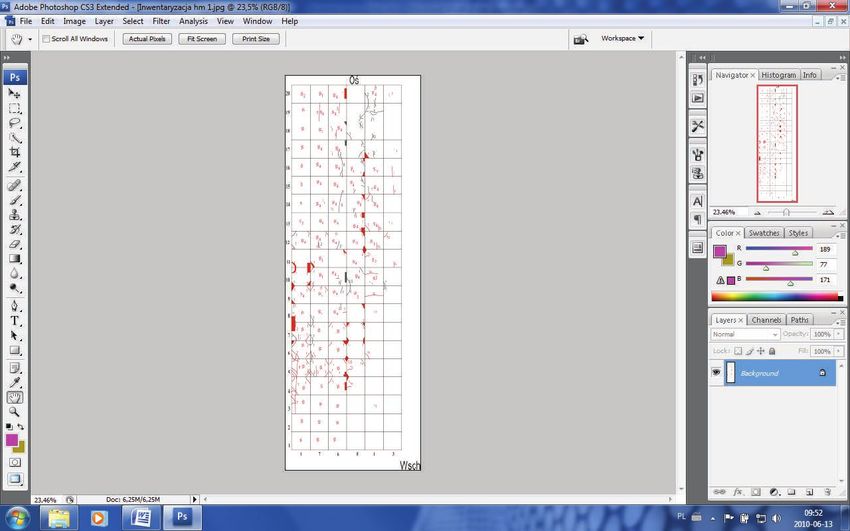
The Use Of Gis For The Technical Examination Of Take-Off Airport Road
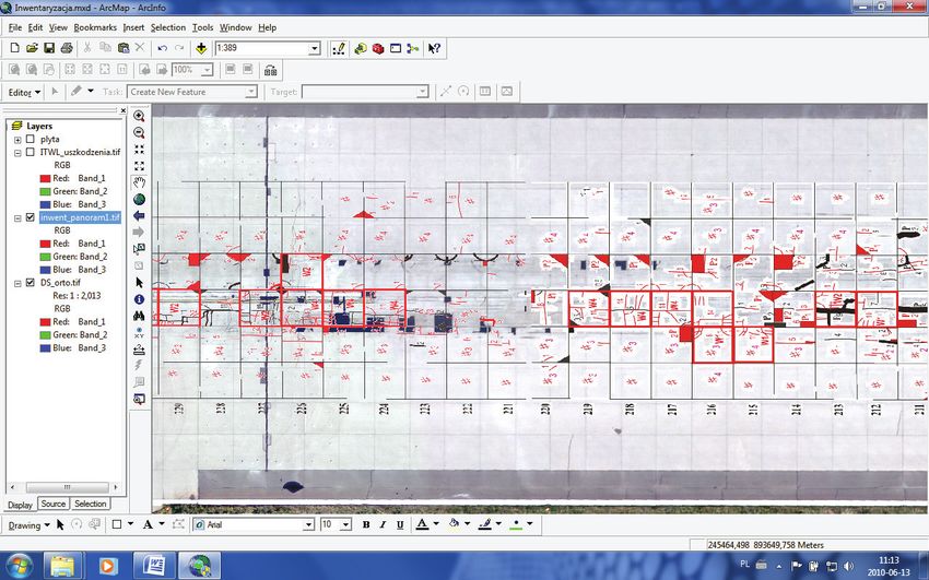
Fig. 1 One of the Air Force Institute of Technology (ITWL) studies used in the project.
constitute a separate element that would increase in time slab history was not created. However, I have concentrated
and become a history of repairs. Due to the limits connec- on the objective, i.e. proving the GIS project usefulness for
ted with the size of data I was able to input within the fra- runway condition control purposes. The list of attributes
mework of this project, an additional table with individual for traverses was discussed with the group of entities po-
tentially utilising the system.
Table 1. Damage Typology used
4. Undertaken Activities
Item Damage type
1. Exchanging worn expansion joints Map
2. Creating the expansion gaps
3. Considerable deterioration of slab load capacity
The following activities have been necessary to elabo-
SURFACE DAMAGES
rate the map:
4. Cavities
5. Surface peeling • review of the materials owned;
6. Netting of hair cracks on the surface • adapting the materials owned to one system, i.e.:
STRUCTURAL DAMAGES PUWG (Polish National Grid) 1965, zone V.
7. Cracks in slab corners
7.1 Local damage in slab corners; dimensions 5 x 5 cm - The local PUWG 1965 system was selected because it is
10 x 10 cm
Considerable damage of a slab corner; dimensions 0.5
the system for the geodetic centre in this area. Moreover, it
7.2 was assumed that it would be enough for such a small area,
x 0.5 – 1.5 x 1.5 m
8. Uncontrolled deep cracks in a slab i.e. 2 800 m long object. In order to transform this system
9. Slab edge damage
10. Slab sagging and faulting into WGS 2000, RTM measurements must be made.
Deep sinking slab degradation, numerous cross • During the next stage, the orthophotograph files un-
11. scratches on slabs, active cracks, cracks faulting under derwent pyramidisation and mosaicing to a single file.
load, chipping on the slab surface
12. Surface defect repair After completion of these activities the file has a very
large size, i.e. 2.82 GB.
6 Archives of Transport System Telematics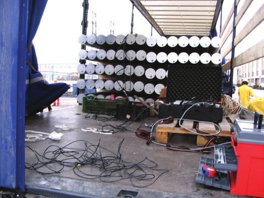
B. GRZĘDZIŃSKI

       Fig. 2. Defining the coordinate system for the project.

        • The graphic documentation elaborated by the Air For-             Taking into account the previously prepared bases, at-
          ce Institute of Technology does not depict the whole         tribute table and graphics, the traverse layer was created.
          runway in one image and has no georeferences. 24 files
          were “assembled” in Photoshop CS3 and the ArcInfo            Presentation
          georectification function was used in order to provide
          correct georeference data. The addition of georeferences         During the next stage, the method of data presentation
          to the study was problematic due to the fact that the size   was defined and, as a result, numbers of individual slabs
          of individual traverses does not reflect the actual appe-    are displayed on traverses.
          arance of slabs located in the runway. All slabs in the          Additionally, in order to ensure supervision over the
          Air Force Institute of Technology’s study are presented      slab condition, a different traverse colour code was assi-
          in a symbolic form and their size is 5 x 5 m. The ortho-     gned to each detailed slab condition attribute.
          photograph was used as the initial material for input-
          ting georeferences and, next, the accuracy of obtained
          compliance was checked by means of 10 field DGPS             5. Conclusion
          measurements. The ensured accuracy was defined as
          sufficient for further utilisation of the materials by the        The implemented project has satisfied the require-
          Airport Dispatchers Department which will plot the           ments determined in the initial part as regards the possi-
          information on the basis of devices with GPS accuracy.       bility of recording the runway condition.
        • Next, the transparency of the base of the layer elabora-          The ARC INFO tool made it fully possible to prepare
          ted on the basis of the Air Force Institute of Technolo-     the initial material for the project fulfilling the required
          gy’s study was set up.                                       functions as regards implementing changes, visual repre-
                                                                       sentation of the object condition and using the materials
       Database                                                        available in the airport resources.
                                                                            Following the material elaboration, it was consul-
           The Exel suite was used to create a table containing        ted with a group of potential users. On the basis of the
       attributes for target slab traverses. This table was inputted   consultations and arrangements, it has agreed that it is
       in ArcCatalog.                                                  necessary to complement the database with drop-down

Volume 4 • Issue 2 • May 2011                                                                                                         7
The Use Of Gis For The Technical Examination Of Take-Off Airport Road

    Fig. 3. Example of divergence of data obtained after superimposing the panorama of Air Force Institute of Technology’s
            graphic studies on the orthophotograph with georeferences

    Fig. 4. The same fragment of the runway after making a correction by means of a DGPS device.

8                                                                                       Archives of Transport System Telematics
B. GRZĘDZIŃSKI

       Fig. 5 Map fragment with record traverses, slab numbers and colour codes showing the damage degree

       lists in order to minimise the possibility of editing the        cameras, LIDAR, geodetic measurements, ground-pene-
       same statements with different expressions. Initially, 12        trating radar), determining priority activities and evaluate
       database components were defined and later 5 final ele-          the effectiveness of previously taken actions.
       ments vital for this task were selected. These elements
       are sufficient for the system to fulfil its function and limit
       the capacity required for database operation. Presently, if      Bibliography
       proper expenditures are ensured, it is possible to accele-
       rate the data input using an integrated system for mobi-         [1] LONGLEY P.A., GODCHILD M.F., MAGUIRE D.J.,
       le field scanning based on three LIDAR scanners, three               RHIND D.W. :GIS Teoria i Praktyka; PWN
       CCD cameras and ground-penetrating radar. This sys-              [2] HARVEY F. :A PRIMER OF GIS – Fundamental
       tem would make it possible to obtain data regarding the              Geographic And CARTOGRAPHIC CONCEPTS
       actual runway condition within 30 minutes. Taking into           [3] SHEKHAR S., XIONG H.: Encyclopedia of GIS;
       account the object type, the best device for collecting this         Springer Reference
       kind of data is a mobile platform for field scanning as ga-      [4] LUSCH D.P.: Fundamentals of GIS - Emphasizing
       thering this data from the air (flight) does not guarantee           GIS Use for Natural Resources Management
       the required quality o acquired data. Presently available        [5] GIS applied to administrative boundary design Ser-
       teledetection equipment support automatic recognition                ryn Eagleson; Department of Geomatic Faculty of
       of individual damages so, in near future, the process in-            Engineering; The University of Melbourne
       putting data should become much easier.                          [6] DEMARS M.N.: GIS For DUMMIES; Wiley Publi-
            As for now, the human eye is the best instrument to             shing,Inc.
       detect hair cracks caused by frost which are not detected        [7] WYATT P. AND RALPHS M.: GIS in Land and Pro-
       by automatic systems. On the other hand, only thanks                 perty Management; Spon Press
       to devices like ground-penetrating radars we are able to
       assess the condition of the runway substructure. The sys-
       tem presented in this paper makes it possible to efficien-
       tly analyse data acquired using a variety of methods (i.e.:
       employees’ field reports, data acquired from devices like

Volume 4 • Issue 2 • May 2011                                                                                                          9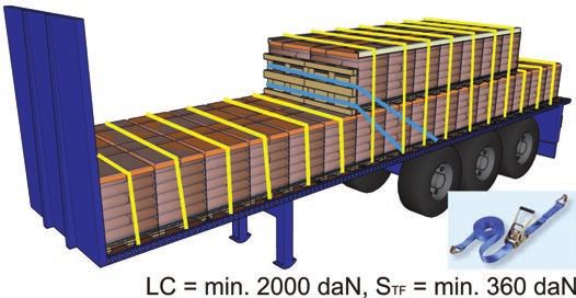
Archives of                                                                                      Volume 4

                               Transport System                                                                                Issue 2

                                 Telematics                                                                               May 2011

 Different measures for load securing
 create barriers in international road
           freight transport
              J. JAGELCAKa, J. GNAPa
              aDepartment   of Road and Urban Transport, Faculty of Operation and Economics of Transport and
               Communications, University of Zilina, Univerzitna 8215/1, 010 26 Zilina Slovakia
              EMAIL: juraj.jagelcak@fpedas.uniza.sk

              ABSTRACT
              The purpose of this article is to present measures related to the load securing on European level. The
              road transport plays significant role in Europe. With the increasing volume of goods carried by road
              the number of vehicles are increasing and also the number of accidents involving trucks. The appro-
              priate load securing increases the safety of road freight transport. European Best Practice Guidelines
              on Cargo Securing for Road Transport issued by European Commission are the first document on
              European level offering the load securing information.
              There is also a lack of load securing training for truck drivers in most of the EU member states. In most
              member states the load securing is not the part of the training to obtain truck driving licence. The di-
              rective 2003/59/EC on the initial qualification and periodic training of drivers of certain road vehicles
              for the carriage of goods or passengers shall improve the situation. The education of truck drivers from
              load securing began since September 2009.
              The standard EN 12195-1 offers calculation base to design load securing arrangements. There were
              cases when it has created unreasonable demands for load securing. The standard has been revised and
              finally published in May 2011. However, still the differences between the designs according to the EN
              12195-1, methods using in Nordic countries, Germany and according to the IMO/ILO/UN ECE Gu-
              idelines on packing of cargo transport units exists. European Best Practice Guidelines on Cargo Secu-
              ring for Road Transport are need to be revised to reflect the development in the area of load securing.

              KEYWORDS: load securing, road freight transport, safety action

         Road Safety Action Programme and Load Secu-                    These guidelines should be the help for legislation
     ring                                                           changes in most of EU member states with only gene-
         The traffic safety is crucial with the increasing number   ral and insufficient legislation (mainly the goal of le-
     of vehicles on European roads. The EU bodies monitor ac-       gislation is: the load may not endanger) covering load
     cidents in road transport and accept necessary measures        securing without methods how to achieve the goals of
     to achieve required level of safety. In terms of Road Safety   legislation including problems with load securing con-
     Action Programme the European Commission prepared              trols by authorities.
     European Best Practice Guidelines on Cargo Securing                Mr. Jacques Barrot, Vice-President of the European
     for Road Transport with the active participation of the        Commission, which was the Commissioner in charge of
     authors of this paper. [4]                                     transport introduces these guidelines and says:

10                                                                                © Copyright by PSTT , All rights reserved. 2011
J. JAGELCAK, J. GNAP
“It has been estimated that up to 25% of accidents discrepancy between the securing equipment specified
involving trucks can be attributable to inadequate cargo in the carriage order and equipment necessary to secure
securing. Rules on cargo securing exist in several Member the load correctly occurs. Here the carrier can relieve of
States, but they often differ in content and scope, making liability for correct load securing. There are also compa-
it very difficult for international transporters to know nies with internal load securing guidelines but presented
what the minimum cargo securing requirements are for a load securing is not efficient and road carriers refuse to
given cross-border transport operation.“ [4] secure the load according to these guidelines.
Faults usually occurred in traffic in relation to the Convention on the Contract for the International
load securing Carriage of Goods by Road (CMR)
Present situation in traffic shows that there are follo- This convention stipulates the responsibilities of the
wing mistakes usually occurred in traffic in relation to the parties participated in international carriage of goods by
loading and load securing. road.
The load carried in inappropriate vehicle is usual way According to Article 17:
how the load is carried. Usually the load does not fit to “1. The carrier shall be liable for the total or partial loss
the vehicle or the vehicle superstructure is not design for of the goods and for damage thereto occurring between the
blocking of load as it should be according to the EN 12642 time when he takes over the goods and the time of delive-
[22]. Typical example is the curtainsider semi-trailer with ry, as well as for any delay in delivery.”(Convention CMR,
sidewalls not designed for load securing. The load must 1956)
be lashed. However, if the load is not permitted to lash This means, if the carrier takes over the shipment, he
because of soft edges, than the vehicle is not suitable for also takes over the full responsibility for the shipment
transport. where load securing plays significant role to prevent any
The bad condition of the vehicle superstructure is the loss or damage on shipment. However, CMR Convention
second problem where structural faults or missing parts of doesn’t stipulate who is obliged to do the load securing.
the superstructures e.g. wooden laths exist. According to the Article 17 sec. 4: the carrier shall be
The lashing points on a platform are crucial if the cargo relieved of liability when the loss or damage arises from the
need to be lashed. Sufficient number, strength and position are special risks as according to the letter b) the lack of, or defec-
important. Standard EN 12640 [23] defines basic requirements tive condition of packing in the case of goods which, by their
but minimum 12 pairs of lashing points per 13,6 m length of nature, liable to wastage or to be damaged when not packed
semi-trailer does not fit to the 17 sections of pallets loaded. or when not properly packed.
Also minimum strength of 2000 daN is not suitable when
common lashing straps of lashing capacity 2000 or 2500 daN Responsibility of the driver for loading and secu-
are used more than one in same direction of load movement. ring of a cargo
Appropriate loading is crucial point how to load the In many EU countries the driver of the vehicle is usu-
vehicle safely and in easy way to secure and not to over- ally directly responsible for appropriate load securing in
weight. It there is a lot of space between the load units a way not to endanger traffic safety by the load on the ve-
then the load securing is difficult and costly. hicle. However, the driver meets a broad range of carrying
Load on open vehicles is clearly visible by all road goods and often doesn’t have sufficient information about
users. When the load is not secured, which is clearly the load parameters as the weight, the dimensions, the po-
seen, this is very dangerous to road users. On the other sition of the centre of gravity and behaviour of the load
hand, unsecured load in closed vehicles presents hid- during carriage. Sometimes he is not allowed to be present
den danger to the road users. during the loading and the vehicle is sealed after the lo-
Top-over lashing (tie-down) is the most frequent ading. The driver does not perform load securing.
lashing method but not suitable to secure heavy loads There is usually only general legislation defining the
not blocked forwards. When the load is settling the ef- goal – safety. But in many EU countries there is a lack of
fect of the tie-down is lost. Therefore retensioning rec- procedures to achieve the safety of a load. This means how
ommended by the EN 12195-1 is important [20]. to secure the load in a correct way. There are also excep-
The type and condition of securing devices plays im- tions in countries as Germany and Nordic countries with
portant role by load securing. Polyester lashing straps load securing legislation and standards with 30 years tra-
wear our more quickly than steel lashing equipment [18 ]. dition and also with effective load securing controls.
Manufacturing companies tend to save costs on The truck drivers in most of the EU countries have a
packing and the safety of the load has to be assured by minimum knowledge from the load securing because this
securing equipment provided by the carrier. Here the is not a part of the education to obtain a driving licence.
Volume 4 • Issue 2 • May 2011 11Different measures for load securing create barriers in international road freight transport
European Directive requiring education of profes- orientation of the packages or cause them to be damaged.
sional drivers from loading and securing of a cargo When dangerous goods are carried with other goods (e.g.
The European commission published the Directive heavy machinery or crates), all goods shall be securely fixed
2003/59/EC on the initial qualification and periodic or packed in the vehicles or containers so as to prevent the
training of drivers of certain road vehicles for the car- release of dangerous goods.
riage of goods or passengers to increase the traffic safety Movement of packages may also be prevented by filling
and the level of knowledge of professional drivers. The di- any voids by the use of dunnage or by blocking and bracing.
rective stipulates responsibility for EU member states to Where restraints such as banding or straps are used, these
create the system of the initial qualification of professional shall not be over-tightened to cause damage or deformation
drivers and periodic trainings. Knowledge from loading of the package (Guidance on the stowage of dangerous go-
and securing of a cargo is a part of the List of subjects in ods can be found in the European Best Practice Guidelines
ANNEX 1 of the directive 2003/59/EC as follows: on Cargo Securing for Road Transport published by the Eu-
“1.4. Objective: ability to load the vehicle with due re- ropean Commission. Other guidance is also available from
gard for safety rules and proper vehicle use: competent authorities and industry bodies.). [2]
forces affecting vehicles in motion, use of gearbox ra-
tios according to vehicle load and road profile, calculation Load securing guidelines for road transport
of payload of vehicle or assembly, calculation of total Even if the professional driver has general knowledge
volume, load distribution, consequences of overloading about loading and load securing still there are organisa-
the axle, vehicle stability and centre of gravity, types of tions distributing specific load requiring special securing.
packaging and pallets; Some organisations solve this problem by internal load
main categories of goods needing securing, clamping securing guidelines. They offer basic aid for drivers and
and securing techniques, use of securing straps, checking loading staff. These organisations lay stress on work sa-
of securing devices, use of handling equipment, placing fety. Mainly they define priorities: „superior product
and removal of tarpaulins.“ (Directive 2003/59/EC) requires superior carriage and the customer needs our
In order to establish that the driver complies with the product damage free and in time“. The sender should
obligations of the directive, Member States should issue also specify load securing aids the carrier should have and
the driver with a certificate of professional competence. the aids there are available for the carrier at the loading
Member States shall apply these measures from 10 Sep- site. He should choose the right vehicle, correctly perform
tember 2009 as regards the initial qualification required the loading and offer specific load securing aids. Usually
to drive vehicles in licence categories C1, C1+E, C and the responsibility of the driver is to distribute the load in
C+E. regard to axle loads and secure it with the close coopera-
The general aim specified by the directive must be tion of the sender.
more specified in national teaching syllabuses for load se- The driver must be aware of the load carried e.g. in
curing. European Best Practice Guidelines ([4] sec. 8.14) case the load settles he checks the tension in lashings
also specifies the content of the load securing training. and retighten them during carriage.
In table 1 there are companies in Slovakia with Load
Loading and securing of dangerous goods Securing Guidelines for Road and Sea carriage. The
By transport of dangerous goods significant measures Department of Road and Urban Transport, University
are taken in Europe because these goods are danger for of Zilina worked up the guidelines for their load based
health and life of the persons, animals and plants or for on calculations and tests in years 2007 -2011.
the environment. This is covered in Europe by European In table 2 there are load securing situations of dange-
Agreement Concerning the International Carriage of rous palletized goods in five cargo transport units for road
Dangerous Goods by Road – ADR Agreement. and sea transport according to the load securing guide-
Part 7.5.7 Handling and stowage describes general re- lines of one chemical company in Slovakia distributing
quirements for securing of dangerous goods: these goods on trailers in Europe and in containers world
„7.5.7.1 Where appropriate the vehicle or container shall wide. The stowage and the type of cargo transport unit
be fitted with devices to facilitate securing and handling of have significant influence on load securing inside the unit.
the dangerous goods. Packages containing dangerous sub- Also the type of packaging plays important role to fit well
stances and unpackaged dangerous articles shall be secured into the cargo transport unit. [19]
by suitable means capable of restraining the goods (such Load securing controls
as fastening straps, sliding slatboards, adjustable brackets) Even if the directive 93/59/EC and the system of
in the vehicle or container in a manner that will prevent the education of professional drivers bring a general
any movement during carriage which would change the knowledge of loading and load securing there is still
12 Archives of Transport System TelematicsJ. JAGELCAK, J. GNAP
Table 1. Load securing guidelines prepared in Slovakia – 2007 - 2011 Table 2. Loading and securing of palletized cargo loaded in two
layers – upper layer incomplete in different cargo transport
units in one company according to the Load securing
Measurement of coefficients
Calculation of load securing
of static friction performed
arrangements performed
Static inclination tests
guidelines
Dynamic driving tests
performed
performed
Company
Number of
Type of load distributed Cargo transport pallets Transport Load securing aids
unit Weight mode
of the load
2x europallet
Semi-trailer with 11x web-lashing
46 pallets Road
sideboards with tensioner
22 tones transport
Steel (cf. Figure 1) 2x long corner
• sheets protectors
›› bundles
1 YES NO NO NO
›› coils Semi-trailer open 2x europallet
›› coil-strips 46 pallets Road
or curtainsider 18x web-lashing
• pipes 22 tones transport
(cf. Figure 2) with tensioner
Steel
• profiles packed in bundles Curtainsider
2 ›› square profile YES YES YES NO certified according 2x europallet
›› rectangular profile 46 pallets Road
to EN 12642 Code 6x web-lashing with
›› circular profile 22 tones transport
XL tensioner
Paper (cf. Figure 3)
• sheets
3 ›› A4, A3 office paper YES NO NO NO
›› offset paper
• reels
Aluminium
• extrusion billets
›› long extrusion billets
4 ›› short extrusion billets YES YES YES YES
• ingots
Chemical cargo
• dangerous goods packed in big-bags
Chemical cargo – dangerous goods
• bags on a pallet stabilized by a foil
5 • big-bags YES YES YES YES
• Steel drums
• Intermediate Bulk Container
Copper
• wire
• anodes in bundles
6 Chemical cargo – dangerous goods YES YES YES NO
• bags on a pallet stabilized by a foil Fig. 2. Load securing of palletised load in open semi-trailer or
• big-bags curtainsider (cf. Table 2)
Fig. 1. Load securing of palletised load in semi-trailer with Fig. 3. Load securing of palletised load in curtainsider certified
sideboards (cf. Table 2) according to the standard EN 12642 Code XL (cf. Table 2)
Volume 4 • Issue 2 • May 2011 13Different measures for load securing create barriers in international road freight transport
How many lashing aids do we need, is often a big is-
sue when it comes to cargo securing. There are met vari-
ous demands for cargo securing in European countries.
The demand for the number of lashings is really confusing
for international road haulers. The lorry driver travelling
through different countries of Europe is often afraid of
how many lashing straps or other equipment the control-
ling authorities and consignors at loading sites will want
to see and if the straps are proper to use and fulfil the de-
mands of standards or guidelines.
Top-over lashing, as the most frequent lashing
Fig. 4. Results from survey among 55 transport and distribution method
companies in Slovakia in 2005 Top-over lashing is used everywhere when it comes
to cargo securing by lashing. If the driver secures general
load by lashing he uses top-over lashing in about 90 % of
all cases. The results from survey among 55 transport and
distribution companies in Slovakia in 2005 are showed in
the figure 4.
But what the effectiveness of top-over lashing is each
driver must take into consideration. The driver should
know what the friction and acceleration are and he also
should know that usually the force on the opposite side
without a tensioner is lower when compared to the tensio-
ner side [6] , [8], [10].
Variation of tension forces during real tensioning of
the usually used web-lashing by a ratchet tensioner is
shown in the figure 5.
F1…force on tensioner side, F2…force on opposite
side without tensioner, SHF – standard hand force of 50
Fig. 5. Variation of tension forces during ratchet tensioning for top- daN applied on hand of the ratchet [8], [16]
over lashing with tensioner placed on side of the load It is clearly seen the force increase during tension-
ing. The numbered force peaks present the tightening
a lack of base how to design and perform the load se- through the teeth of the ratchet spindle. It is also seen
curing and how to check it by controlling authorities. that the force on the tensioner side (F1) is higher than
Germany and Sweden have well trained inspectors to the force on the opposite side (F2). This force differ-
perform load securing checks. The problem is that ence depends on corner friction. If the corner friction
“sufficient load securing” is different in Sweden and is low the forces are almost equal. In some cases when
Germany and according to the EN 12195-1:2011. The the opposite line do not slip back during the tensioning
level of load securing is different. The Czech Repu- the F2 > F1.
blic started to perform controls according to the EN
12195-1:2011 since 1st of July 2011. Main views on load securing in EU
Sec. 8.14 of European Best Practice Guidelines also Friction and forces in top-over lashing are the main
specifies that: points influencing top-over lashing and these points cre-
“It is recommended that road side checks are carried out ate controversy between the standard EN 12195-1 Load
using the same standards which are used for training for driv- restraint assemblies on road vehicles – Safety - Part
ers and other staff. Road side checks should be carried out 1: Calculation of lashing forces and IMO/ILO/UN
by specifically trained staff. All members of enforcement bod- ECE Guidelines for packing of cargo transport units
ies concerned with traffic supervision should receive at least (CTU’s) which are the two main basis for load securing
training about the basic issues of cargo securing, as mentioned design in Europe. The discussion was opened during the
above. Staff members carrying out dedicated supervision work on European Best practice guidelines on cargo
measures for heavy goods vehicles should be trained as ex- securing for road transport and led after some years to
perts also in all the other fields mentioned above.”[3] the revision of European standard EN 12195-1 which has
14 Archives of Transport System TelematicsJ. JAGELCAK, J. GNAP
Table 3. Basic parameters to design cargo securing arrangements
CTU Guidelines Standard
Parameter Standard EN 12195-1:2004
IMO Model course 3.18 EN 12195-1:2011
Acceleration coefficients
Road transport – forwards - cx 1g 0.8 g 0.8 g
Road transport 0.5 g 0.7 g 0.6 g
tilting sideways - cy
Friction for frictional lashing method
friction parameter– m static - mS dynamic - mD 0.925 × mS
Friction for direct lashing methods
m × fm fm = 0.7 fm = 0.7 fm = 0.75
k – factor for frictional lashing with 1 tensioner only
k-factor 2 1.5 2
Safety factor for frictional lashing - fS
1.1
fS 0 0 1.25 only road transport
forwards
Static inclination tests and dynamic driving tests as an equal measure for cargo securing arrangements as theoretical
calculations based on load and transport types
YES–stat. ; NO–dyn. NO YES
Frictional lashing against sideways tilting
FT…tension force in the lashing line, STF = standard tension force based on measurement procedure, LC…lashing capacity
MAXIMUM FROM
Equations calculate with cy = 0.5 cy = 0.7 cy = 0.5 ; FT = STF
following parameters FT = STF FT = STF OR
cy = 0.6 ; FT = ½ LC
Frictional lashing against sideways tilting for rows of identical units
NO the same equation as for
Equations YES - tables YES
one unit
Equations for loop lashings and spring lashing
NO – the same equation as for
Equations YES - tables YES
slope and diagonal lashings
Defined measurement procedures to obtain static and dynamic friction coefficients
YES – static
YES - static YES
NO - dynamic
Friction value for sawn wood – fabric base laminate/plywood
m mS = 0.5 ; mD = 0.35 mS = 0.5 ; mD = 0.35 m = 0.45
been successfully revised. The standard is, as national means that on the side without a tensioner there is only
standards, implemented in EU but not obligatory in all half of the force of the tensioner side. Of course, this
the member states. In several states the standard is only value is very conservative and measurements showed
on a voluntary base (in Czech republic obligatory since that also the values more than 2 are possible to meas-
1st of January 2011, in Germany since is valid). The dis- ure. The value of k-factor mainly depends on the corner
cussions of experts showed that the standard stipulates friction. [10]
very high and costly demand on cargo securing when it The issue is clear. The use of k-factor lower than 2
comes to top-over lashing. Therefore it has been called influences the number of lashings. The situation in EN
for the revision. 12195-1:2004 led also to infinite number of lashings for
The main points of discussions were about fric- top-over lashing of unstable loads against tipping. [17]
tion (static or dynamic), acceleration sideways and The following table gives basic design parameters ac-
k-factor. K-factor was always the biggest problem dur- cording to the CTU Guidelines, the standard EN 12195-
ing the discussions. The standard defines it as the “co- 1:2004 and the new standard EN 12195-1:2011.
efficient which allows for the loss of tension force due
to friction between lashing and load”. (Standard EN Monitoring of shipments
12195-1:2004) [8] To monitor the accelerations during carriage various
Because of the friction on the corners the force on monitoring devices are available where accelerations in
the opposite side is usually lower then the force on the three axis and rotations are recorded together with GPS
tensioner side. This is presented in the calculation by position, speed and climatic conditions. This equipment
k-factor with value 1,5 for top-over lashing with a ten- can also be used during dynamic driving tests of load se-
sioner on one side of the lashing only. The value 1,5 curing (cf. Fig. 6).
Volume 4 • Issue 2 • May 2011 15Different measures for load securing create barriers in international road freight transport
Conclusion Bibliography
The Directive 2003/59/EC on the initial qualification and [1] Convention on the Contract for the International
periodic training of drivers of certain road vehicles for the Carriage of Goods by Road (CMR) (United Nations
carriage of goods or passengers is applied in all member sta- Economic Commission for Europe, 1956, 1978)
tes for truck drivers from September 2009 but not at the same [2] European Agreement Concerning the International
level. There must be national teaching syllabuses reflecting Carriage of Dangerous Goods by Road – ADR Agre-
current demands on load securing. The different demands on ement (United Nations Economic Commission for
load securing means also the training and controls are per- Europe, Committee on Inland Transport, 2011)
formed in different way in member states. For international [3] European Best Practice Guidelines on Cargo Securing
road freight transport and multimodal transport it is necessa- for Road Transport (European Commission, Directora-
ry to unify EU requirements on load securing. te-General for Energy and Transport, Road Safety Unit,
These means the drivers should be educated accor- Brussels 2007. )
and use them in EU. Here teaching sylabusses must reflect [4] European best practice guidelines on cargo securing for
the results of securing methods according to the IMO/ road transport - Online document. - [Brussels : Euro-
ILO/UN ECE Guidelines on Cargo Transport Units, EN pean Commission, Directorate-General for Energy and
12195-1:2011 and German guidelines VDI 2700. Transport], 2006. - 208 s. - [Authors: Andersson Peter,
European Best Practice Guidelines are need to be Arbaiza, Alberto ; Bonnet, Géraldine ; Charalampopo-
updated according to the EN 12195-1:2011 because the ulos, George ; Finn Engelbrecht, Ruby ; Hassing, Sibrand
current specification of load securing design is not valid ; Jagelčák, Juraj ; Jonckheere, Filip ; Kolettas, Soteris ; Ku-
anymore. It Germany wants also to specify the calculation usk, Harri ; Kärki, Esko ; Linssen, Hubert ; Lundqvist,
results in the guidelines according VDI 2700 Sheet 2 than Anders ; Manolatou, Eleni ; Martins, João ; Nordström,
these option should be also taken into consideration. Rolf ; Pompe, Julie ; Procházka, Miloš ; Renier, Luc ; Roc-
co, Luca ; Rolland, Nathalie ; Ruzgus, Gintautas ; Schoofs,
Acknowledgements Cyriel ; Siegmann, Ernst Otto ; Surmont, Charles ; Vaik-
This contribution is the result of the project implemen- maa, Siim ; Vaitužs, Zulizs ; Van Praet, Willy ; Verlinden,
tation: Centre of excellence for systems and services of Jos ; Wiltzius, Marc ; Winkelbauer, Martin ]
intelligent transport, ITMS 26220120028 supported by [5] Directive 2003/59/EC on the initial qualification and
the Research & Development Operational Programme periodic training of drivers of certain road vehicles
funded by the ERDF. „Podporujeme výskumné aktivity for the carriage of goods or passengers (European
na Slovensku/Projekt je spolufinancovaný zo zdrojov EÚ“ Parliament and the Council)
[6] DÄNEKAS, R. (2007) Expert’s report prepared on
the issue: When lashing down, is the pretension for-
ce, which is applied on the ratchet side, being redu-
ced by friction in the area of the respective deflection
leading to a lower pretension force of the side (loose
end) that is opposing the ratchet (Von der Industrie
und Handelskammer zu Aachen Öffentlich Bestel-
lter und Vereidigter Sachverständiger für Ladungs-
sicherung und Anschlagtechnik im Landverkehr,
Document CEN/TC 168/WG 6 N 219)
[7] JAGELČÁK, J.:Top-over lashing securing the load
against tipping, equation (8) of the standard EN
12195-1 stipulates infinite number of lashings for
specific lashing angles (University of Zilina, De-
partment of Road and Urban Transport, Document
CEN/TC 168/WG6 N 180, CEN 13.12.2006)
[8] JAGELČÁK, J.: Tension forces in top-over lashing & k-
factor theoretical explanation and practical results (Uni-
Fig. 6. Dynamic driving tests of load securing of aluminium extrusion versity of Zilina, Department of Road and Urban Trans-
billets using monitoring equipment port, Document CEN/TC 168/WG 6 N 191, 2.1.2007)
16 Archives of Transport System TelematicsJ. JAGELCAK, J. GNAP
[9] JAGELČÁK, J., ANDERSSON, P.: Calculation of re- [18] JAGELČÁK, J., ANDERSSON, P.: Report from pul-
quired number of top-over lashings for sliding and ling tests with used lashing equipment - Online -
tilting sideways with different input data (MariTerm [Höganäs : MariTerm AB], 2009. - 52 pages, [Co-au-
AB, document CEN/TC 168/WG 6 N 209, 22.5.2007) thors: Lind, Elise ; Petersen, Sven Sökjer ] - http://
[10] PETERSEN, S.S. Practical tests of pretension ability www.mariterm.se/hoganas/rapporter.html
(MariTerm AB. Document CEN/TC 168/WG 6 N [19] JAGELČÁK, J.: Balenie a upevnenie nákladu pre
174), (2006) paletizovaný nebezpečný náklad prepravovaný cest-
[11] STN EN 12195-1:2004 Load restraint assemblies. Sa- nou, železničnou a námornou dopravou. In: Dopra-
fety. Part 1: Calculation of lashing forces va a spoje - ISSN 1336-7676. - 2010. - Č. 1 (2010), p.
[12] IMO/ILO/UN ECE Guidelines for Packing of Car- 107-114.: http://www.fpedas.uniza.sk/dopravaaspo-
go Transport Units (CTUs) (International Maritime je/2010/1/jagelcak.pdf
Organization, London, 1997, ISBN 92-801-1443-3) [20] JAGELČÁK, J. SKRÚCANÝ,T.: Prečo doťahovať po-
[13] Safe Packing of Cargo Transport Units (CTUs) – CO- pruhy,. In: Truck & business : štvrťročník pre stra-
URSE, Model course 3.18 (International Maritime tégiu podnikania v cestnej doprave. - ISSN 1337-
Organization, London, 2001, ISBN 92-801-5116-9) 897X. - Roč. 3, č. 4 (2010), s. 36-37.
[14] Safe Packing of Cargo Transport Units (CTUs) – [21] JAGELČÁK, J.: Zvýšenie kvality a bezpečnosti cestnej
WORKING BOOK with quick lashing guides for nákladnej dopravy z hľadiska upevňovania nákladu
transport on road and in sea areas A, B, & C, Model [dissertation thesis]; supervised by Jozef Gnap. - Ži-
course 3.18 (International Maritime Organization, linská univerzita v Žiline, Fakulta prevádzky a eko-
London, 2001, ISBN 92-801-5127-4) nomiky dopravy a spojov, Katedra cestnej a mestskej
[15] STN EN 12195-1:2011 Load restraint assemblies on dopravy - ČVO 37-01-9. - Žilina : [s.n.], 2007. - 116
road vehicles – Safety – Part 1: Calculation of secu- pages
ring forces [22] EN 12642:2006 L & XL: Securing of cargo on road
[16] JAGELČÁK, J., RIEVAJ, V.: Standard tension for- vehicles - Body structure of commercial vehicles -
ce : tension forces in web-lashing for load securing Minimum requirements
created by a ratchet tensioner [Normálna napínacia [23] EN 12640:2001: Securing of Cargo on Road Vehicles.
sila. Napínacie sily v popruhu pre upevnenie nákladu Lashing Points on Commercial Vehicles for Goods
vyvolané napínačom s rohatkou a západkou] - [1st Transportation: Minimum requirements and testing
ed.]. - Köln : Lambert Academic Publishing AG &
Co. KG, 2009. - 79 s., AH 6,.50 : obr., tab. - ISBN 978-
3-8383-1817-2
[17] JAGELČÁK, J.,: Equation of the standard EN 12195-
1 stipulates unreasonable demands for cargo secu-
ring. In: Communications : Scientific Letters of the
University of Žilina. - ISSN 1335-4205. - Vol. 9, No.
4 (2007), pp. 30-33.
Volume 4 • Issue 2 • May 2011 17Archives of Volume 4
Transport System Issue 2
Telematics May 2011
Structure of interlocking table
M. JURCZAK
Faculty of Transport, Silesian University of Technology, Krasińskiego 8/201, 40-019 Katowice,
Poland,
EMAIL: jurczak.mateusz@tlen.pl
ABSTRACT
The topic of the article is to present performance of interlocking table. It has to bring nearer this pro-
blem. There are many different solutions in making of project tables. In the future it should be done
more clearly to make work time shorter and project cheaper. In first part of the article there is model
illustrative structure of interlocking table creation along with definitions. The second part of the article
shows more detailed information about train route, which is closely connected to the topic of this pu-
blication. In the next part there is suggestion of model for route realization along with elements which
participate in this global system. At the end of the article there is scheme of fictitious railway station as
well as variations described with the benefit of contradictious and locking tables
KEYWORDS: interlocking table, rail safety
The interlocking table consists of upper part, with
1. Introduction heading of table and lower part, with closing table. The
heading of interlocking table states type and quantity of
The aim of the article is to present performance of in- internal, adjustable and block controls. On the other hand,
terlocking table. It has to bring closer this problem. There closing table indicates point locks and mutual interactions
are many different solutions in making this king of project between controls [1].
tables. In the future it should be done more clearly to make The structure of interlocking table indicates Figure 1.
work time shorter and project cheaper. In first part of the
article there is exemplary illustrative structure of interloc-
king table creation along with definitions. The second part 2. Train routes
of the article shows more detailed information about train
route, which is closely related to the topic of this publica- The basic point, from which should be started creation
tion. In the next part there is suggestion of model for route of interlocking table is construction of project documen-
realization along with elements which participate in this tations. It should be consistent with standards (norms)
global system. At the end of this article there is scheme and railway instructions. Among many others, here can
of fictitious railway station as well as variations described be included for example documentation of internal devi-
with the benefit of contradictious and locking tables. ces (systems), which is part of larger ventures such as line
The interlocking tables are designed for controls clear block, level crossing or even interlocking systems. The key
performance, which is included on train and manoeuvre part, which is the foundation of whole interlocking table is
routes. They are created on basics of railway station’s sche- of course schematic plan of control devices.
matic plan and they are part of project’s documentation. The schematic plan – is created on the basic of layout
Tables are designed, especially in situations, when dispat- plan of railway track system. There is presented layout of
chers need to decide by themselves about letting train go railway tracks and crossings in contaminated scale (lon-
e.g. on replace signal. gitudinal 1:2000, transversal 1:500) and there are marked
18 © Copyright by PSTT , All rights reserved. 2011M. JURCZAK
Fig. 1. The structure of creation interlocking table
railway control devices and routes of trains. It is allowed to As a railway route can be understood – states set in or-
apply different scale [1]. der, in which should be found elements of controls, which
The next stage is creation of interlocking table for each are used to control railway traffic. They adjust, protect,
specific station, however it is important to remember abo- and control define train route [2].
ut limitations, which are results of the following: There are two types of railway routes, which needs to
• the depreciated speed, when train rides on hardened be taken into consideration in interlocking table:
point in position minus or of a set of facing point • train route – this is route, which describes train’s road [1]
• distances between signals and other controls, which • manouvre route – this route is set up for manoeuvring
are shorter than usually vehicles [1]
• lengthened safety road behind the semaphore
Main rules of train routes are as following:
These as well as other cases, must be analyzed and in- • train route has to be restrainted and after this process
terpreted from safety point of view. Besides, depending on there is no possibility to change state of elements, besides
needs, designers can decide about sense of railway routes changing outgoing signaling device from green to red
existence. • restraint of route can be half-open:
According to Figure 1, interlocking tables consist of automatically – after driving through the last point,
two main parts: which is on the way of train
• contradictions table (with contradictions routes) by personnel:
• closing table of railway interlocking devices. ›› immediately, regardless of route occupancy, with re-
gistration of this action;
The Contradictions table contains: rows and columns, ›› with time delay (90-120 seconds), however process
which describe all possible routes that are implemented as of slowing down must be stopped automatically,
well as variations between them. As variations, can be un- when rolling stock takes over the route of train
derstood cases, when routes exclude one another through: • restraint track can be divided on sections restraints si-
Various positions of controls in train routes multaneously with whole route, but still slowing down
• overlap in some parts of train route must be performed individually according to first point
• converge of safety road along with train road, except • in some systems used to control railway traffic, closure
route without stopping. of route can be initial phase in process of restraint.
Volume 4 • Issue 2 • May 2011 19Structure of interlocking table
• tracks without stopping should be held:
›› on main running routes 3. Example of route
›› on additional running routes, if system of controls
is adjusted to it
implementation model
›› on routes equipped with controls, which have con- Following rules from previous chapter, the model,
trol system measuring track occupancy. which describes train’s routes and manoeuvring routes
(from variation point of view) can be created. Additionally
Main rules of railway traffic, connected with manoeu- correct implementation of both routes (set up and restra-
vring routs are following [1]: int) can be performed as well as switching on permissive
• manoeuvring routes, not necessarily must have safety signal on semaphore can be done.
way and side guard To begin with, all controllers, which have influence on
• manoeuvring routes can be divided into: correct performance of route realization have to be speci-
›› organized – depending on type of controls, can be fied. For train routes there are controls as following:
closed or restrained. Routes like these should have • Z – points and derail:
permissive signal dependency, which would allow ›› ZP - in train road
to restrain or close specific elements of train routes, ›› ZO - in safety road.
›› unorganized – restrain or closure of railroad points The most important are following attributes: position
as well as exclusion of conflicting routes with other plus, position minus, out of control, stopping etc.
manoeuvres are not required
• in manoeuvring routes can apply układową control • S- signals in train road and side safe for routes:
niezajętości drogi jazdy and period of rozjazdu; ›› SP - train semaphores
• releasing routes can be performed: ›› SM - manoeuvre semaphores.
›› automatically after fulfilling conditions the same as The most important are following attributes: signal on
for train routes the semaphore, burned of the red light, out of control etc.
›› by railway personnel:
›› with registration of this actions for restrained • W- derails:
routes ›› WP - In train road
›› without registration for closed routes ›› WO - In safety road.
• it is recommended to use closed manoeuvring routes, The most important are following attributes: position
released automatically. plus, position minus, out of control, stopping etc.
Above rules are key with correct indication of varia- • I- isolated sections:
tions: ›› IT - track section
• conflicting routes as a result of various controls ›› IZ - point section.
position (points and derailers) The most important are following attributes: occupied,
• the same routes out of control, stopping etc.
• routes specially excluded.
• B- line blocks:
When it comes to closures, designers use also the fol- ›› BS - automatic line blocks
lowing remaining rules, which relates for instance to: de- ›› BP - semi-automatic line blocks
railing routes and specific descriptions: ›› BZ - telephone announcing.
• primary position (in plus) for point and derailer The most important are following attributes: auto-
• reversed position of point and derailer matic route through the station, states of block which are
• adequately wrote out isolated sections and controlled inform about the first block signal and occupy sections,
points way of block etc.
›› on train’s road
›› on safety way or crossover • P- level crossings:
›› on safety side
• routes depending on route Crucial are displays of signals on road signalling de-
• linear blocks – for all exits from railway station vices, lowering crossing gates and restraint in closed posi-
tion. Depending on to which category those crossings can
In manoeuvring routes, not necessarily have to be con- be allocated, restraint as well as closure can be realized au-
trols (systems) described in points from c to e. tomatically or manually by the gateman or by dispatcher.
20 Archives of Transport System TelematicsYou can also read