UNIFIED FACILITIES CRITERIA (UFC) ARCHITECTURE - UFC 3-101-01 16 December 2020 Change 1, 5 January 2021 - Whole Building ...
←
→
Page content transcription
If your browser does not render page correctly, please read the page content below

UFC 3-101-01
                                              16 December 2020
                                        Change 1, 5 January 2021

UNIFIED FACILITIES CRITERIA (UFC)

              ARCHITECTURE

   APPROVED FOR PUBLIC RELEASE; DISTRIBUTION UNLIMITED
UFC 3-101-01
                                                                      16 December 2020
                                                                Change 1, 5 January 2021

                         UNIFIED FACILITIES CRITERIA (UFC)

                                     ARCHITECTURE

Any copyrighted material included in this UFC is identified at its point of use.
Use of the copyrighted material apart from this UFC must have the permission of the
copyright holder.

Indicate the preparing activity beside the Service responsible for preparing the document.

U.S. ARMY CORPS OF ENGINEERS

NAVAL FACILITIES ENGINEERING SYSTEMS COMMAND (Preparing Activity)

AIR FORCE CIVIL ENGINEER CENTER

Record of Changes (changes are indicated by \1\ ... /1/)

 Change No.      Date             Location
 1               1/5/2021         2-4.3 1407.7.1 ccr 9099; 3-2 ccr 9208; 3-3 ccr 8235 and
                                  8541; 3-6.2 ccr 9570

This UFC supersedes UFC 3-101-01, dated 28 November 2011, with Changes 1-5,
dated 25 September 2019.
UFC 3-101-01
                                                                         16 December 2020
                                                                   Change 1, 5 January 2021

                                         FOREWORD

The Unified Facilities Criteria (UFC) system is prescribed by MIL-STD 3007 and provides
planning, design, construction, sustainment, restoration, and modernization criteria, and applies
to the Military Departments, the Defense Agencies, and the DoD Field Activities in accordance
with USD (AT&L) Memorandum dated 29 May 2002. UFC will be used for all DoD projects and
work for other customers where appropriate. All construction outside of the United States is
also governed by Status of Forces Agreements (SOFA), Host Nation Funded Construction
Agreements (HNFA), and in some instances, Bilateral Infrastructure Agreements (BIA).
Therefore, the acquisition team must ensure compliance with the most stringent of the UFC, the
SOFA, the HNFA, and the BIA, as applicable.
UFC are living documents and will be periodically reviewed, updated, and made available to
users as part of the Services’ responsibility for providing technical criteria for military
construction. Headquarters, U.S. Army Corps of Engineers (HQUSACE), Naval Facilities
Engineering Command (NAVFAC), and Air Force Civil Engineer Center (AFCEC) are
responsible for administration of the UFC system. Defense agencies should contact the
preparing service for document interpretation and improvements. Technical content of UFC is
the responsibility of the cognizant DoD working group. Recommended changes with supporting
rationale may be sent to the respective DoD working group by submitting a Criteria Change
Request (CCR) via the Internet site listed below.
UFC are effective upon issuance and are distributed only in electronic media from the following
source:
   • Whole Building Design Guide web site http://www.wbdg.org/ffc/dod.
Refer to UFC 1-200-01, DoD Building Code, for implementation of new issuances on projects.
AUTHORIZED BY:

  CHRISTINE T. ALTENDORF, PhD,                   R. DAVID CURFMAN, P.E., SES
  P.E., SES                                      Chief Engineer
  Chief, Engineering and Construction            Naval Facilities Engineering Systems Command
  U.S. Army Corps of Engineers

  NANCY J. BALKUS, P.E., SES                     MICHAEL McANDREW
  Deputy Director of Civil Engineers             Deputy Assistant Secretary of Defense
  DCS/Logistics, Engineering &                   (Construction) and Acting Deputy Assistant
  Force Protection (HAF/A4C)                     Secretary of Defense (Housing) Office of the
  HQ United States Air Force                     Assistant Secretary of Defense (Sustainment)
UFC 3-101-01
                                                             16 December 2020
                                                       Change 1, 5 January 2021
                         UNIFIED FACILITIES CRITERIA (UFC)
                         [NEW][REVISION] SUMMARY SHEET

Document: UFC3-101-01, Architecture

Superseding: UFC 3-101-01, dated 28 November 2011, with Changes 1-5, dated 25
September 2019

Description: This UFC unifies the architectural criteria for DOD. The format is updated
to the standard format of the Criteria Standard Format for all UFC.

Reasons for Document:
   •   Required update cycle

   •   Approved Criteria Change Request (CCRs)

   •   Conform the format to the UFC 1-300-01 Criteria Format Standard including
       alignment of requirements with the International Building Code (IBC).

   •   Incorporate latest technologies, policies and references

Impact: Improved mission capability through:
   •   Reduced total ownership costs of buildings through corrosion resistant design
       requirements

   •   Use of reference model codes to greatest extent possible

   •   Unification of service requirements

Unification Issues
   •   Referenced space planning criteria is contained in service specific publications.

   •   Service differences in Air Barrier Testing criteria are noted in this UFC.
UFC 3-101-01
                                                                                         16 December 2020
                                                                                   Change 1, 5 January 2021
                                           TABLE OF CONTENTS

CHAPTER 1 INTRODUCTION ....................................................................................... 1
   1-1            PURPOSE AND SCOPE. .......................................................................... 1
   1-2            APPLICABILITY. ....................................................................................... 1
   1-3            GENERAL BUILDING REQUIREMENTS. ................................................ 1
   1-3.1             Environmental Severity and Humid Locations. ...................................... 1
   1-4            BACKGROUND. ....................................................................................... 1
   1-5            OVERVIEW OF THIS UFC. ....................................................................... 2
   1-6            CYBERSECURITY. ................................................................................... 3
   1-7            ADDITIONAL REQUIREMENTS. .............................................................. 3
CHAPTER 2 MODIFICATIONS TO THE IBC ................................................................. 5
   2-1            CHAPTER 7 – FIRE AND SMOKE PROTECTION FEATURES. .............. 5
   2-1.1             SECTION 721 - PRESCRIPTIVE FIRE RESISTANCE.......................... 5
   2-1.2             SECTION 722 - CALCULATED FIRE RESISTANCE. ........................... 5
   2-2            CHAPTER 8 – INTERIOR FINISHES. ....................................................... 5
   2-2.1             SECTION 802 GENERAL. ..................................................................... 5
   2-3            CHAPTER 12 – INTERIOR ENVIRONMENT. ........................................... 5
   2-3.1             SECTION 1202 – VENTILATION. ......................................................... 5
   2-3.2             SECTION 1206 - SOUND TRANSMISSION.......................................... 5
   2-4            CHAPTER 14 – EXTERIOR WALLS......................................................... 9
   2-4.1             SECTION 1401 – GENERAL. ................................................................ 9
   2-4.2             SECTION 1404 - INSTALLATION OF WALL COVERINGS. ................. 9
   2-4.3             SECTION 1407 - EXTERIOR INSULATION AND FINISH SYSTEMS
   (EIFS).           12
   2-4.4             SECTION 1410 - GYPSUM BOARD CONSTRUCTION. ..................... 12
   2-5            CHAPTER 18 – SOILS AND FOUNDATIONS. ....................................... 13
   2-5.1             SECTION 1805 - DAMPPROOFING AND WATERPROOFING. ......... 13
   2-5.2             SECTION 1808 – FOUNDATIONS. ..................................................... 13
   2-6            CHAPTER 20 - ALUMINUM. ................................................................... 13
   2-6.1             SECTION 2002 - MATERIALS. ........................................................... 13
   2-7            CHAPTER 21 - MASONRY. .................................................................... 14
   2-7.1     SECTION 2115 - MASONRY DETAILING AND MISCELLANEOUS
   PROVISIONS. [Addition]. .......................................................................................... 14
                                                            i
UFC 3-101-01
                                                                                       16 December 2020
                                                                          Change 1, 5 January 2021
   2-8            CHAPTER 22 - STEEL. ........................................................................... 15
   2-8.1     SECTION 2203 - PROTECTION OF STEEL FOR STRUCTURAL
   PURPOSES. 15
   2-8.2    SECTION 2211 COLD-FORMED STEEL LIGHT-FRAME
   CONSTRUCTION. .................................................................................................... 15
   2-9            CHAPTER 23 - WOOD. ........................................................................... 15
   2-9.1              SECTION 2304 – GENERAL CONSTRUCTION REQUIREMENTS. .. 15
   2-10    CHAPTER 25 – GYPSUM BOARD, GYPSUM PANEL PRODUCTS AND
   PLASTER. ................................................................................................................ 15
   2-10.1             SECTION 2515 - TRIM AND MOLDINGS [Addition]. .......................... 15
CHAPTER 3 DESIGN ................................................................................................... 17
   3-1            DESIGN QUALITY. ................................................................................. 17
   3-1.2              Installation Exterior Architecture. ......................................................... 17
   3-1.3              Historic Architecture. ............................................................................ 17
   3-1.4              Projects in the National Capital Region (NCR). ................................... 17
   3-2            BUILDING ORIENTATION. ..................................................................... 18
   3-3            HAZARD PREVENTION. ........................................................................ 18
   3-3.1              Radon. ................................................................................................. 18
   3-3.2              Paints with Lead, Cadmium and Chromium. ........................................ 19
   3-3.3              Beryllium Coatings and Compounds. ................................................... 20
   3-4            MECHANICAL/ELECTRICAL/TELECOMMUNICATION ROOMS. ........ 21
   3-5            PLUMBING. ............................................................................................. 21
   3-6            AIR BARRIER DESIGN AND TESTING. ................................................ 21
   3-6.1              New Construction. ............................................................................... 21
   3-6.2              Renovations. ........................................................................................ 21
   3-6.3              Inspections and Testing. ...................................................................... 21
   3-6.4              Mock-Ups............................................................................................. 22
   3-7            FENESTRATION DESIGN. ..................................................................... 22
   3-7.1              Daylighting Requirements. ................................................................... 22
   3-8            ACOUSTICS – OUTSIDE TO INSIDE NOISE CONTROL. ..................... 23
   3-8.1              Design.................................................................................................. 23
CHAPTER 4 PROGRAMMING, PLANNING, AND PRE-DESIGN SERVICES ............ 25
   4-1            SPACE PLANNING CRITERIA. .............................................................. 25
   4-2            BUILDING AREA CALCULATIONS. ...................................................... 25
                                       ii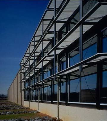
UFC 3-101-01
                                                                                           16 December 2020
                                                                              Change 1, 5 January 2021
   4-2.1            Scope Changes. .................................................................................. 25
   4-2.2            Calculations of Gross Building Area. ................................................... 25
   4-3           PRE-DESIGN SERVICES. ...................................................................... 29
CHAPTER 5 DESIGN AND POST-DESIGN SERVICES .............................................. 31
   5-1           GENERAL. .............................................................................................. 31
   5-2           DESIGN SERVICES. ............................................................................... 31
   5-2.1            Design Charrettes. ............................................................................... 31
   5-2.2            Architectural Compatibility Submittal. .................................................. 31
   5-2.3            Architectural Basis of Design/Design Analysis..................................... 32
   5-2.4            Specifications....................................................................................... 34
   5-2.5            Architectural Drawings. ........................................................................ 35
   5-2.6            Color Boards and Binders. ................................................................... 37
APPENDIX A BEST PRACTICES ................................................................................ 39
   A-1           INTRODUCTION. .................................................................................... 39
   A-2           WHOLE BUILDING DESIGN GUIDE. ..................................................... 39
   A-3           PLANNING ISSUES. ............................................................................... 39
   A-4           LOCAL CONSTRUCTION METHODS, MATERIALS AND SKILLS....... 40
   A-5           BUILDING ENVELOPE. .......................................................................... 40
   A-6           AIR BARRIER MOCK-UP TESTING. ...................................................... 48
   A-7           EXTERIOR INSULATION AND FINISH SYSTEM (EIFS). ...................... 50
   A-8           DAYLIGHTING. ....................................................................................... 50
APPENDIX B GLOSSARY ........................................................................................... 64
   B-1           ACRONYMS ............................................................................................ 64
   B-2           DEFINITION OF TERMS ......................................................................... 68
APPENDIX C REFERENCES ....................................................................................... 70

                                                     FIGURES

Figure 4-1       Sample Gross Building Area Calculation ............................................ 27
Figure 4-2       Sample Block Plan................................................................................. 28
Figure A-1       Effects Of Building Massing on Daylight Availability ......................... 52
Figure A-2       Examples of Passive Daylighting Strategies ...................................... 53
Figure A-3       Building Orientation Can Maximize Daylight Exposure ..................... 54
Figure A-4       Example of Architectural Shading Devices ........................................ 55
Figure A-5       Diagram of Toplighting Strategies ...................................................... 57
                                                           iii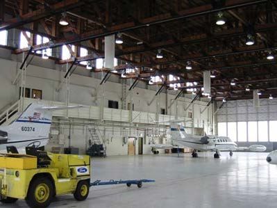
UFC 3-101-01
                                                                                   16 December 2020
                                                                      Change 1, 5 January 2021
Figure A-6 Examples of Toplighting Applications................................................ 58
Figure A-7 Example of Clerestory Application ..................................................... 58
Figure A-8 Examples of Sidelighting Applications............................................... 59
Figure A-9 Examples of Roof Shapes.................................................................... 60
Figure A-10 Example of Splayed Skylights ............................................................. 60
Figure A-11 Example off an Active Daylighting System that Tracks the Sun and
    Directs Daylight into the Building....................................................................... 62
Figure A-12 Example of Solar-Adaptive Shading ................................................... 62

                                                   TABLES

Table 2-1       Interior Acoustic Requirements for Typical Spaces ............................. 7
Table 2-2       Acoustic Requirements for Typical Facilities ....................................... 8
Table 3-1       Building Façade Sound Isolation ......................................................... 23
Table 4-1       Gross Building Area .............................................................................. 26
Table A-1       Construction Mock-Up Guidance Matrix .............................................. 49
Table A-2       Comparison Of Glass Types (From Alpenglass Heat Mirror) ............. 56

                                                        iv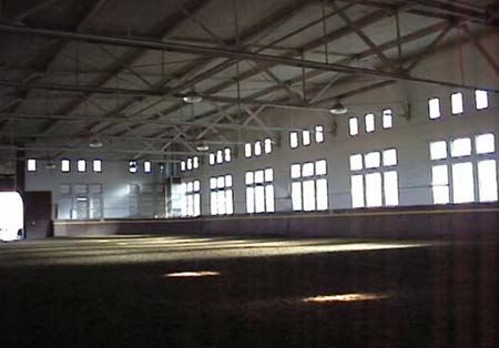
UFC 3-101-01
                                                                       16 December 2020
                                                                 Change 1, 5 January 2021
                              CHAPTER 1 INTRODUCTION

1-1           PURPOSE AND SCOPE.

This UFC provides technical requirements, model code modifications, and requirements
for architectural design services. Architects must use the information in this document
in the development of plans, specifications, calculations, construction contract
documents, and Design-Build Requests for Proposals (RFP). The information in this
UFC serves as the minimum architectural requirements. Project conditions and
programmatic requirements may dictate the need for designs that exceed these
requirements.

1-2           APPLICABILITY.

This UFC applies to all agencies of the U.S. Armed Services and their contractors that
are preparing construction contract documents for Department of Defense-owned
facilities. These criteria are applicable in the 50 states, the District of Columbia, Puerto
Rico, U.S. territories and possessions, and as far as practical, at installations in foreign
countries. This UFC applies to all types of construction regardless of funding, including
properties listed or eligible for listing on the National Register of Historic Places, as well
as National Guard and Reserve projects constructed on military installations or non-
military DoD property. Certain specialized facilities carry more stringent requirements.
See UFC or other criteria that are applicable to the respective specialized facility that is
being designed. This UFC is applicable to the traditional architectural services
customary for Design-Bid-Build design services and for Design-Build construction
contracts.

1-3           GENERAL BUILDING REQUIREMENTS.

Comply with UFC 1-200-01, DoD Building Code. UFC 1-200-01 provides applicability of
model building codes and government unique criteria for design disciplines and building
systems, as well as for accessibility, antiterrorism, security, high performance and
sustainability requirements, and safety. Use this UFC in addition to UFC 1-200-01 and
the UFCs and government criteria referenced therein.

1-3.1         Environmental Severity and Humid Locations.

The architectural design must incorporate systems and details to meet the
environmental corrosivity conditions for the specific project location, as defined by its
Environmental Severity Classification (ESC). See UFC 1-200-01 for determination of
ESC for project locations. The humidity conditions must also be considered during
design; humid locations are those in ASHRAE climate zones 0A, 1A, 2A, 3A, 3C, 4C,
and 5C (as identified in ASHRAE 90.1).

1-4           BACKGROUND.

UFC 1-200-01 implements and supplements 2018 International Building Code (IBC) as
the building code for DoD. Chapter 2 of this UFC further modifies the IBC for
                                              1
UFC 3-101-01
                                                                      16 December 2020
                                                            Change 1, 5 January 2021
architecture-specific design requirements and is organized by the chapter of the IBC
that each section modifies. Apply any section in the 2018 IBC that is not specifically
referenced as it is written in the 2018 IBC.

The 2018 IBC section modifications are one of four actions, according to the following
legend:

[Addition] – Add new section, including new section number, not shown in 2018 IBC.

[Deletion] – Delete referenced 2018 IBC section or noted portion of a section.

[Replacement] – Delete referenced 2018 IBC section or noted portion and replace it
with the narrative shown.

 [Supplement] – Add narrative shown as a supplement to the narrative shown in the
referenced section of 2018 IBC.

1-5          OVERVIEW OF THIS UFC.

Brief descriptions of the various chapters and appendices of this UFC follow.

      •      CHAPTER 2 – MODIFICATIONS TO IBC. Chapter 2 provides
             supplemental requirements for applying the 2018 IBC architectural
             provisions to conventional DoD building design by listing required
             modifications for specific 2018 IBC sections.
      •      CHAPTER 3 – DESIGN. Chapter 3 includes architectural design
             requirements, such as design quality, building orientation, and hazard
             prevention.
      •      CHAPTER 4 – PROGRAMMING AND PLANNING. Chapter 4 includes
             requirements for space planning and building area calculations.
      •      CHAPTER 5 – PRE-DESIGN, DESIGN AND POST-DESIGN SERVICES.
             Chapter 5 includes a detailed description of these services, including
             design charrettes, Architectural Compatibility Submittals, Architectural
             Basis of Design, Specifications, and Drawings.
      •      APPENDIX A – BEST PRACTICES. This chapter contains useful
             recommendations and guidance on a number of important topics ,such as
             planning issues, local construction methods, building envelope
             considerations, air barrier testing, and daylighting data.
      •      APPENDIX B – GLOSSARY. This section includes acronyms and
             definitions of terms.
      •      APPENDIX C – REFERENCES. This section contains a list of references
             used in this document. The publication date of the code or standard is not
             included in this document. Unless otherwise specified, the most recent
             edition of the referenced publication applies.

                                           2
UFC 3-101-01
16 December 2020
Change 1, 5 January 2021
1-6 CYBERSECURITY.
All control systems (including systems separate from an energy management control
system) must be planned, designed, acquired, executed, and maintained in accordance
with UFC 4-010-06, and as required by individual Service Implementation Policy.
1-7 ADDITIONAL REQUIREMENTS.
When performing work for different Activities within the U.S., additional regional or
service-specific requirements apply. Confirm with the Authority Having Jurisdiction
(AHJ) the applicability of any regional requirements.
3UFC 3-101-01
16 December 2020
Change 1, 5 January 2021
This Page Intentionally Left Blank
4UFC 3-101-01
16 December 2020
Change 1, 5 January 2021
CHAPTER 2 MODIFICATIONS TO THE IBC
2-1 CHAPTER 7 – FIRE AND SMOKE PROTECTION FEATURES.
2-1.1 SECTION 721 - PRESCRIPTIVE FIRE RESISTANCE.
721.1 – General [Supplement]
Use the UL Fire Rated Assemblies Directory or Nationally Recognized Testing
Laboratories for design of fire-resistance-rated wall, floor, and roof assemblies in
addition to this section.
2-1.2 SECTION 722 - CALCULATED FIRE RESISTANCE.
722.1 – General [Supplement]
Use the UL Fire Rated Assemblies Directory or Nationally Recognized Testing
Laboratories for design of fire-resistance-rated wall, floor ,and roof assemblies in
addition to this section.
2-2 CHAPTER 8 – INTERIOR FINISHES.
2-2.1 SECTION 802 GENERAL.
802.8 - Paint and Coatings Selection [Addition]
Base paint selection on Master Painters Institute’s (MPI’s) Detailed Performance
Standards for the coating materials and MPI’s Architectural Painting Specification
Manual for the system. Do not use MPI’s “Intended Use” standards. Refer to The
Society for Protective Coatings (SSPC) standards, National Association of Corrosion
Engineers (NACE) standards, and UFC 3-190-06 for painting steel and concrete
structures, particularly in marine and other severe environmental locations.
2-3 CHAPTER 12 – INTERIOR ENVIRONMENT.
2-3.1 SECTION 1202 – VENTILATION.
1202.2.3 - Enclosed Roof Spaces [Addition]
Ventilate enclosed roof spaces created outside the building thermal envelope. For
sloped roofs, ventilation must comply with IBC Section 1202 Ventilation. Ensure that
moisture transfer from ventilated attics into the building is minimized.
2-3.2 SECTION 1206 - SOUND TRANSMISSION.
1206.1 - Scope [Supplement]
Section 1206.4 applies to other occupancies.
5UFC 3-101-01
16 December 2020
Change 1, 5 January 2021
1206.4 - Interior Acoustics for Other Occupancies [Addition]
Design so that interior acoustics coordinate with the architecture, fire protection,
mechanical ,and structural design. A comprehensive acoustical design must include
considerations for sound isolation, building mechanical system noise and vibration
control, room finishes, and space adjacencies.
There are basically two types of sound transmission; airborne and structure-borne.
Structure-borne sound is transmitted through a material by vibrations and re-radiated to
another point (such as upper floor foot traffic). Sound transmission requirements are
performance-based. Refer to the Glossary in this guidance for added explanations and
definitions of acoustical terms such as STC (Sound Transmission Class) and NIC
(Noise Isolation Class). Table 2-1 provides acoustic requirements for common facility
and space types.
1206.4.1 - Interior Acoustics Reference Criteria [Addition]
Spaces such as Special Access Program Facilities (SAPF) and Sensitive
Compartmented Information Facilities (SCIF) must comply with specific criteria to be
accredited for operation. Specialty spaces including television and radio broadcast
facilities, music auditoria, large lecture halls (50 people or more), network operations
centers, or other spaces will require an acoustical consultant as an integral member of
the design team.
The following references include explanations, guidelines, design strategies, and
prediction tools to aid in meeting the above required acoustic criteria.
• UFC 3-450-01 “Noise and Vibration Control”
• UFC 4-010-05 “Sensitive Compartmented Information Facilities Planning,
Design and Construction”
• Sound Matters from General Services Administration
• ANSI/ASA S12.2, Criteria for Evaluating Room Noise
• ASTM E1130, Standard Test Method for Objective Measurement of
Speech Privacy in Open Plan Spaces Using Articulation Index
• ASTM E2638, Standard Test Method for Objective Measurement of the
Speech Privacy Provided by a Closed Room
6UFC 3-101-01
16 December 2020
Change 1, 5 January 2021
Table 2-1 Interior Acoustic Requirements for Typical Spaces
Space Acoustic Requirements
Sound Isolation (1) Background Reverberation
Partitions Doors (2) Noise Level (3) Time
(4) STC 60 or greater STC 50 or greater 25 < 1.0 sec
Auditorium
Unaccompanied
STC 50 STC 25 30 n/a
Housing (UH)
Child Care STC 50 STC 25 35 < 0.8 sec
Clinic/ Health Unit STC 50 STC 25 35 < 1.0 sec
Conference Room STC 50 or greater STC 30 or greater 30 < 0.8 sec
Classroom STC 50 STC 30 35 < 0.6 sec
Firing Range STC 65 or greater STC 55 or greater n/a n/a
Food Service STC 55 STC 25 or greater 40 < 1.4 sec
Hearing Room STC 55 STC 35 30 0.6-0.7 sec
Laboratory: Dry STC 50 STC 25 45 < 1.4 sec
Library STC 50 STC 30 40 < 1.2 sec
Open Office n/a STC n/a (5) < 1.0 sec
40
(6) STC 35-50 STC 25 35 n/a
Private Office
Place of Worship STC 55 STC 35 30 0.8-1.4 sec (7)
1. Sound Isolation requirements are stated in terms of Sound Transmission Class (STC), a laboratory
performance metric. See also Facility-Specific UFC for more detailed requirements, which take
precedence.
2. STC requirements for most doors (STC 30 and below) can be achieved by using door seals on standard
doors. For higher sound isolation requirements, consider using a vestibule, sound rated door(s) or a
combination of the two.
3. Background Noise Level requirements are stated in terms of Noise Criteria (NC) or RC Mark II levels. NC
and RC Mark II levels are considered equivalent for design purposes; however, RC Mark II noise levels
provide additional means to describe the quality of a sound for assessment purposes.
4. Assumes space is primarily used for speech functions. Multipurpose auditoria with music programming
must have criteria established by the Government or project acoustical consultant in the response to a
proposal.
5. Consider a sound masking system if privacy is important in open office areas. A sound masking system
will not alleviate NIC project requirements in other areas of a building. Refer to ASTM E2638 for additional
information regarding privacy design considerations in open office areas
6. Criteria dependent on privacy requirements of the occupants.
7. Criteria to be refined by the Government or project acoustical consultant based on specific worship type.
If a space type is not included in the above Table 2-1, the standards in Table 2-2
include interior acoustic requirements for other space/building types.
7UFC 3-101-01
16 December 2020
Change 1, 5 January 2021
Table 2-2 Acoustic Requirements for Typical Facilities
Reference Standard to Meet Project
Facility/ Space Acoustic Requirements (1, 2)
Type Sound Background Room Mechanical System
Isolation Noise Level Finishes Noise & Vibration
Administrative/ Office
Buildings ASHRAE HVAC
• Open Offices ASHRAE HVAC
GSA PBS-P100 Applications GSA PBS-P100
Applications Handbook,
• Private Offices (see Section Handbook, Ch. 49 (see Section
Ch. 49 – Noise &
• Conference Rooms 3.5.3) – Noise & Vibration 3.5.3)
Vibration Control
• Training Rooms Control
• Lobbies
Child Facilities
ASHRAE HVAC
• Child Care
ANSI S12.60 ANSI S12.60 Parts ANSI S12.60 Applications Handbook,
• Day Care
Parts 1 and 2 1 and 2 Parts 1 and 2 Ch. 49 – Noise &
• Child Development
Vibration Control
• K-12 Schools
Housing
ASHRAE HVAC
• UH ASHRAE HVAC
IBC Applications UFC 3-450-01,
• Multifamily Applications Handbook,
(See Section Handbook, Ch. 49 Noise and
Residences Ch. 49 – Noise &
1206) – Noise & Vibration Vibration Control
• Single Family Control
Vibration Control
Residences
FGI – Sound & FGI – Sound & FGI – Sound &
Medical Care Vibration: Design Vibration: Design Vibration: Design FGI – Sound & Vibration:
• Hospitals Guidelines for Guidelines for Guidelines for Design Guidelines for
• Clinics Health Care Health Care Health Care Health Care Facilities
Facilities Facilities Facilities
Research Facilities NIH – Design NIH – Design
NIH – Design NIH – Design
• Laboratories Requirements Requirements
Requirements Requirements Manual
• Associated Lab Manual Manual
Manual (Section 6.5)
Support Spaces (see Section 6.5)
ASHRAE
ASHRAE HVAC
Applications
IC Tech Spec for Applications Handbook,
SCIF and SAPF Handbook, Ch. 49 UFC 4-010-05
ICD/ICS 705 Ch. 49 – Noise &
– Noise & Vibration
Vibration Control
Control
ASHRAE HVAC
Legal Facilities
U.S. Courts U.S. Courts Design U.S. Courts Applications Handbook,
• Courts
Design Guide Guide Design Guide Ch. 49 – Noise &
• Associated Court
(Chapter 14) (Chapter 14) (Chapter 14) Vibration Control
Support Spaces
1. Chapters and sections referenced are intended to facilitate quick reference of the above standards and
not exclude the requirements in the rest of the document.
2. Requirements in the above referenced standards do not supersede requirements stated in Table 2-1 if
there is a discrepancy.
8UFC 3-101-01
16 December 2020
Change 1, 5 January 2021
2-4 CHAPTER 14 – EXTERIOR WALLS.
2-4.1 SECTION 1401 – GENERAL.
1401.2 - Corrosive Environments [Addition]
For corrosion prone locations as defined in UFC 1-200-01, protect steel surfaces by hot-
dipped galvanizing or providing stainless steel. Use Type 316L stainless steel when
using stainless steel. Protect hot-dipped galvanized metal with an industrial coating in
addition to galvanizing, as galvanized metal will still corrode in these environments.
Isolate dissimilar metals (for example, aluminum and steel, stainless steel and carbon
steel, and zinc-coated steel and uncoated steel) by appropriate means to avoid the
creation of galvanic cells which occur when dissimilar metals come in contact.
2-4.2 SECTION 1404 - INSTALLATION OF WALL COVERINGS.
1404.3.5 - Building Envelope Vapor Retarders [Addition]
For building enclosure systems or environmental conditions not covered elsewhere in
IBC Article 1404, design the enclosure using simplified or transient design tools
referenced in the ASHRAE Handbook of Fundamentals, Chapter 25, Heat, Air and
Moisture Control in Building Assemblies, and the following sections. Do not provide
multiple vapor retarders that trap moisture between the retarders. Select vapor
retarders in accordance with ASTM C755. Based on the results of the analysis
described in this section, design the assemblies for appropriate diffusion control.
1404.3.5.1 Vapor pressure differential calculation.
First determine the vapor pressure difference between indoor and outdoor climates. For
exterior vapor pressure, use the mean outdoor dry bulb and dew-point temperatures for
the coldest and hottest months in UFC 3-400-02. If the vapor pressure difference is
less than 0.25” Hg (847 Pa), place the vapor retarder with appropriate permeance for
the application on the predominantly high vapor pressure side of the assembly.
1404.3.5.2 Vapor pressure differential greater than 0.25 Hg (847 Pa).
If the vapor pressure difference between indoor and outdoor climates is greater than
0.25” Hg (847 Pa), perform a job-specific simplified or transient vapor transmission
(hygrothermal) analysis for walls, roofs, and exposed floors (and floors over
crawlspaces) based on project specific climate as defined by UFC 3-400-02, and the
specified components and materials. Indicate the temperature and relative humidity for
the inside and the outside of the building; a complete listing of building components,
including the vapor retarder; their thickness, location, thermal resistance and
permanence; and building location and use.
1404.3.5.2.1 Simplified Hygrothermal Analysis.
9UFC 3-101-01
16 December 2020
Change 1, 5 January 2021
Use the steady state dewpoint or Glaser methods described in the ASHRAE Handbook
of Fundamentals (Chapter 25), using the mean outdoor dry bulb and dew point
temperatures for the hottest and coldest months.
1404.3.5.2.2 Transient Hygrothermal Analysis.
Use a mathematical model that simulates transient hygrothermal conditions, such as
WUFI/ORNL (ASTM Manual 40 reviews these models). If the WUFI model is selected,
use the climate data included in the WUFI program in lieu of UFC 3-400-02. Users of
such methods must understand their limitations, and interpretation of the analysis
results must be done by a trained person to reasonably extrapolate field performance
approaching the design results. For the mathematical model method, use interior
conditions based on a dewpoint of 53°F (12°C) in summer conditions and a dewpoint of
40°F (5°C) in winter conditions. The maximum threshold must be a surface relative
humidity of 80% averaged over a period of 30 days to achieve a successful building
enclosure assembly for temperatures between 40°F and 120°F (5°C and 50°C) and
other criteria described in Chapter 6 of ASHRAE Standard 160. These are thresholds
above which mold can grow and building assemblies deteriorate.
1404.3.6 - Floor Slab Vapor Retarders. [Addition]
Floor slabs on grade must have a vapor retarder of 0.05 perms or less meeting the
requirements of ASTM E1745 Class A. Under slab vapor retarders must be durable
enough to withstand construction activity and must be terminated around the perimeter
and penetrations detailed according to the manufacturer’s instructions. Additionally,
specifications must require measurement of slab relative humidity in accordance with
ASTM F2170 to meet the requirements of the floor finish manufacturer or must include
an application of a topical moisture mitigation material.
1404.3.7 - Roof Vapor Retarders. [Addition]
Provide moisture analysis of the roof assemblies per paragraph titled, Building Envelope
Vapor Retarders. Roof assemblies on concrete slabs must include a vapor retarder on
top of the concrete and a vented metal deck to control moisture in the concrete from
affecting roof assemblies. However, design low-slope roof assemblies using rigid
insulation without a vapor retarder whenever possible. Install vapor retarder in
accordance with guidance in the NRCA Roofing and Waterproofing Manual.
1404.4.3 - Sill Pan Flashing [Addition]
Penetrations such as windows and louvers in the exterior wall assemblies must have
pan flashing installed in the rough opening sill. This pan sill flashing must have end
dams at both jambs a minimum of 2 in. (50 mm) high and a rear dam of 2 in. (50 mm)
high. Comply with ASTM E2112, the requirements in Chapter 4, Masonry, Brick
Industry of America (BIA) Tech Notes, and the SMACNA Architectural Sheet Metal
Manual recommendations.
1404.13.2 - Selection of Windows and Glazing. [Addition]
10UFC 3-101-01
16 December 2020
Change 1, 5 January 2021
Based on a life cycle cost analysis (LCCA), select windows and glazing with the best
possible performance from a U-factor, Solar Heat Gain Coefficient (SHGC), daylighting,
and Visible Transmittance (VT) for the fenestration. Optimize the emissivity coatings to
control both heat gain into the building due to solar radiation and heat loss from the
building. Select frames with thermal breaks. Include flashings under fenestration in an
appropriate manner. Fenestration must meet both code and UFC 4-010-01
requirements. Do not use steel, wood, or plastic-clad wood windows in locations with
Environmental Severity Classifications (ESC) of C4 or C5. See UFC 1-200-01 for
determination of ESC for a project location.
1404.13.3 - Aluminum Windows. [Addition]
Aluminum windows must be heavy-duty commercial quality systems; conforming to
AAMA/WDMA/CSA 101. For window reinforcing purposes, concealed 316L stainless
steel or aluminum reinforcing inserts are required. All internal fasteners must be 316L
stainless steel. Aluminum windows must have anodized aluminum finish and color to
meet the requirements in the applicable installation exterior architectural guidelines.
1404.13.4 - Operable Windows. [Addition]
Operable windows must open outwards. Provide locks which discourage the opening of
windows during HVAC system operation. Provide window guards at all upper floor
operable windows of housing projects in compliance with ASTM F2090.
1404.13.5 - Window Installation and Details. [Addition]
Install windows according to ASTM E2112. Provide concrete step detail that prevents
water from being driven directly under window sills. Seal all exterior window and door
rough openings to prevent water infiltration into wall cavities including sealing exterior
wall and interior side furred out walls.
1404.13.6 - Window Screens. [Addition]
Window screen must be mounted on the inside of the window frame with aluminum
window frame screens matching the color of the window frame. Provide the anodized
aluminum screen frames with 316L stainless steel spring clips to hold screen frame
securely in window frame. Screen material must be plastic-coated fiberglass or
aluminum mesh.
1404.13.7 - Weatherstripping. [Addition]
Provide nonferrous metal and UV-resistant vinyl weather stripping. Weatherstripping
must be factory applied, and limit infiltration to 0.25 cubic feet/min/square foot (1.698
cubic meter/min/square meter) in accordance with ASTM E283.
1404.13.8 - Storefronts [Addition]
11UFC 3-101-01
16 December 2020
Change 1, 5 January 2021
Exterior storefront systems must be heavy-duty commercial quality aluminum system
with anodized aluminum finish and color to meet the requirements in the applicable
installation exterior architectural guidelines; and conform to AAMA/WDMA/CSA 101.
Storefront doors must be medium stile. Install storefronts according to ASTM E2112.
1404.13.9 - Exterior Glazing [Addition]
Exterior windows must have insulated glazing system (outer lite low E with an air space
and interior lite meeting IBC requirements for wind and windborne debris protection,
where applicable, and UFC requirements for Antiterrorism protection). Consider
building energy efficiency, occupant comfort, daylighting, acoustic performance, and
security when selecting exterior window and glazing systems. Coordinate glazing tint
with applicable installation exterior architectural guidelines unless otherwise noted,
sustainability recommendations and energy requirements. Unless otherwise required,
unshaded glazing must be factory tinted; shaded glazing at storefront requiring see-
through visibility may be clear, non-tinted.
2-4.3 SECTION 1407 - EXTERIOR INSULATION AND FINISH SYSTEMS
(EIFS).
1407.7 - Exterior Insulation and Finish Systems (EIFS) Use and Detailing [Addition]
Selection of EIFS systems must be based on a LCCA that considers maintenance
requirements and frequency of recoating. Use only self-draining EIFS systems. Do not
install EIFS within 6 in (150 mm) of grade, or in areas where it will be subject to abuse
by moving vehicles or equipment, such as a loading dock. Do not use EIFS in areas of
heavy pedestrian traffic, or if such use cannot be avoided, specify high-impact resistant
system. Use high-impact systems a minimum of 4 ft. (1220 mm) above grade where
subject to damage from pedestrian traffic or lawn maintenance equipment.
Construction documents must provide specific design details for windows, trim,
expansion joints, and drainage planes. Comply with the criteria listed in the latest
version of EIFS Standards & ICC-ES Acceptance Criteria document produced by the
EIFS Industry Members Association (EIMA). Where EIFS is applied to a (side) wall
which has an eave from the roof, a premolded polypropylene / use PVC kickout flashing
to channel the water away from the exterior wall.
1407.7.1 EIFS in High Wind Zones.
In areas with design wind loads up to 35 psf (170 Kg/m2) (118 mph or 190km/h),
adhered EIFS must only be permitted provided the EIFS assembly includes a minimum
5/8-in.- (16-mm-) thick glass-fiber-faced siliconized gypsum sheathing fastened with
corrosion-resistant screws that have a minimum 3/8-in- (10-mm-) diameter washer
heads fastened to engineered light-gage metal framing spaced 16 in (405 mm) on
center with screws spaced 4 in (100 mm) on center. In areas with higher wind speeds,
the contractor must provide \1\ wind-tested assemblies and submit test documentation
establishing performance under design /1/ wind-loads in accordance with ASCE/SEI 7.
2-4.4 SECTION 1410 - GYPSUM BOARD CONSTRUCTION.
12UFC 3-101-01
16 December 2020
Change 1, 5 January 2021
1410.1 - Prevention of Mold [Addition]
Use glass mat gypsum (paperless or non-cellulose facing) sheathing for exterior
applications and use glass mat or moisture/mold resistant gypsum wall board for the
interior face of exterior walls (prevents food source for mold). On exterior walls, use only
interior wall finishes that allow water vapor within the wall to escape into the conditioned
space. Do not use vinyl wall coverings, oil-based paint, and other vapor-resistant
materials as interior finishes for exterior walls.
2-5 CHAPTER 18 – SOILS AND FOUNDATIONS.
2-5.1 SECTION 1805 - DAMPPROOFING AND WATERPROOFING.
1805.2.2 - Walls [Supplement]
If required to address hydrostatic pressure or as recommended by the geotechnical
report, provide drainage planes combined with waterproofing material and a footing
drain on below-grade walls.
1805.4.2 - Foundation Drain [Supplement]
Footing drains and under-slab drainage must be incorporated based on the
recommendations of the geotechnical engineering report.
2-5.2 SECTION 1808 – FOUNDATIONS.
1808.6.5 - Insulation [Addition]
Where the energy model or code requires insulation for slab-on-ground floors, use high-
density (40-100 psi [276-689 kPA] depending on floor loading with a safety factor of 5)
extruded polystyrene under the vapor retarder. Apply requirements of ASCE 32-01 to
keep soils thawed to minimize frost action in cold regions. Coordinate final assembly U-
Factors with the mechanical engineer to comply with overall facility energy
requirements. Protect all insulation from weather, including rain, ultraviolet solar
radiation, mechanical abuse, compression, or accidental or deliberate movement from
its location during its service life.
2-6 CHAPTER 20 - ALUMINUM.
2-6.1 SECTION 2002 - MATERIALS.
2002.2 - Corrosion Prone Locations. [Addition]
For corrosion prone locations as defined in UFC 1-200-01, protect aluminum surfaces
with an industrial coating or heavy-duty anodized coating. Isolate dissimilar metals (for
example, aluminum and steel, stainless steel and carbon steel, and zinc-coated steel
13UFC 3-101-01
16 December 2020
Change 1, 5 January 2021
and uncoated steel) by appropriate means to avoid the creation of galvanic cells which
occur when dissimilar metals come in contact.
2-7 CHAPTER 21 - MASONRY.
2-7.1 SECTION 2115 - MASONRY DETAILING AND MISCELLANEOUS
PROVISIONS. [Addition].
2115.1 - Masonry Details [Addition]
Comply with the Brick Industry Association (BIA) Technote 7, Technote 18A, and
Technote 21 for specific brick masonry recommendations and other topic specific
Technotes as applicable.
2115.2 - Expansion Joint Position and Location [Addition]
No single recommendation for positioning and spacing of vertical expansion joints can
be applicable to all structures. Analyze each building to determine the potential
horizontal and vertical movements and make provisions to relieve excessive stress that
might be expected to result from such movement. Place expansion and crack control
joints in accordance with BIA Technote 18A. Place expansion joints symmetrically on
building elevations. Indicate expansion joints on the contract drawings.
2115.3 - Plastic and Membrane Through-Wall Flashing [Addition]
Plastic flashings and asphalt-impregnated felt flashings are prohibited.
2115.4 - Clearance Between Masonry and Back-up Construction [Addition]
Provide a 2-in. (50 mm) minimum clear dimension from the face of cavity insulation or
sheathing material to the back of the exterior wythe of masonry. See American
Concrete Institute, ACI 530 for additional information. See BIA Technote 21 for
additional guidance.
2115.5 - Flashing at Penetrations and Projections [Addition]
Do not design structural steel frame members to be exposed inside a cavity wall.
Provide flashing at all penetrations exposed into the cavity such as columns or beams,
and at floor slabs, wall projections and recesses, and wall bases. All projections,
recesses, and caps must be flashed and sloped away from the wall to ease drainage.
2115.6 - Location of Weep Holes [Addition]
Provide open-head joint weeps at all through-wall flashing for brick masonry. Locate
weeps on the same course as the flashing. Space weep holes at 24 in. (610 mm) on
center for brick masonry and 32 in. (815 mm) on center for concrete masonry. Locate
weeps above the level of the finished grade, including landscape mulching, to prevent
the weeps from becoming clogged with foreign material. Weeps must be designed to
be open-head joints with corrugated plastic inserts only. Provide masonry vents at top
14UFC 3-101-01
16 December 2020
Change 1, 5 January 2021
of walls and below continuous shelf angles. These provide better ventilation of cavity
spaces to prevent buildup of warm, moist air at the tops of cavities. For single-wythe
exterior CMU walls, provide a flashing/weep system for open CMU cells to drain to the
exterior.
2-8 CHAPTER 22 - STEEL.
2-8.1 SECTION 2203 - PROTECTION OF STEEL FOR STRUCTURAL
PURPOSES.
2203.2 - Corrosive Environments [Addition]
For corrosion prone locations as defined in UFC 1-200-01, protect steel surfaces by hot-
dipped galvanizing or providing stainless steel. Use Type 316L stainless steel when
using stainless steel. Protect hot-dipped galvanized metal with an industrial coating in
addition to galvanizing, as galvanized metal will still corrode in these environments.
Isolate dissimilar metals (for example, aluminum and steel, stainless steel and carbon
steel, and zinc-coated steel and uncoated steel) by appropriate means to avoid the
creation of galvanic cells which occur when dissimilar metals come in contact.
2-8.2 SECTION 2211 COLD-FORMED STEEL LIGHT-FRAME
CONSTRUCTION.
2211.3 - Above-Grade Finished Floor Elevation [Addition]
Provide a minimum of 18 inches (455 mm) clear space above finished grade for light
frame metal floor construction.
2-9 CHAPTER 23 - WOOD.
2-9.1 SECTION 2304 – GENERAL CONSTRUCTION REQUIREMENTS.
2304.12.1.1 - Joists, girders, and subfloor [Replacement]
Provide a minimum of 18 inches (455 mm) clear space above finish grade and
crawlspaces for light-frame wood construction. Wood girders that are closer than 12
inches (305 mm) to the exposed ground in crawlspaces or unexcavated areas located
within the perimeter of the building foundation must be naturally durable or preservative-
treated wood.
2-10 CHAPTER 25 – GYPSUM BOARD, GYPSUM PANEL PRODUCTS AND
PLASTER.
2-10.1 SECTION 2515 - TRIM AND MOLDINGS [Addition].
2515.1 - Materials.
In high humidity interior areas (for example, bathrooms, locker rooms, pools, trainers),
areas open to the exterior (for example, mechanical rooms, and hangars), and spaces
15UFC 3-101-01
16 December 2020
Change 1, 5 January 2021
that are not conditioned by design or may not be conditioned during prolonged periods
due to deployment, use PVC or plastic trims, casings, and accessories in lieu of metal,
which may rust over time.
16UFC 3-101-01
16 December 2020
Change 1, 5 January 2021
CHAPTER 3 DESIGN
3-1 DESIGN QUALITY.
The following principles are adapted from GSA’s Guiding Principles for Federal
Architecture:
• Provide facilities in an architectural style and form that is distinguished,
and which will reflect the dignity, enterprise, vigor, and stability of the
Federal Government. Place emphasis on the choice of designs that
embody the finest contemporary American architectural thought relative to
the building’s function. Pay specific attention to the possibilities of
incorporating into such designs qualities that reflect the regional
architectural traditions of that part of the country in which buildings are
located. Designs must adhere to sound construction practice and utilize
materials, methods, and equipment of proven dependability. Buildings
must be economical to build, operate and maintain; resilient, sustainable,
and accessible.
• The development of an official style must be avoided. Design must flow
from the architectural profession to the Services and not vice versa.
• Consider the choice and development of the building site as the first step
of the design process. Pay special attention to the general ensemble of
streets and public places of which these buildings will form a part. Where
appropriate, locate buildings to permit a generous development of
landscape.
3-1.2 Installation Exterior Architecture.
Most military installations and service design agencies have published design
guidelines that contain criteria relative to achieving, maintaining, and emphasizing a
positive exterior visual environment. Follow the design guidance contained in these
documents. In the absence of such guidelines, design facilities to harmonize with the
character of existing facilities considered historically or architecturally significant to the
area. Air Force projects must comply with the Air Force Corporate Facilities Standards
and applicable Installation Facilities Standards.
3-1.3 Historic Architecture.
Follow the Secretary of Interior’s Standards for Rehabilitation and Guidelines for
Rehabilitating Historic Buildings for repair or renovation of historic facilities and new
construction near historic facilities.
3-1.4 Projects in the National Capital Region (NCR).
In accordance with the National Capital Planning Act of 1952, as amended, submit all
master plans and designs for proposed construction projects in the NCR to the National
17UFC 3-101-01
16 December 2020
Change 1, 5 January 2021
Capital Planning Commission (NCPC) for appropriate reviews and approvals consistent
with the timelines issued by the NCPC.
3-2 BUILDING ORIENTATION.
Establish building siting in \1\ in accordance with the Regulating Plan of the Installation
Master Plan, see UFC 2-100-01, section 2-9.1.2./1/ Optimize building layout and
orientation with regard to functional arrangement, access, exterior appearance, views,
present and expected future site acoustic conditions, and other considerations.
Utilize the site environmental factors to orient buildings to minimize annual facility
energy use and to optimize daylighting. Consider seasonal solar angles and prevailing
winds to enhance energy performance of the building within the site-specific micro
climate. See Appendix A Best Practices, paragraph Daylighting for additional
information. See also UFC 1-200-02.
3-3 HAZARD PREVENTION.
Design facilities to comply with 29 CFR Occupational Safety and Health Act (OSHA).
Pay particular attention to lead and asbestos particulates, which may be lying on top of
materials to be removed, and polychlorinated biphenyls (PCBs) that are part of caulking
and sealant materials that may have been absorbed into adjacent building materials and
require grinding.\1\
Design fixed ladders and roof hatches in accordance with 29 CFR 1910.23 and the IBC,
according to the most stringent requirements. Design handrails, guardrails, and fall
arrest systems to comply with 29 CFR 1910.28, 29 CFR 1910.140, and the IBC,
according to the most stringent requirements. /1/
3-3.1 Radon.
Evaluate and mitigate radon per the appropriate Service and Installation regulations.
3-3.1.1 Identification of Radon.
3-3.1.1.1 Army, Air Force and Navy.
Check the Environmental Protection Agency’s (EPA's) Map of Radon Zones (by state),
EPA 402-R-93-071, to determine the radon area.
3-3.1.1.2 Navy.
For Navy requirements follow OPNAV M-5090.1C Chapter 30 “Radon Assessment and
Mitigation”, and the Navy Radon Assessment and Mitigation Program (NAVRAMP)
Guidebook for Naval Shore Installations. NAVRAMP provides for compliance with the
procedural requirements of the Toxic Substances Control Act (TSCA) related to radon.
For existing buildings check the results of the NAVRAMP survey by contacting the
NAVFAC Facility Engineering Systems Command (FEC) Air Pollution Engineer.
18UFC 3-101-01
16 December 2020
Change 1, 5 January 2021
3-3.1.1.3 Air Force.
Check the results of the AF Radon Assessment and Mitigation Program (RAMP) study
of 1987. During that study, all Air Force Installations were screened for radon in
existing structures. Installations were classified as being of low, medium, or high risk.
Incorporate radon reduction measures in the construction of new facilities at those
installations designated as medium or high risk if installation not included in EPA Priority
Areas No. 1. See AFMAN 48-148 for additional guidance on radon sampling and
mitigation.
3-3.1.1.4 Lack of Radon Data.
If no data is available for the area or site to make a prediction of radon levels, then a
radon survey must be done, or a passive radon mitigation system installed.
3-3.1.2 Radon Mitigation System Design.
Provide passive under-slab depressurization systems for projects located in Priority
Areas No. 1 (predicted average radon level is greater than 4/pCi/L). Change the system
to active, if needed, based on follow-up testing. Check the following EPA documents
available from the EPA’s Publications about Radon website,
https://www.epa.gov/radon/publications-about-radon
• EPA's Model Standards and Techniques for Control of Radon in New
Residences, U.S. Environmental Protection Agency, Air and Radiation
(6604-J), EPA 402-R-94-009,
• Radon Prevention in the Design and Construction of Schools and Other
Large Buildings, EPA/625/R-92-016,
3-3.2 Paints with Lead, Cadmium, and Chromium.
Painted surfaces containing lead, cadmium, and chromium, as well as operations
involving these and other heavy metals are regulated by the Occupational Safety and
Health Act (OSHA) and the Resource Conservation and Recovery Act (RCRA). Paints
containing lead, cadmium, and chromium are often found as protective coatings on
structural steel, tanks, piping, metal building components, exterior coatings on metal
surfaces, aircraft, and ships. Paints containing lead, cadmium, chromium, and other
heavy metals are used in current operational processes in various facilities, such as
aircraft maintenance hangars, and ship maintenance and repair facilities. If not properly
controlled and managed, dust and particulates containing lead, cadmium, chromium,
and other heavy metals can be generated from operational activities resulting in
contaminated dust deposits on building surfaces that must be remediated during
renovation, alteration, repair, or demolition activities. For Navy and Marine Corps
projects involving renovation, alteration, repair, or demolition, comply with UFC 3-810-
01N.
19UFC 3-101-01
16 December 2020
Change 1, 5 January 2021
Facilities with heavy metal paints or coatings, or facilities that operated or will operate
utilizing heavy metals or chemicals in their operations, must comply with the
Occupational Safety and Health Act 29 CFR 1910.141 General Environmental Controls,
29 CFR 1910.1025 Lead, 29 CFR 1910.1026 Chromium (VI), and 29 CFR 1910.1027
Cadmium. The requirements found in the CFR may affect facility design requirements,
which include but are not limited to: separate toilets and washing/bathing areas, change
rooms, decontamination areas, clothes washing facilities, areas for controlled disposal
of contaminated waste and work clothes, high-efficiency particulate air (HEPA) systems
and filters, and deluge showers. Designate areas of facilities utilizing these heavy
metals or chemicals as regulated areas whenever exposure can be expected to be in
excess of the permissible exposure limit(s), and demarcate from the rest of the
workplace in a manner that adequately establishes and alerts building occupants of the
boundaries of the regulated area. Design facilities to allow the performance of the
OSHA and EPA air sampling and monitoring as required for the specific hazardous
metal or chemical in use.
3-3.3 Beryllium Coatings and Compounds.
Beryllium is an essential material used in the aerospace, electronics, energy,
telecommunications, information technology, defense, medical, and nuclear industries.
Beryllium is classified as a strategic and critical material by the U.S. Department of
Defense. Beryllium is used industrially in three forms: as a pure metal, as beryllium
oxide, and most commonly as an alloy with copper, aluminum, magnesium, or nickel.
Workers in industries where beryllium is present may be exposed to beryllium by
inhaling or contacting beryllium in the air or on surfaces. Beryllium is a highly toxic metal
and workers who inhale beryllium are at an increased risk of developing chronic
beryllium disease (CBD) or lung cancer. Coatings and compounds containing beryllium
are used in current operational processes in various facilities, such as aircraft
maintenance hangars, and ship maintenance and repair facilities. If not properly
controlled and managed, dust and particulates containing beryllium can be generated
from operational activities resulting in contaminated dust deposits on building surfaces
which must be remediated during renovation, alteration, repair, or demolition activities.
For Navy and Marine Corps projects involving renovation, alteration, repair, or
demolition, comply with UFC 3-810-01N.
Facilities that operated or will operate utilizing beryllium in their operations must comply
with the Occupational Safety and Health Act 29 CFR 1910.1024 Beryllium, 29 CFR
1915.1024 Beryllium, and 29 CFR 1926.1124 Beryllium. The requirements found in the
CFR may affect facility design requirements, which include but are not limited to:
separate toilets and washing/bathing areas, change rooms, decontamination areas,
clothes washing facilities, areas for controlled disposal of contaminated waste and work
clothes, high-efficiency particulate air (HEPA) systems and filters, and deluge showers.
Designate areas of facilities utilizing these heavy metals or chemicals as regulated
areas whenever exposure can be expected to be in excess of the permissible exposure
limit(s), and demarcate from the rest of the workplace in a manner that adequately
establishes and alerts building occupants of the boundaries of the regulated area.
20You can also read